Kenwood NEXEDGE NXR-710 Instruction Manual
Vhf digital base-repeater/ uhf digital base-repeater
Hide thumbs
Also See for NEXEDGE NXR-710:
- Service manual (118 pages) ,
- Instruction manual (17 pages) ,
- Instruction manual (17 pages)
Advertisement
Quick Links
Advertisement

Related Manuals for Kenwood NEXEDGE NXR-710


Summary of Contents for Kenwood NEXEDGE NXR-710
- Page 1 NXR-710/ NXR-810 VHF DIGITAL BASE-REPEATER/ UHF DIGITAL BASE-REPEATER INSTRUCTION MANUAL BASE-RELAIS NUMÉRIQUE VHF/BASE-RELAIS NUMÉRIQUE UHF MODE D'EMPLOI BASE-REPETIDOR DIGITAL VHF / BASE-REPETIDOR DIGITAL UHF MANUAL DE INSTRUCCTIONES © B62-2199-00 (K) 09 08 07 06 05 04 03 02 01 00...
-
Page 2: Unpacking And Checking Equipment
However, there is no guarantee that the interference will not occur in a particular installation. If this equipment does cause harmful MICROPHONE interference to radio or television reception, which can be determined by turning the equipment off and on, the user is encouraged to try to Connect an optional KMC-30, KMC-35, KMC-27A, KMC-27B, correct the interference by one or more of the following measures: or KMC-9C Kenwood microphone to the MIC jack on the front • Reorient or relocate the receiving antenna. panel. • Increase the separation between the equipment and receiver. • Connect the equipment to an outlet on a circuit different from that to which the receiver is connected. -
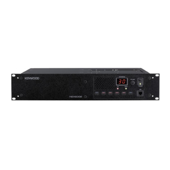
Page 3: Controls And Functions
CONTROLS AND FUNCTIONS ■ Front Panel CH/STATUS VOLUME POWER BUSY q Speaker y MIC jack Connect a microphone to this 8-pin modular jack. w CH/STATUS Display Two 7-segment digits display the channel number, name, u Programmable Function keys or status. Press these keys to activate their programmable functions. e VOLUME control Rotate to adjust the audio. i BUSY indicator Lights green while a signal is being received. r POWER switch o TX indicator t POWER indicator Lights red while transmitting. - Page 5 TERMINAL MIC(Modular Jack) Pin Name Pin Number Description Specification notes Power Output 13.6V PTT Signal/ Input Impeadance 22kΩ TXD2 Asynchronous Send MICG MIC GND MIC GND MIC Input 600Ω Hook Detection/ HOOK RXD2 Asynchronous Receive Input Impeadance 100kΩ Data TEST/SPEAKER CONNECTOR Pin Name Pin Number Description...
-
Page 6: Mandatory Safety Instructions To Installers And Users
MANDATORY SAFETY INSTRUCTIONS TO INSTALLERS AND USERS • Use only manufacturer or dealer supplied antenna. • Antenna Minimum Safe Distance: 120 cm (4 feet), 50% duty Cycle. • Antenna Gain: 0 dBd referenced to a dipole. The Federal Communications Commission has adopted a safety standard for human exposure to RF (Radio Frequency) energy which is below the OSHA (Occupational Safety and Health Act) limits.