Table of Contents
Advertisement
C
X
D
C
X
C
X
D
C
X
D
S
e
S
e
C
o
p
y
r
i
g
h
t
(
C
)
C
a
n
o
n
I
n
c
.
C
o
p
y
r
i
g
h
t
(
C
)
C
a
n
o
n
I
n
c
.
I
-
1
S
D
I
-
1
S
I
-
5
0
G
I
-
5
0
G
r
v
i
c
e
M
r
v
i
c
e
M
C
a
n
o
n
I
n
c
.
J
a
p
a
n
C
a
n
o
n
I
n
c
.
J
a
p
a
n
M
e
d
i
c
a
l
T
e
c
h
n
i
c
a
l
S
e
r
v
i
c
M
e
d
i
c
a
l
T
e
c
h
n
i
c
a
l
S
e
r
v
i
c
P
P
r
r
i
i
n
n
t
t
e
e
M
a
r
M
a
r
y
s
t
e
m
y
s
t
e
m
/
5
0
/
5
0
a
n
u
a
l
a
n
u
a
l
e
D
e
p
t
.
A
l
l
r
i
g
h
t
s
R
e
s
e
r
v
e
d
e
D
e
p
t
.
A
l
l
r
i
g
h
t
s
R
e
s
e
r
v
e
d
d
b
b
y
y
C
C
a
a
n
n
o
o
n
n
I
I
n
n
c
c
.
.
.
2
0
0
7
R
e
v
.
0
5
a
.
2
0
0
7
R
e
v
.
0
5
a
C
C
.
d
.
Advertisement
Chapters
Table of Contents

Related Manuals for Canon CXDI-50C


Summary of Contents for Canon CXDI-50C
-
Page 2: General
Distribution Control No. Issued on Service Manual Introduction This service manual belongs to a series of after-service guides Canon Inc. publishes as part of its comprehensive product quality guarantee program. This service manual consists of seven chapters; General Information, Installation Guide, Feature Information, Repair Guide, Parts Catalog, Troubleshooting and Service Manual Report. - Page 3 In order to ensure safety, the best performance, setup, repair and maintenance work can only be performed by the technicians received the service training specified by Canon Inc. If there are order required certificates or restrictions specified by the law or ordinances, those regulations of the country must be observed.
- Page 4 1.Zerlegung, Zusammenbau, Einstellung und Wartung Zerlegung, Zusammenbau, Einstellung und Wartung dürfen nur von einem Wartungstechniker durchgeführt werden, der an einem von Canon vorgeschriebenen Wartungslehrgang teilgenommen hat. 2.Entfernen von Abdeckungen Schalten Sie unbedingt die Stromversorgung des Instruments aus, bevor Sie die Abdeckungen zwecks Wartung und Reparatur entfernen.
- Page 5 According to the “IEC60601-1-1:2000”, devices installed in the patient environment are restricted to “electric medical devices conforming to IEC60601-1”. The Control PC, operation unit, and the magnetic card reader, etc. options that are parts of the CXDI-C3S are classified under the data processing device standard (IEC60950), therefore these items should not be installed in the patient environment.
- Page 7 Content General ..............................1 CXDI-1 System Block Diagram ......................2 System Diagram...........................3 CXDI Image Processing........................4 Specifications ............................5...
- Page 8 3M 250001 CXDI-50C Fluorescent substance of CXDI-50G has been changed to CsI from GOS in CXDI-50C so that the CXDI-50C can be ranked as the more superior performance model (high sensitivity model) than CXDI-50G. The read-out method of image data is read-out from both sides of LANMIT which is same as CXDI-50G.
- Page 9 1. General Remo. Power Box Imaging Unit (CXDI-50G/50C) AC120V/230V AC Power IN OUT PUT 1 Control/Signal Control/Signal X-Ray OUT PUT 2 Operation Control/Signal RS232C SERIAL(COM1) Unit Control PC (CXDI-C3S) ID Unit RS232C SERIAL(COM2) LAN1 (Option) X-Ray Generator Mouse MOUSE LAN2 Key Board KEY BOARD SCSI...
- Page 10 1. General 2.1 Standalone System CXDI-50G/50C 2.2 Total System Total System Block Diagram (Example) Patient Circumstances or Medical Room CXDI-50G/50C POWER BOX 50 Power Supply Grid Imaging Unit Unit 1st/2nd AC230V Insulation with reinforcement Protective Grounding Remote switch AC230V Basic Insulation CXDI-40G/ X-ray generator CXDI-40E...
- Page 11 1. General 3.1 Proccess Flow Born image Offset correction Correction Gain correction processing Raw image Defect correction dtstore Original image Characteristic extraction QA processing • Sharpening QA image • DEP • Gradation processing DICOM output • MTF enhancement Diag. image (Frequency enhancement) •...
-
Page 12: Specifications
1. General The CXDI-50G/50C (Imaging Unit/Power Box) is the Digital Cassette that has the mobility and can be used on the optional angles. (1) Imaging Unit This unit consists of the internal sensor, 50Di Board, 50AD Board, 50LED Board and its outer cover. - Page 13 1. General Item Remarks When the internal temperature of Imaging Unit is above 49 degree Celsius, its state is changed to sleep Imaging restriction mode. And the Imaging (Imaging Prohibition) prohibition will be continued when the internal temperature is below 48 degree Celsius.
- Page 14 1. General (2)Power Box This unit consists of 40XRAY Board, 50Power Supply and its outer cover. The function; the signal transition between Imaging unit and Control PC, the interface to the X-ray generator equipment and power supply to the Imaging unit has been implemented. Item Content Remarks...
-
Page 17: Table Of Contents
Content Caution during the installation ....................1 Product Configuration ......................2 Packing Diagram ........................5 Installation Procedures ......................7 Lists of Tool Needed for Installation ................7 System Installation Procedures ..................8 Installation ........................... 10 Connection to each unit....................10 Starting up and shutting down the System.............. - Page 18 2. Installation Manual Please pay attention to the followings when installing the system. (1) If the equipment is hoisted, lowered or transport, it must be supported at both sides by a minimum of two people so there is no danger of it falling. (2) If a forklift, etc.
-
Page 19: Product Configuration
2. Installation Manual 2.1 Product Configuration List Item Name Remarks CXDI-50G/50C Imaging Unit With Sensor cable (3/7m) Power Box 100 - 120/230V X-ray I/F cable Remote switch Cable clump For fixing the sensor cable Screw (M4 x 6 mm) XB1-1400-603 For fixing the cable clump Sensor Information File (FD) Power supply cable (with AC plug) - Page 20 2. Installation Manual 2.2 Configuration Name Name Power Box CXDI-50G/50CImaging Unit Remarks 3/7m Remarks I/F and Power supply (3/7m) Name X-ray I/F cable Name Remote switch Connection with X-ray Power Box power source Remarks Remarks generator ON/OFF Name Cable clump Name Screw (M4 x 6mm) Remarks...
- Page 21 2. Installation Manual Name Sensor Information file FD Name Power supply cable For Power Box Remarks Remarks (100/120/230V each type) - 4 -...
-
Page 22: Packing Diagram
2. Installation Manual 3.1 X-ray Digital Camera System (CXDI-50G/50C) (1) CXDI-50G/50C assemble package (2) CXDI-50G/50C Imaging Unit package - 5 -... - Page 23 2. Installation Manual (3) Power Box assemble package (4) Grid (optional) - 6 -...
-
Page 24: Installation Procedures
2. Installation Manual 4.1 Lists of Tool Needed for Installation Tool needed for new installation. Tool Name Unit Remarks General Tools 1 set PC/AT compatible Note PC (OS: Microsoft Windows XP Professional recommend) LAN Card For Note PC (as required) Mouse PS/2 type Keyboard... -
Page 25: System Installation Procedures
2. Installation Manual 4.2 System Installation Procedures Step Conditions and Checkpoints Reference Section Unpacking and checking the -There must be no missing parts, damage, product’s constituent parts dents, etc. -There must no color changes in the shock sensor. Connect the Imaging Unit -Handle the instrument carefully, as it may and the Power Box be damaged if something is hit against it,... - Page 26 2. Installation Manual Operation Manual Explain the operation to the user Final parameter adjustment -The engineer in charge must be consulted Operation Manual prior narrowing down the adjustments to the final values. Inserting the backup floppy -It must be confirmed at re-start that backup “(15) Backing up Setting Data to FD”...
-
Page 27: Connection To Each Unit
2. Installation Manual 5.1 Connection to each unit 5.1.1 Connection diagram Control PC CXDI-50G CXDI-50G/50C Remote switch POWER SUPPLY PCBXRAY POWER BOX - 10 -... - Page 28 2. Installation Manual 5.1.2 Connecting to the Power Box Removing the cover Remove the 5 screws from the back of the power box and the 2 screws on each side at the bottom of the power box. Also remove screws on the far side Check the jumper pin settings on the PWB-40XRAY board in the power box.
- Page 29 2. Installation Manual Cable connections 1) Loosen the lock nut for each cable and connect the cables to the power box. Then fix the cables by tightening the lock nuts. Sensor cable X-ray I/F cable Lock nut Remote cable Note: To avoid the risk of damage when the cables are removed with very large force, Check tightening torque of the bush (refer the following figure).
- Page 30 2. Installation Manual 3) Connecting each cable connector. Connected to Sensor cable X-ray I/F cable Connected to Remote cable Connected to 4) After completing the connections, attach the power box cover. 5) Connect the LAN cable to the back of the power box. LAN cable - 13 -...
- Page 31 2. Installation Manual 6) Connect the power cable to the back of the power box. Power cable Power switch Power cable X-ray I/F cable Remote cable CXDI-50G/50C sensor cable LAN cable - 14 -...
- Page 32 2. Installation Manual 5.1.3 Connection diagram for Control PC rear panel Operation unit RS-232C cable Mouse Keyboard LAN cable (straight cable) (Between Control PC and network) Operation unit VGA cable (Connector 1) LAN cable (Between Control PC and Power Box) Power cable - 15 -...
-
Page 33: Starting Up And Shutting Down The System
2. Installation Manual 5.2 Starting up and shutting down the System Perform the following sequences when starting up and shutting down the system. 5.2.1 Sequence for Starting up the System Perform the following sequence when turning the system power on. If you do not perform the correct sequence, the imaging unit cannot be recognized, resulting in an error. -
Page 34: X-Ray Controller Interface
2. Installation Manual 5.3 X-ray Controller Interface 5.3.1 Interface Signal Description CXDI X-ray Generator X-ray emission signal SW level ON) RX_REQ X-ray emission signal (2nd SW level ON) Detect X-ray emission signal ON Start X-ray emission Imaging possible? Generator Setup timer RX_COM Enable X-ray emission End X-ray emission... - Page 35 2. Installation Manual • When normal imaging • When timeout due to RX_REQ not negating - 18 -...
- Page 36 2. Installation Manual 5.3.2 Signal names and functions in the connection with the X-ray generator <X-ray Sync Signal> Signal name Functions X-ray exposure signal Indicates that an X-ray exposure is ordered at the X-ray generator side. This signal needs to be retained at least for T period.
- Page 37 2. Installation Manual The connection with CXDI-50G/50C and X-ray generator equipment Connection conditions 1. The X-ray exposure signal line must be insulated, and its total impedance must be 100 ohms or less. 2. The maximum contact voltage of the X-ray exposure authorization signal line is AC 250V and DC 30V, and its current ranges from 10mA to 2A.
- Page 38 2. Installation Manual 5.3.3 Rating and Characteristics for Relay and Photo coupler (on PWB-40XRAY Board) (1) RL1 (Power Relay/Plug-in terminal type) 1) Rating (Operational coil) Rated Coil Coil Inductance Pick-up Dropout Maximu Power Rated curre resistance (mH) voltage voltage m voltage consumption voltage Armature...
- Page 39 2. Installation Manual (2) PCI (Photo-coupler) 1) Maximum Ratings (Ta = 25°C) CHARACTERISTIC SYMBOL RATING Forward Current (RMS) 50 mA Forward Current /°C -0.7(Ta≥53°C) ∆ Pulse forward current Reverse Voltage Collector-Emitter Voltage 80 V Emitter-Collector Voltage Collector Current 50 mA Collector Power Dissipation 150 mW (1 Circuit)
-
Page 40: Network Settings 1
2. Installation Manual 5.4 Network Settings 1 1. Objective The CXDI-50G/50C imaging part communicates with the control PC by using Ethernet [IEEE802.3u (100Base-TX)] to transfer X-ray images. The control PC performs DICOM transfer in order to use Ethernet to transfer the obtained images to the printer and storage device. - Page 41 2. Installation Manual 3.2 Network setting for Screwcap.ini The CXDI software communicates with the imaging part through screwcap.dll by using the communication protocol for sending and receiving commands and responses. In conjunction with the communication, Screwcap.ini retains the information of the connected CXDI-50G/50C and control PC such as network addresses.
- Page 42 2. Installation Manual 3.3 Network setting stored in the CXDI-50G/50C sensor The factory default setting is shown in the table below. This setting is not necessary unless you have changed the setting. Item to be set Factory default value Sensor IP address 192.168.100.11 Subnet mask 255.255.255.0...
-
Page 43: Setting The Fixed Roi Areas
2. Installation Manual Setting the Fixed ROI Areas Purpose Set the fixed ROI area on the sensor to expose by the fixed ROI area because user can not get the proper image by the Auto ROI area. Setting method 2-1) Investigate the actual size and position of the ROI that is required. 2-2) Designate the SIZE, POSITION, and NUMBER (max 5)* on the sensor. - Page 44 2. Installation Manual 2-5) The “DENSITY ADJUSTMENT CONTROL” screen appears. Confirm that the sensor is set with a sensor switch button. Press the [Fixed ROI Area] key. 2-6) Press the [Area setting] key. Area setting button 2-7) The fixed ROI 1 setting screen appears. Input values A to D from step 3) into the edit box, and press [ENABLE].
- Page 45 2. Installation Manual 2-8) The display returns to the “DENSITY ADJUSTMENT CONTROL” screen. Confirm that POSITION and SIZE fields not set in step 5) to step 7) are disabled (dimmed). If they are not dimmed, press the [Area setting] key, and press [DISABLE] in fixed ROI * settings.
-
Page 46: Adjusting The Photo Timer
2. Installation Manual 5.6 Adjusting the photo timer <Outline> The photo timer installed in the imaging unit is adjusted so that the exposure time of the X-rays generated by the X-ray generators is to OFF using the optimal value. * This work necessitates performing some adjustments inside the X-ray generators. In order to ensure that the work will proceed smoothly, discuss the schedule and other details with the representative of the manufacturer of the X-ray generators. - Page 47 Imaging Unit Rex value CXDI-40EG, CXDI-50G CXDI-40EC, CXDI-50C (2) Adjust the radiation dosage gradually using the option buttons (such as the H.S button, L.S button, “+” (plus) and “-“ (minus) button) on the X-ray generator, and decide on the final dosage.
-
Page 48: Settings
2. Installation Manual 5.7 Settings (1) Checking and Setting the Date and Time Description about CCR application in ‘Setting’ may change to some degree depending on the versions of application. For CCR application, see “New Function Descriptions” issued for every version if necessary. Purpose The date and time is set to Japan standard time at factory shipment. - Page 49 2. Installation Manual (2) Checking the Firmware Version Purpose 1-1) Failing to use the proper versions of the firmware and PLD code with the CXDI application can result in an error, and system operation cannot be guaranteed. Therefore, the versions of the firmware must be checked to ensure that they are correct.
- Page 50 (4) Connect Telnet by referring to “Telnet Connection” in the Tool Software Operation Manual for Ethernet. (5) Check the versions of the firmware and PLD code on the screen displayed after the login. login: canon Password: ******** Firmware version CXDI-50G firmware Ver.1.01.00...
- Page 51 2. Installation Manual (3) Installing Firmware and PLD Code Purpose Write exposure code and PLD code into the Flash ROM of the PWB-50Di in the imaging unit. Notes Be sure to check that the CXDI is connected to the system. Procedure 3-1) Installing the firmware Write the firmware by referring to “Firm Write Tool Software (Firmwrite.exe)”...
- Page 52 2. Installation Manual (4) Checking the Sensor Serial No. Purpose If the sensor serial number and the sensor serial number stored in the flash ROM of the PWB-50Di differ from the image data file name stored in the hard drive of the Control PC due to replacing the PWB-50Di or imaging unit, the connected sensor can not be detected after the CXDI application is launched.
- Page 53 2. Installation Manual (5) Set Up Startup Menu Purposes 1-1) Register the CXDI application software to the “Startup Group”. The CXDI application software is scheduled to start automatically at the CXDI system starting 1-2) Change the window view size Hide the other application screen view except the CXDI application software. 1-3) Delete the CXDI application software from the “Startup Group”.
- Page 54 2. Installation Manual Change the window view size 4-1) After the CXDI application software start, press [Alt] + [Tab] key to show the “Debug mode” prompt screen. 4-2) After the command prompt screen appears, click the icon (called System icon) where is in right-top of its window.
- Page 55 2. Installation Manual 5-6) “Taskbar and Start Menu Properties” appears. Click “Start Menu” tab, and then click Taskbar and Start Menu Properties⇒Start Menu⇒Classic Start⇒Menu Customize 5-7) The “Remove Shortcuts/Folders” dialog box appears after click the “Remove” button. And double-click the “Startup folder” 5-8) Remove the “ccrstart.bat”...
- Page 56 2. Installation Manual (6) Identifying the Sensor Units Purpose In order for the control PC to identify the sensor units connected, the sensor serial number of each sensor unit is input to the Control PC. Notes 2-1) These operations must always be implemented at the installation stage and when any of the Imaging Units (sensor) or Control PC (hard disk) has been replaced or when the combination of equipment has been changed.
- Page 57 2. Installation Manual 2) Procedure 2-1) Start up the CXDI system. 2-2) After the exposure screen appears on the operation unit, use the keyboard to enter Debug mode. (Use [Alt] + [Tab].) 2-3) “Welcome to CCR” screen appears. Select the command “1. Set-Up…” 2-4) The “Setting Mode (0: Normal, 1: Expert) [0=0×0]:”...
- Page 58 2. Installation Manual (8) Table Setup Settings Purpose Adjust the CXDI operation unit's TABLE SETUP to match the exposure conditions (X- ray tube voltage, X-ray tube current, msec or mAs value) of the X-ray generator. Procedure 2-1) Start the CXDI system. 2-2) Open the TABLE SETUP Change window from the Normal Exposure window.
- Page 59 2. Installation Manual (9) Performing the Annotation Settings Purpose The settings for imprinting the annotation onto the film and the settings of the characters used for the annotation are performed. Procedure 2-1) Once the normal radiographic screen has started, open the annotation setting screen. SYSTEM →...
- Page 60 2. Installation Manual (10) Network Connections Network settings Purpose These settings are for connecting the CXDI to the network. 1-1) Set the CXDI’s IP address, subnet mask and default gateway in Windows XP. 1-2) Set the printer and storage output destinations and parameters on the user screen. Checkpoints 2-1) This item involves checking the details of the checks performed on network setting parameters among the pre-installation inspection details and setting these parameters.
- Page 61 2. Installation Manual 3-7) Upon completion of the setting, restart the Windows XP. 3-8) Check the communication test in the sequence below to verify whether the CXDI is now part of the network. To check the connections at the TCP/IP level, use the “ping” command from the command prompt.
- Page 62 2. Installation Manual Set the printer and storage device which serves as the external output destinations. In this case, one printer and one storage device are set. 4-1) Printer settings A. Open the output destination setting screen from the user menu. System SETUP MENU DESTINATION...
- Page 63 2. Installation Manual Input parameters [Fig 3] - 46 -...
- Page 64 2. Installation Manual 4-2) Storage settings A) Open the output destination setting dialog from the user menu. System SETUP MENU DESTINATION STORAGE * Up to four storage units (2 of which can be used for output at the same time) can be set. B) Press the “Storage1”...
- Page 65 2. Installation Manual D. After setting the output destinations, follow the procedure below to check whether images can actually be transmitted. Return to the user menu, capture a sample image (one X-ray image), and transmit the image to the printer and storage.
- Page 66 2. Installation Manual Parameter List (Separate Document 1) DICOM storage device In the CXDI, DICOM data transfer is performed using the transfer software module “send_image” .The settings for these parameters are described below. Parameter Meaning Description -m maxPDU * The CXDI automatically * The DICOM standards do not allow Maximum PDU value in uses 131072 internally for...
- Page 67 2. Installation Manual Parameter Meaning Description * This parameter is used * This parameter does not affect DICOM This parameter dumps the simply as “-v”. data transfer. transfer log. * DUL and SRV are dumped. * This parameter is used to make the transfer software put the debugging character string on the console.
- Page 68 2. Installation Manual Parameter List (Separate Document 2) DICOM printer In the CXDI, DICOM printers are administered separately according to printer product. The transfer software module is “print_stuff”. The settings for these parameters are described below. Parameter Meaning Description -C copies * This parameter is used in the * This parameter is set according to the This parameter uses a...
- Page 69 2. Installation Manual -L sessionLabel * This parameter is used in the The parameter is not transferred over Film session label DICOM Basic Film Session DICOM if it is not designated. (character string) (2000, 0050). * This parameter may be displayed in * The label for the film session some form or another depending on the is for designation purposes...
- Page 70 2. Installation Manual * The designation method varies according to the printer. For example, the MLP190 uses -m NORMAL. * This parameter is used in the DICOM Basic Film Box (2010, 0150). * This parameter sets the -S configuration If this parameter is not designated, it is printer (image quality) Adjustment information not transferred over DICOM.
- Page 71 2. Installation Manual -B border_density * This parameter is used in the If this parameter is not designated, Border density (Dx100) DICOM Basic Film Box (2010, it is not transferred over DICOM. In (BLACK/WHITE/D x 0100). this case, the printer default values are 100) * This parameter determines the used.
- Page 72 2. Installation Manual -u maxPDU * The CXDI automatically * The DICOM standards do not allow Maximum PDU value in uses 131072 internally for values of 1301073 or higher to be set. byte units operation. * This parameter is used when the * The above value can be operator of the connected storage device overwritten by designating a...
- Page 73 2. Installation Manual * Both the -p and -v parameters should be used. These settings override the - s parameter. -V filename * The parameter is used for * This parameter does not affect DICOM This parameter dumps the analysis after the transfer data transfer.
- Page 74 2. Installation Manual Examples of parameters used with different makers and types of printers (reference) Name Default Parameters Significance • Trimming OFF Kodak MLP190 -A 320 -T NO -M CUBIC –m • Cubic spline interpolation NORMAL -S CS000 • Smoothing: normal (entered in param member) •...
- Page 75 2. Installation Manual • The Kodak service engineer is responsible for setting the smoothing type on-site since it can be changed with each printer. • The rest is done by the printer itself. • Trimming OFF Kodak Imation DryView -A 320 -T NO -M CUBIC –S •...
- Page 76 2. Installation Manual factors have been adjusted. The specifications are as follows although they cannot be set at the present time: 14" x 14" : W=4444, H=4444 (for portraits) 11" x 14" : W=4444, H=3660 (for portraits) • Trimming OFF Fuji CR-DPL/LPD/FM- -A 300 -T NO -M CUBIC -m •...
- Page 77 2. Installation Manual Printer Model Specifications (Reference) Maximum equivalent Name Specifications area in CXDI 2048 x 2560 (@160 µm) Kodak MLP190 80µm x 4096 x 5120 79 µm x 4090 x 5120 (value after passing through the 2018 x 2528(@160 µm) Kodak KELP2180 + print spooler)
- Page 78 2. Installation Manual • Inserting annotations in the image can lead to problems at the hospital. In the QCW, use annotations that are outside of the image. • The designated film size is 11 x 14 inch film, and automatic selection of the magazine and printing has been confirmed.
- Page 79 2. Installation Manual DMAX = 3.2D equivalent curve required by CXDI. Gamma type #17 (SAR system) Density Shift Contrast Point 1 1.57 0.10 1.00 Point 2 2.29 0.15 1.00 - 62 -...
- Page 80 The log output in this case is shown below. ----------------------------------------------------------------------------------- Silent mode; do not print results of all print commands Use verbose mode for DUL and SRV facilities Canon Hidden Special Mode node The host name that is running a print server port...
- Page 81 2. Installation Manual The printer status Return value: 0x28 has returned a CXDI description: DICOM printer status warning warning. (CCRTRANS_WRN_PRN_STATUS) The transfer process was successful, but a warning was returned as the printer status. The log output in this case is shown below. ------------------------------------------------------------------------------------ (Not determined) ------------------------------------------------------------------------------------...
- Page 82 2. Installation Manual Precautions for connecting the server (reference) Equipment Restrictions on connections Transmitting the 0019 shadow group causes a failure, and the group is not received Kodak properly with the default. Its reception is enabled by setting the strictValidation Miil parameter to Off in Miil.
- Page 83 2. Installation Manual As a result of Return value: 0x18 providing the CXDI interpretation: DICOM response warning server with a (CCRTRANS_WRN_RESP) command request, The transmission processing was successful but a warning was returned from the a warning was server. returned as See below for the log output at this time: response.
- Page 84 2. Installation Manual Concerning the Dry View 8700 (reference) LUT (Lookup Table) • Image adjustment parameters that can be changed by users Density : This can be set up to the maximum density of 3.1D. Contrast : This can be set from 1 to 15. •...
- Page 85 2. Installation Manual Dry View 8700 Plus Up to 2 units can be connected. Dry View 8700 Plus + 8800 Multi Input Manager Up to 8 units can be connected. Dry View 8700 Dual + 8800 Multi Input Manager Up to 2 printers can be connected (only with Dry View 8700 Dual) Up to 7 units can be connected.
- Page 86 2. Installation Manual (11) Linearity Check of Transfer Image Density Purpose An SMPTE image is used to check whether the density linearity of the image printed out by the printer and the image displayed on the high-definition monitor matches the density linearity of the image transferred by the CXDI.
- Page 87 2. Installation Manual 3-4) Press the exposure switch on the X-ray generator, and after the exposure, press the END STUDY button. Transfer the SMPTE pattern image to the printer or the high- definition monitor. [Fig. 2] [Fig. 2] 3-5) Measure the densities of the 11 locations (0% to 100%) of test image grayscale on the film or on the monitor.
- Page 88 2. Installation Manual 3-6) Create the graph below based on the data measured in step 5). 3.50 Max setting density 3.00 2.50 2.00 1.50 1.00 0.50 Film base 0.00 density Step As shown in the above graph, the measurement values need only to nearly form a straight line from the minimum density to the maximum density.
- Page 89 2. Installation Manual Fine adjustment 4-1) As the step (3)-3) above, make the system “READY” by selecting the exposure mode “SMPTE” on the exposure screen. [Fig. 4] [Fig. 4] 4-2) On the X-ray generator press the exposure button. After the exposure, adjust the trim so that the gray scale may be located in the center of the image.
- Page 90 2. Installation Manual 4-3) Select the END STUDY and transfer the SMPTE pattern image to the printer or the high-definition monitor. [Fig. 6] [Fig. 6] 4-4) On a printed film or on the monitor, measure the density of 32 steps of the grayscale on the test image.
- Page 91 2. Installation Manual 4-5) As the step (3)-6), create a graph based on the data measured in step 4), and make sure that the data from the minimum density to the maximum density nearly form a straight line. Characteristics of the printer may prevent the data from forming a straight line near the minimum and maximum densities.
- Page 92 2. Installation Manual <Reference 1> In the data and graph below, the data was obtained by setting the Kodak MLP 190 to curve shape 0 (density linear), a maximum density of 3.20, the SMPTE test image was printed out, and the image data was measured. As shown in the graph, the data from the minimum density (film base density) to the maximum density nearly form a straight line.
- Page 93 2. Installation Manual <Reference 2> Example when the graph does not form a straight line In the data and graph below, the data was obtained by using the Kodak MLP 190 to print out the SMPTE test image, and the image data was measured. (1): Shows normal data.
- Page 94 2. Installation Manual (12) Operation Unit Gamma Correction Purpose This procedure is performed so that the image that is printed out or displayed on a high- definition monitor conforms exactly to the exposure image on the operation unit. Notes 2-1) The procedure in “Linearity Check of Transfer Image Density” must be completed. 2-2) If image adjustment for the printer or high-definition monitor has not been made, use the “Gamma Correction Calculation Tool”...
- Page 95 2. Installation Manual Comparison of operation unit image and print image or monitor image. 4-1) Start up the CXDI system. 4-2) Use the two adjustment knobs at the rear of the operation unit to adjust the brightness and contrast of the touch panel screen for optimum visibility. 4-3) On the exposure screen, select the exposure mode “SMPTE”...
- Page 96 2. Installation Manual Operation Unit Image Gamma Correction 5-1) On the QA screen displayed on Step (4) 5) above, select the “Option” tab and the “Gamma Adjustment” button is appeared, and then press this button. [Fig. 3] [Fig. 3] 5-2) The “Gamma Adjustment’ window appears. Change the value for the PREVIEW IMAGE, and press OK.
- Page 97 2. Installation Manual (13) Changing the Total Image Count Purpose When the imaging unit is replaced (including the replacement of the LANMIT) for servicing, the total image count displayed on the user screen can be returned to “0”if necessary. Notes 2-1) The CXDI is connected by the system.
- Page 98 2. Installation Manual 3-4) Changing the items below contained in the file allows you to change the settings for the counter in the user screen. ExpResult.ini file Screen Display Note [SystemCounter] TotalStudy= TOTAL STUDIES Can be overwritten at the UsrStudyCounter= STUDY COUNTER user screen UsrExposure...
- Page 99 5-2) The CXDI application starts. Press the [Alt] + [Tab] keys to switch the program to the Command Prompt screen. 5-3) The message “Welcome to Canon CXDI” appears. Input [8] and press the [Enter] key. (Select “8 Exit”.) 5-4) The Windows XP desktop screen appears.
- Page 100 2. Installation Manual (15) Backing up Setting Data to FD Purpose “Important setting data (setting information which differs for each customer.)” is backed up to floppy disks and hard disks in consideration of possible setting data loss, hard disk corruption or other data errors. In the event that setting data is lost or the hard disk is corrupted, this “Important setting data”...
- Page 101 2. Installation Manual (16) Tool Modes (/np mode) Purpose The tool modes (startup options) are intended in order to check operation, and are used to launch the CXDI application on the control PC by itself, and to display items that are not normally displayed.
- Page 102 2. Installation Manual 4-6) When Setting Mode (0: Normal, 1: Expert) [0=0x0]: appears, select “0: Normal.” 4-7) When CCR SETUP MENU appears, select “7 Scan Sensor Setup”. 4-8) When Capture Device Configuration Table appears, enter the number of sensor to which make the “Max Capture Device”...
- Page 103 2. Installation Manual 4-10)When CCR SETUP MENU appears, press the [Esc] key to return to Welcome to CCR. 4-11) Select the command “8 - Exit” in the “Welcome to CCR” menu to exit the CXDI application. 4-12) After exit the CXDI application and Windows XP desktop appears, starts the command prompt screen (Start ⇒...
-
Page 104: Adjusting The Alignment
2. Installation Manual 5.8 Adjusting the Alignment 1. Outline Align the center of the sensor unit with the center of the X-ray tube. Be sure that the crossing angle is perpendicular. * Alignment of the sensor should be performed based on the assumption that the X-ray generator is set in the correct horizontal and vertical position. - Page 105 2. Installation Manual ● Using a measure or rope, align the vertical position of the sensor unit to the center of the tube so that the distance from the tube to the top and bottom side of the sensor is symmetric. [Side View] (3) Turn on the irradiation ramp of the X-ray generator, cross line of the X-ray tube is cast over the sensor unit.
- Page 106 2. Installation Manual 2) Look in the X-ray tube to check the cross line reflected from the mirror matches the cross line on the X-ray tube. If it does not match, move it right and left or put the spacer before and behind the stand base to align the slight differences.
- Page 107 2. Installation Manual 3.2 Table (1) Fix the mirror (first-face mirror) at the center of the sensor unit. Fix the Mirror (2) Place the level on the sensor unit. Align the table and the sensor horizontally by the adjuster of the table or the spacer.
- Page 108 2. Installation Manual (4) Turn on the irradiation ramp of the X-ray generator, cross line of the X-ray tube is cast over the sensor unit. Align the position to meet the requirements described in 1) and 2) below. 1) Align the position so that the cross lines of X-ray tube and the sensor unit exactly match. If the position is mismatched as shown in [NG] below, the sensor unit and the stand are not aligned horizontally to the X-ray tube.
- Page 109 2. Installation Manual 2) Look in the X-ray tube to check the cross line reflected from the mirror matches the cross line on the X-ray tube. If it does not match, adjust the height of the table by the adjuster or the spacer to align the slight differences.
-
Page 110: Image Quality
2. Installation Manual 5.9 Image Quality (1) Purpose This procedure is used to check the final image quality of the CXDI. Resolution check Tools used (1) Phantom (2) High-resolution monitor or DICOM printer Procedure Procedure/Item Operation/Conditions [Positioning] 1. Adjust the distance between the focal point of the X- ray tube and the CXDI sensor unit. - Page 111 2. Installation Manual Procedure/Item Operation/Conditions 4. Irradiate X-ray and capture the image of a phantom. Exposure 5. Output the image to a high-resolution monitor or Out the image DICOM printer. 6. Set the high-resolution monitor and DICOM printer by High-resolution DICOM printer referring to their instruction manuals.
-
Page 112: Post-Installation Checks
2. Installation Manual 5.10 Post-installation checks Check sheet Checkpoint Checkpoint details Check Align the unit with the X-ray tube Checking the imaging unit Check that the unit does not interfere with the cables. Set the date. Checking the date and time Set the time. - Page 113 2. Installation Manual Checkpoint Checkpoint details Check Inserting the backup floppy Create the backup files in floppy drive by disk and checking the backup re-starting. files (Cannot be used in automobile) Backing up ccr folder D:ccr Check that the CXDI application starts. Registering in startup.
-
Page 114: Dimension
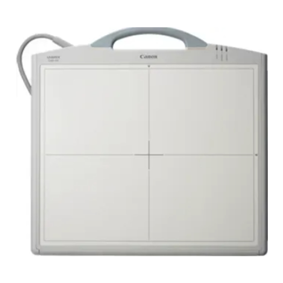
2. Installation Manual (1) Imaging Unit Unit: mm Mass: (50G) 4.8 Kg (except the cable) 5.7 Kg (with 7m cable) 5.2 Kg (with 3m cable) (50C) 4.9 Kg (except the cable) 5.8 Kg (with 7m cable) 5.3 Kg (with 3m cable) - 97 -... - Page 115 2. Installation Manual (2) Power Box Unit: mm Mass: 4.2Kg - 98 -...
- Page 116 2. Installation Manual (3) Remote Switch Unit: mm Mass: 0.5Kg (4) Grid (Optional) Unit: mm Mass: 0.9Kg (Frame) - 99 -...
- Page 119 Content Imaging Unit.......................... 1 Block Diagram (Imaging Unit) ..................1 LANMIT UNIT ......................2 PCB 50AD / PWB/50Di Block diagram................ 4 Imaging Unit ........................5 Power Box ..........................7 PWB-40 X-ray board ..................... 7 Remote switch........................ 7 50 Power supply......................8 Available Imaging Time (Normal Imaging/Long-term Imaging) .........
-
Page 120: Imaging Unit
3. Function Block Diagram (Imaging Unit) 1.1.1 CXDI-50G Power Box 1.1.2 CXDI-50C Power Box... -
Page 121: Lanmit Unit
3. Function LANMIT UNIT 1.2.1 CXDI-50G Reads from One side toward LANMIT. PWB-50Di A/D Conversion PCB-50AD AMP IC Signal Read-out Circuit (PCB-50A) LANMIT... - Page 122 3. Function 1.2.2 CXDI-50C LANMIT is single Sensor Panel unit works as two dummy panel units. The inside of () are expressed the quantity. PWB-50Di A/D Conversion PCB-50AD(1) 1 PWB-50Di AMP IC Signal Read-out Circuit (PCB-50A) LANMIT (1) LANMIT (2)
-
Page 124: Imaging Unit
3. Function Imaging Unit The Imaging Unit’s function is listed below: (1) Converts the acquired X-ray image to light signal using the fluorescent screen and stores. (2) After reading the stored electric signal (Image) from the sensor, perform the A/D conversion and stores it on the frame memory temporally. -
Page 125: Power Box
3. Function 1.4.4 PWB-50Di board The PWB-50Di board has the following functions: (1) The sensor driving control. Reading the digital image signals outputted from the AD converter (PCB-50AD) (2) The communication, the X-ray image transferring with the Control PC through the Power Box on the Ethernet. -
Page 126: X-Ray Board
3. Function PWB-40XRAY The Power Box consists of the following parts; PWB-40XRAY board (X-ray I/F), Power supply, Remote power switch. And it has the function that is the signal transition with Imaging Unit, Power supplying, the signal transition with the X-ray generator. The Power Box can be connected only one Imaging Unit. -
Page 127: Power Supply
3. Function 50 Power supply (1) ACDC power supply Imaging Unit mainly use Rated power supply (input) : AC 100 to 120V/AC 200 to 240V Rated power supply (output) : CH1 9.5V, CH2 9.5V, CH3 6.8V, CH4 -11.5V, CH5 27V (2) Added function a) Over current protection: At detecting the over current, shutdown and reset is performed automatically... - Page 128 3. Function [Overview] There are two available imaging times as follow: 1) Normal imaging (0 - 1000 msec) 2) Long-term imaging (1001 - 3000 msec) From Version 6.0, the maximum imaging time is now 3 seconds for the CXDI-50G sensor, which can be set on the GUI.
- Page 129 3. Function 2. Imaging condition check at the time of upgrade If any of the kV, mA, mAs, cm (except msec) values recorded in the imaging condition table or in each body part information exceeds the limit of the sensor, when the CXDI starts up, a warning message will be displayed (Fig.
- Page 130 3. Function 4. Imaging conditions table It is possible to add values up to 3000 msec and 4800 mAs to the system settings - imaging conditions table on the settings screen. However, if 1001 - 3000msec, 1601 - 4800mAs values are added, a warning message will be displayed only once, saying the values cannot be used with the CXDI-11 - CXDI-31 sensors.
- Page 131 3. Function 5. msec maximum value checking Even if the values recorded in the msec values of calibration/imaging body part within the BodyPart.ini exceed the maximum msec value of the sensor, the OPU can perform the exposure using those values without checking. (This function was already implemented before CXDI v5.1.) It is the same when using the msec imaging conditions table, if a value bigger than the sensor’s maximum msec value is written in the BodyPart.ini file, the value will not be...
- Page 132 3. Function Initialization Switch The LAN can be started with the factory settings when you turn on the power (the main power of the power box and remote switch) by holding down the initialization switch (see figure ) of the power box. The 50G/50C firmware contains the initialization and normal codes.
- Page 133 3. Function This is the procedure for shutting down the CXDI system and accessing to Windows. 1.1 Preparation Prepare a keyboard and mouse. 1.2 Notes (1) Never perform the following operation when the CXDI host program is operating, such as during QA process, image transfer, communication with RIS or generator, etc.
- Page 135 Content Notes............................1 For removing the base cover..................1 About tabs exposed on the internal sensor unit.............. 2 Disassemble/Reassemble....................... 4 Removing Grip unit ....................... 4 Removing the side cover....................5 Removing the cover ....................... 6 Exchanging the sensor cable ..................7 Exchanging the PCB-50 LED ..................
-
Page 136: Notes
4. Repair Guide For removing the base cover The internal sensor unit is fixed with the top cover with base cover screws. Therefore, it gets free when the base cover is removed. Always keep the unit flat after removing the base cover. If the 50G Sensor Unit is set up or tilt, the internal sensor unit drops or shifts down. -
Page 137: About Tabs Exposed On The Internal Sensor Unit
4. Repair Guide About tabs exposed on the internal sensor unit Never touch the tabs when disassembling or reassembling the unit. The tabs toward the grip are exposed on the internal sensor unit when the base cover is removed. Touching tabs may cause to damage them and hinder to scan an image appropriately. - Page 138 4. Repair Guide Do not touch the tabs when replacing the sensor cable. Tabs in Enlarged View Sensor Cable...
-
Page 139: Removing Grip Unit
Former and new parts are not interchangeable. Replace three parts from Key No.1 to 3 in sets to allow the compatibility with a sensor. Body No. 150827 - CXDI-50G Body No. 250001 - Body No. 100056 - CXDI-50C Body No. 200001 -... -
Page 140: Removing The Side Cover
4. Repair Guide Removing the side cover Side cover (R) Sleeve cover Side cover (L) Screw (x2x2) Side cover (C) Shock sensor Shock sensor (pigment) (Color former) Plate Screw (x2)* 1. Loosen the screw (x2x2) fix the side cover (L) and (R). And remove the cover carefully because the cover is pushed into the ditch so as not to come out. -
Page 141: Removing The Cover
This is required only for Japanese market. Both of old and new plates are interchangeable for the other countries. *Application CXDI-50G Body No. 150079 - CXDI-50C Body No. 100009 - Body No. 250001 - Body No. 200001 -... -
Page 142: Exchanging The Sensor Cable
4. Repair Guide Exchanging the sensor cable (1) Removing the Cable Screw M3x8 (x2) Cable clamp 1 Screw M2.6x6 (x2) Screw M2.6x6 (x2) Sensor cable Cable clamp 2 Bush Bend the power line. Cable holder Disconnect the power cable connector. Be careful not to get the cable caught between covers. - Page 143 4. Repair Guide 2. Place the bush into the case on the cover while adjusting the position of the bush so signal cables of 50G/50C sensor cable unit become straight.
- Page 144 4. Repair Guide (2) Cable attachment Special attachment jigs will be used when securing the cable with the cable clamp plate so the cover of the cable will not be caught in cable clamp plate. NOTES: This operation requires below special attachment jigs when installing the cables. Attachment jigs: BY9-6551-000 (in sets with jig A and jig B).
- Page 145 4. Repair Guide Procedures (1) Adjusting position of rubber bush Align the screw holes on the cable clamp assembly and the top cover screw holes. Then, decide the position of attaching the rubber bush. Rubber bush (2) Bending the cable After position of rubber bush is decided, lift the cable and bend it so that the shape of the section will become an oval.
- Page 146 4. Repair Guide (3) Placing the cable Place the cable on the top cover again. (4) Attaching jig A Attach jig A to the cable as shown below. Technical Information The purpose of using jig A is to prevent the cable from spreading and being caught at the part where jig A is bent.
- Page 147 4. Repair Guide (5) Attaching cable clamp plate Place the cable clamp plate on the cable, and lightly tighten the sensor side screw first, and then the outer side screw. Make sure that the cable clamp plate is horizontal. Sensor side screw Outer side screw Sensor side screw (6) Tightening cable clamp plate screws 1...
- Page 148 4. Repair Guide (7) Tightening cable clamp plate screw 2 With the cable clamp inclined as shown above, gradually tighten the screw until there is no space between the cable clamp plate and the cover, and that the space between the outer side cable clamp plate and the cover is about 2.5 mm.
- Page 149 4. Repair Guide (9) Removing jig B While pressing jig B, tighten the outer side screw until the cable is held with the cable clamp plate. Then, loosen the screw slightly to remove jig B. (10) Fully tightening the screws Fully tighten the outer side screw until the cable clamp plate touches against the cover.
- Page 150 4. Repair Guide (11) Checking the screws Check that the screws are fully tightened so there is no space between the edges of the cable clamp plate and the cover on both the sensor side and the outer side. Must be no space Cable may be slightly caught at parts where cable clamp plate is bent...
- Page 151 4. Repair Guide (12) Removing jig A Remove jig A from the cable. (13) Tightening clamp assembly screw Finally, tighten the screws of cable clamp assembly. (14) Checks Check that the cable is not caught in cable clamp plate. NG: Cover of cable is OK: Cover of cable is slightly caught and clamp is not caught but the clamp is...
-
Page 152: Exchanging The Pcb-50 Led
4. Repair Guide Exchanging the PCB-50 LED (1) Removing Screw x2 Washer PCB-50 LED Screw x4 Grid detect sensor Connector Spring Washer Plane Washer Alminium Spacer 1. After removing the connector connected with the PCB-50LED unit, loosen the screw (x2) fixes the Grid detect sensor on the top cover and remove this screw. - Page 153 4. Repair Guide (2) Attaching Attachment of CXDI-50G/50C Grounding Strengthening Parts. 1. Requirements (1) Grounding strengthening parts • PCB-50LED (BG7-2767-100) • Aluminum spacer (BA4-2434-000) • Plain washer M2.6mm (XD1-2100-267) • Spring washer M2.6mm (XD1-3100-267) If procedures in Service Manual Report CXDI-50G 05-013 has already been conducted, the above plain and spring washers should already be attached.
- Page 154 4. Repair Guide 4. Attachment of parts (1) Attach aluminum spacer to the chassis of the sensor unit and then mount PCB-50LED. Tighten the screw (XB1-2260-606) slightly weaker than usual. Otherwise, the screw hole on the chassis of the CXDI-50G will be damaged. It is recommended to use the torque screwdriver for tightening the screw.
- Page 155 4. Repair Guide (2)After attaching the PCB-50LED, use a tester to measure the resistance value between the sensor unit cover and the PCB-50LED through-hole. (Resistance value: 0.1 ohm or less) [How to measure resistance value] 1) Touch the two probes together and check the indicated value. (Example: 0.2 ohm) 2) Measure the resistance value between the bottom of the screw hole (A in the illustration) and through-hole on the PCB-50LED (B in the illustration).
-
Page 156: Removing The Pwb-50Di
4. Repair Guide Removing the PWB-50Di Screw x 9 Connect point (Below) Connect point (Upper) Hold 1. Remove the flat cable. 2. Loosen the screw (M2.6 x 9) fixes the PWB-50Di and remove it. Note: 1. At assembling, insert the connector carefully in the direction of the flat cable. 2. -
Page 157: Removing The Pcb-50Ad
4. Repair Guide Removing the PCB-50AD Contact position Screw x 16 At attaching the flat cable, perform the work with very carefully. 1. Remove the flat cable. 2. Loosen the screw (M2.6 x 16) fixes the PCB-50AD and remove it. Note: 1. -
Page 158: Removing The Pwb-40Xray
4. Repair Guide Removing the PWB-40XRAY 1. Remove the connector of each cable. (1) Sensor cable (J002/CN2) (2) X-ray I/F cable (J004) (3) Remote switch cable (CN4) (4) PWB-40XRAY board/50 Power supply (J001/CN3) 2. Loosen the screw fixes the PWB-40XRAY and remove it. Note: The power supply cable must be removed before assembling. - Page 159 4. Repair Guide (1) Sensor Unit 1) PWB-50Di (BG7-2999) <SW1> Function Not used. Starts the Initialize code by force ON: Yes OFF: No SW1-2 ON Ether Setting FlashROM Read ON: Yes OFF: No Not used. Not used. Not used. Detects cable length automatically ON: Disable OFF: Enable SW1-7 ON ON:3m OFF:7m <SW2>...
- Page 160 4. Repair Guide <SW4> Function LANC I/O address EEPROM N: Disable OFF: Enable Not used. H-UHI N: Use OFF: No use 2) PCB-50LED (BG7-2767) No special setting. 3) PCB-50AD (BG7-9061) No special setting. (2) Power Box 1) PWB-40XRAY (BG7-3069) <JP1> Short the JP1 according to the power unit.
- Page 161 4. Repair Guide Perform the following operations when the unit is replaced. Sensor unit (1) When sensor unit is replaced 1) Set the IP address. (This operation is not required if the default IP address is used.) Refer to “Imaging unit IP address setting” in the Tool Software Operation Manual for Ethernet.
- Page 162 4. Repair Guide 4) Install the sensor serial number. Refer to “(4) Checking the Sensor Serial Number” in “5.2.5 Settings” in “2.5 Installation” of “2. Installation Manual”. 5) Install the sensor data file. Refer to “DP File Write Tool Software” in the Tool Software Operation Manual for Ethernet. To perform this operation, “Sensor Data File FD”...
- Page 165 CXDI-SYSTEM Rev.04 CONTENTS CXDI-50G/50C·········································································································· 1 IMAGING UNIT ······································································································· 2 POWER BOX ············································································································ 3 REMOTE SWITCH UNIT ························································································ 4 IMAGING UNIT (Electrical) ···················································································· 5 POWER BOX (Electrical) ························································································· 6 INDEX OF PARTS NUMBERS ··············································································· 7...
-
Page 166: Cxdi-50G/50C
5....CABLE UNIT, POWER, 100V ......BH4-6494-020 ..... 1 6....CABLE UNIT, POWER, 120V ......BH4-2385-100 ..... 1 7....CABLE UNIT, POWER, 230V ......BH4-6217-030 ..... 1 8....CLAMP, CABLE..........WT2-5859-020..... 1 9....SCREW.............. XB1-1400-603 ..... 1 Key No.1 Key No.2 Key No.3 Key No.4 © Canon Inc. - Page 167 CXDI-SYSTEM Rev.04 Key No.5 Key No.6 Key No.7 Key No.8 Key No.9 © Canon Inc.
-
Page 168: Imaging Unit
SHEET, Q BA4-1783-000 SCREW XB1-2301-206 SCREW Y67-2692-030 CABLE UNIT, 7M Y67-2693-030 CABLE UNIT, 3M Application of the base cover unit with Shimomaru address Body No. 150079- Body No. 100009- CXDI-50G CXDI-50C Body No. 250001- Body No. 200001- © Canon Inc. - Page 169 CXDI-SYSTEM Rev.04 IMAGING UNIT (CXDI-50G/50C) KEY NO. PARTS NO. Q’TY DESCRIPTION MEMO XB1-2300-806 SCREW XB1-2300-806 SCREW BA4-1775-030 SLEEVE, ISOLATION BA4-1776-020 CAP, SLEEVE BA4-1789-000 SENSOR, SHOCK XB1-2260-606 SCREW BA4-1779-000 PLATE, CONDUCTIVE © Canon Inc.
- Page 170 Gold plated XB1-2260-606 SCREW XB1-2260-606 SCREW XB1-2260-606 SCREW BH6-5730-000 SWITCH UNIT, GRID XA1-1200-506 SCREW BA4-2180-000 CLAMP, CABLE XB1-2300-806 SCREW XB1-2260-606 SCREW XB1-2260-606 SCREW XB1-2260-606 SCREW XD1-3100-267 WASHER, SPRING XD1-2100-267 WASHER, PLAIN BA4-2434-000 SPACER, AL BA4-1778-000 NUT, PLATE SUS © Canon Inc.
- Page 171 CXDI-SYSTEM Rev.04 IMAGING UNIT (CXDI-50G) © Canon Inc.
- Page 172 CXDI-SYSTEM Rev.04 IMAGING UNIT (CXDI-50C) KEY NO. PARTS NO. Q’TY DESCRIPTION MEMO BG7-2999-040 PCB UNIT, DIGITAL Gold plated BG7-2767-100 PCB UNIT, LED Gold plated BG7-9061-160 PCB UNIT, A/D Gold plated BA4-1766-040 SPACER, SHEET BF0-5372-020 CLAMP UNIT BH6-5700-000 CABLE, FLAT BH6-7580-000...
- Page 173 CXDI-SYSTEM Rev.04 IMAGING UNIT (CXDI-50C) © Canon Inc.
- Page 174 Body No. 250001 - Body No. 100056 - CXDI-50C Body No. 200001 - Note: Old and new parts are not interchangeable. Replace three parts from Key No.1 to 3 in sets to allow the compatibility with a sensor. © Canon Inc.
- Page 175 POWER BOX (CXDI-50G/50C) KEY NO. PARTS NO. Q’TY DESCRIPTION MEMO XB1-2300-406 SCREW XB1-2300-806 SCREW BA4-1803-000 XB1-2300-406 SCREW BA4-1800-020 UPPER COVER, POWER BOX XB2-7300-606 SCREW, W/WASHER XB1-2300-406 SCREW XB1-2300-406 SCREW BA4-1802-000 COVER, CABLE XB1-1400-603 SCREW XD1-4200-402 WASHER, TOOTHED LOCK © Canon Inc.
- Page 176 CXDI-SYSTEM Rev.04 POWER BOX (CXDI-50G/50C) KEY NO. PARTS NO. Q’TY DESCRIPTION MEMO BG7-3069-000 PCB UNIT,X-RAY I/F BG7-2856-050 CABLE UNIT, POWER SUPPLY BG7-2857-070 POWER SUPPLY UNIT, 7M BG7-2858-060 POWER SUPPLY UNIT, 3M WB2-5019-000 RELAY, DC WS1-0287-000 PLUG, 2P © Canon Inc.
- Page 177 CXDI-SYSTEM Rev.04 REMOTE SWITCH UNIT (CXDI-50G/50C) KEY NO. PARTS NO. Q’TY DESCRIPTION MEMO Y67-2659-000 SWITCH, LOCKER XZ9-0488-000 MAGNET CATCH © Canon Inc.
- Page 178 Gold plated BH6-7584-000 CABLE, FLAT Gold plated BH6-5720-000 CABLE, FLAT BH6-7583-020 CABLE, FLAT Gold plated BH6-5730-000 SWITCH UNIT, GRID W/CABLE BG7-2999-040 PCB UNIT, DIGITAL Gold plated BG7-9061-160 PCB UNIT, A/D Gold plated BG7-2767-100 PCB UNIT, LED Gold plated © Canon Inc.
-
Page 179: Power Box
CXDI-S YSTEM Rev.04 CXDI-50G (Electrical) Grid Detector POWER PCB-D-EP (2) PCB-D-EP(3) PWB-50Di © Canon Inc. - Page 180 CXDI-SYSTEM Rev.04 CXDI-50C (Electrical) SYMBOL PART NO. DESCRIPTION REMARKS Y67-2692-030 CABLE UNIT, 7M Y67-2693-030 CABLE UNIT, 3M BH6-7581-000 CABLE, FLAT Gold plated BH6-5700-000 CABLE, FLAT BH6-7580-000 CABLE, FLAT Gold plated BH6-7582-000 CABLE, FLAT Gold plated BH6-5721-000 CABLE, FLAT BH6-7581-000 CABLE, FLAT...
- Page 181 CXDI-SYSTEM Rev.04 CXDI-50C (Electrical) Grid Detector POWER PCB-D-EP(3) PCB-D-EP(2) CA15 CA13 CA14 CA12 CA10 CA11 PCB-D-EP(1) PCB-D-EP(4) © Canon Inc.
-
Page 182: Power Box (Electrical)
CABLE UNIT, POWER, 120V BH4-6217-030 CABLE UNIT, POWER, 230V BG7-2856-050 CABLE UNIT, POWER SUPPLY BH6-5728-040 CABLE UNIT, X-RAY I/F Y67-2692-030 CABLE UNIT, 7M Y67-2693-030 CABLE UNIT, 3M BG7-2772-060 SWITCH UNIT, REMOTE BG7-3069-000 PCB UNIT, X-RAY I/F Imaging Unit © Canon Inc. -
Page 183: Index Of Parts Numbers
REVISION NO. - REPORT NO. BA4-1766-040 2-3,2-5 BA4-1775-030 BA4-1776-020 BA4-1783-000 BA4-1786-050 BA4-1788-000 2-3,2-5 BA4-1789-000 BA4-1792-030 BA4-1793-020 BA4-1794-020 BA4-1800-020 BA4-1802-000 BA4-1803-000 BA4-2144-000 BA4-2180-000 2-3,2-5 BA4-2434-000 2-3,2-5 BF0-5372-020 2-3,2-5 BG7-2767-100 2-3,2-5,5-1,5-3 BG7-2772-060 1-1,6 BG7-2856-050 3-2,6 BG7-2857-070 BG7-2858-060 BG7-2999-040 2-3,2-5,5-1,5-3 BG7-3069-000 3-2,6 BG7-9061-160 2-3,2-5,5-1,5-3 © Canon Inc. - Page 184 2-3,2-5,5-1,5-3 BH6-5720-000 2-3,2-5,5-1,5-3 BH6-5721-000 BH6-5722-000 2-3,2-5,5-1,5-3 BH6-5728-040 1-1,6 BH6-5730-000 2-3,2-5,5-1,5-3 BH6-7580-000 2-3,2-5,5-1,5-3 BH6-7581-000 2-3,2-5,5-1,5-3 BH6-7582-000 2-3,2-5,5-1,5.3 BH6-7583-020 2-3,2-5,5-1 BH6-7584-000 2-3,2-5,5-1,5-3 WB2-5019-000 WS1-0287-000 WT2-5859-020 XA1-1200-506 2-3,2-5 XB1-1400-603 1-1,3-1 XB1-2260-606 2-2,2-3,2-5 XB1-2300-406 XB1-2300-806 2-2,2-3,2-5,3-1 XB1-2301-006 2-3,2-5 XB1-2301-206 XB1-2401-206 XB2-7300-606 © Canon Inc.
- Page 185 CXDI-SYSTEM Rev.04 INDEX OF PARTS NUMBERS (CXDI-50G/50C) PARTS NO. PAGE REVISION NO. - REPORT NO. XD1-2100-267 2-3,2-5 XD1-3100-267 2-3,2-5 XD1-4200-402 XZ9-0488-000 Y67-2659-000 Y67-2669-040 Y67-2670-040 Y67-2671-000 Y67-2692-030 1-2,5-1,5-3,6 1-2,5-1, Y67-2693-030 5-3,6 Y67-2783-000 Y67-2784-000 Y67-2786-000 Y67-2787-000 © Canon Inc.
- Page 189 Content Gathering Information about Problems ................. 1 How to back up and recover the system ................3...
- Page 190 6. Troubleshooting 1.1 Outline It is recommended to replace the whole unit (50G/50C, OPU, power box, C3S) if any problem occurs at the customer’s site in order to reduce the downtime of the system. It is desirable to have the bad unit brought back and repaired. (Although it depends on the kind of the problem.) This section explains about the information (log file) required to know what has occurred and what to be done.
- Page 191 6. Troubleshooting 5) All the BodyParts folders All of the above five items are necessary to see how the CXDI is set. If the problem has occurred in the CXDI, the information is required to have the problem occur again. 6) opu3.log and opu3_YYYYMMDDHHMMSS.log When file size exceeds 1 MB, opu3.log makes a new “opu3.log”...
- Page 192 6. Troubleshooting [Objective] This document describes how to back up and recover the system. [Technical Description] There are two system backup methods as follow: The recovery method required depends on the way the system crashes. Backup method A) Backup using floppy disks B) Backup using a hard drive 1.
- Page 193 6. Troubleshooting 2.2 When problems occur in Ccr software When problems occur in files other than ini files for d: \Ccr software other than the OS, recovery can be accomplished by adding or replacing the relevant files if you can identify the defective files.
- Page 194 6. Troubleshooting -Reference- The following describes Windows XP activation for your reference. (Note that this information is based on a test and information posted on Web bulletin boards because Microsoft does not provide an official document for this.) 1. With or without reactivation required 1.