Table of Contents
Advertisement
Quick Links
Advertisement
Table of Contents

Related Manuals for Pioneer PWM-T210


Summary of Contents for Pioneer PWM-T210
- Page 1 PWM-T210 Installation Instructions UNIVERSAL FLAT PANEL MOUNT IN-PWMT210.R0...
-
Page 2: Table Of Contents
PWM-T210 Warning Statements Parts List Installation Tools Locating the Center of the Display Mounting Bracket Positioning Securing the Mounting Brackets Marking the Wall Marking the Bottom Mounting Points Securing the Lower Wall Plate Securing the Upper Wall Plate Mounting the Display... -
Page 3: Warning Statements
Failure to do so could result in damage and injury. This wall mount is to be used only with a Pioneer plasma display. Use with any plasma display other than Pioneer is prohibited and may cause injury and dam- age. -
Page 4: Parts List
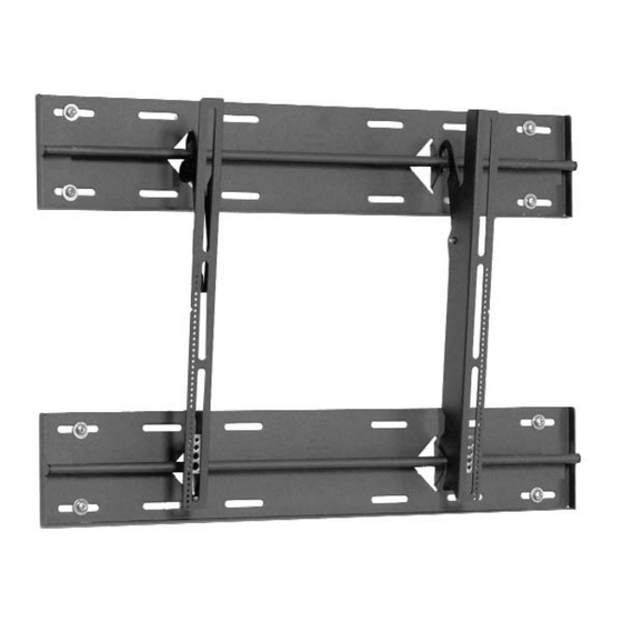
Parts List NOTE: This mount is shipped with all installation hardware and components. Make sure that none of these parts are missing and/ or damaged before beginning installation. If there are parts missing and/or damaged, please stop and contact Premier Mounts (800) 368-9700. Wall Plates (Qty 2) Mounting Brackets (Qty 2) -
Page 5: Locating The Center Of The Display
PWM-T210 Locating the Center of the Display CAUTION: Proper installation procedure by qualified personnel as outlined in the installation instructions must be adhered to. Failure to do so could result in serious personal injury and possible damage to the flat panel. -
Page 6: Securing The Mounting Brackets
Align the Mounting Brackets Figure 4 4. Match the center of viewing guide with the center line you marked in step 1 (Figure 4). Securing the Mounting Brackets The Griplates™ have M4, M5, M6 and M8 hole patterns to fit the hardware that your flat panel requires. NOTE: Your plasma uses M8 x 20 or M6 x 12 Phillips screws, use the M8, or M6, mounting points. -
Page 7: Marking The Wall
PWM-T210 Marking the Wall Figure 7 Align the center viewing port from the carton template to the wall. Match the center of viewing port to the center of viewing height desired (Figure 7). Marking the Bottom Mounting Points CAUTION: The lag bolts must be secured to the center of a stud. Use a commercially available stud finder to locate the studs nearest to your center viewing mark. -
Page 8: Securing The Lower Wall Plate
Secure the plate using the provided lag bolts (Figure 14). CAUTION: Do NOTE: CHECK THE MOUNT FOR PROPER TIGHTNESS AND SECURITY. PWM-T210 Marked Wall Template Figure 12 Power Source Area Wall Plates... -
Page 9: Mounting The Display
PWM-T210 Mounting the Display WARNING: AT LEAST (2) QUALIFIED PERSONNEL ARE STRONGLY RECOMMENDED FOR INSTALLATION OF THIS PRODUCT. FAILURE TO DO SO COULD RESULT IN SERIOUS INJURY AND POSSIBLE DAMAGE TO THE FLAT PANEL. Raise the flat panel with the mounting brackets secured to the flat panel and insert the top and bottom hooks from each bracket to the rods from the wall plates (Figure 15). -
Page 10: Securing The Display
(2) M6 x 12mm Safety Knobs, push the flat panel back to it's flat position and loosen or remove the two (2) M6 x 30 lateral shift screws and lift the unit of the wall. Page 10 M6 x 12mm M6 x 12mm Safety Knob Safety Knob Figure 17 PWM-T210 Installation Instructions... -
Page 11: Technical Specifications
PWM-T210 Technical Specifications Dimensions shown in (mm)/inches. Warranty All Premier Mounts products carry a limited lifetime warranty from ship date against defects in materials and workmanship. Premier Mounts is not liable for improper installation that results in damage to mounts, adapters, display equipment or personal injury.