NEC Aspila EX Hardware Manual
Hide thumbs
Also See for Aspila EX:
- Quick reference manual (8 pages) ,
- Quick reference manual (17 pages) ,
- Feature manual (1098 pages)
Table of Contents
Advertisement
Advertisement
Table of Contents

Related Manuals for NEC Aspila EX


Summary of Contents for NEC Aspila EX
- Page 1 CÔNG TY VIỄN THÔNG VIỆT PRO Chuyên phân phối tổng đài NEC http://vietpro.com.vn 1. Installing Cabinets 2. PCB Installation and Startup 3. Installing Extensions and Trunks 4. Optional Equipment 5. Data and SMDR 6. LAN Connection 7. Specifications and Parts Hardware Manual 00.24...
- Page 2 This manual has been developed by NEC Infrontia Asia Pacific Sdn. Bhd. It is intended for the use of its customers and service personnel, and should be read in its entirety before attempting to install or program the system. Any comments or suggestions for improving this manual would be appreciated.
-
Page 3: Table Of Contents
CÔNG TY VIỄN THÔNG VIỆT PRO Chuyên phân phối tổng đài NEC http://vietpro.com.vn Table of Contents Table of Contents Section 1: Installing the Main and Expansion Cabinets1-1 GENERAL PRECAUTIONS1-1 GETTING STARTED1-2 Additional parts supplied with the Aspila EX1-2 INSTALLING THE MAIN CABINET1-3... - Page 4 CÔNG TY VIỄN THÔNG VIỆT PRO Chuyên phân phối tổng đài NEC http://vietpro.com.vn Table of Contents BRI (2/4/8BRIU) Interface PCB (Figure 2-15)2-34 PRI (1PRIU) Interface PCB (Figure 2-16)2-37 In-Skin Server/Router (APSU) PCB (Figure 2-17)2-40 LAN 8-Port Switching Hub (8SHUBU) PCB (Figure 2-18)2-43...
- Page 5 CÔNG TY VIỄN THÔNG VIỆT PRO Chuyên phân phối tổng đài NEC http://vietpro.com.vn Table of Contents Installing a Door Box (Figure 4-10, Figure 4-11)4-7 DSS CONSOLE4-10 Using a DSS Console (Figure 4-12 - Figure 4-13)4-10 EXTERNAL PAGING4-13 External Page (Figure 4-14, Figure 4-15)4-13...
- Page 6 CÔNG TY VIỄN THÔNG VIỆT PRO Chuyên phân phối tổng đài NEC http://vietpro.com.vn Table of Contents Using LANs6-1 Installing a LAN Device or VoIP Telephone6-6 Section 7: Specifications and Parts List7-1 SYSTEM SPECIFICATIONS7-1 PARTS LIST7-8 Table of Contents Aspila EX Hardware...
-
Page 7: Installing The Main And Expansion Cabinets1
CÔNG TY VIỄN THÔNG VIỆT PRO Chuyên phân phối tổng đài NEC http://vietpro.com.vn Section 1: Installing the Cabinets Section 1: Installing the Cabinets Section 1: Installing the Cabinets Section 1: Installing the Main and Expansion Cabinets GENERAL PRECAUTIONS • To avoid shock or equipment damage, do not plug in or turn the system power on before complet- ing the installation process. -
Page 8: Parts
The Aspila EX Technical CD contains all the manuals required to install the Aspila EX system. • Aspila EX Hardware Manual How to install the parts of the Aspila EX system includes how to make connection to all ports within the system. •... -
Page 9: Installing The Main Cabinet1
CÔNG TY VIỄN THÔNG VIỆT PRO Chuyên phân phối tổng đài NEC http://vietpro.com.vn Section 1: Installing the Cabinets INSTALLING THE MAIN CABINET Unpacking Unpack the equipment and check it against your equipment lists. Inspect for physical damage. If you are not sure about a component’s function, review the information for the component within this man- ual. -
Page 10: Removing The Front Cover (Figure 1-1)1
CÔNG TY VIỄN THÔNG VIỆT PRO Chuyên phân phối tổng đài NEC http://vietpro.com.vn Section 1: Installing the Cabinets Removing the Front Cover (Figure 1-1) Position the cabinet on the floor near the MDF within 2 metres of the dedicated AC outlet. -
Page 11: Removing The Side Panels (Figure 1-2)1
CÔNG TY VIỄN THÔNG VIỆT PRO Chuyên phân phối tổng đài NEC http://vietpro.com.vn Section 1: Installing the Cabinets Removing the Side Panels (Figure 1-2) Loosen the side panel retaining screws located on the front of the cabinet. Remove the side panel covers of the Main Cabinet by pulling out slightly then moving it towards the back of the cabinet to unhook the panel. -
Page 12: Using
CÔNG TY VIỄN THÔNG VIỆT PRO Chuyên phân phối tổng đài NEC http://vietpro.com.vn Section 1: Installing the Cabinets Securing the Main Cabinet to the Floor (Figure 1-3 - Figure 1-7) Install the wall bracket on the floor providing the appropriate spacing as shown below. - Page 13 CÔNG TY VIỄN THÔNG VIỆT PRO Chuyên phân phối tổng đài NEC http://vietpro.com.vn Section 1: Installing the Cabinets Remove the 2 screws from the front of the mounting bracket. Figure 1-5: REMOVE THE SCREWS FROM THE MOUNTING BRACKET Aspila EX Hardware Manual...
- Page 14 CÔNG TY VIỄN THÔNG VIỆT PRO Chuyên phân phối tổng đài NEC http://vietpro.com.vn Section 1: Installing the Cabinets Place the cabinet on the secured mounting bracket and slide backwards. Figure 1-6: ATTACHING THE CABINET TO THE MOUNTING BRACKET Section 1: Installing the Cabinets...
- Page 15 CÔNG TY VIỄN THÔNG VIỆT PRO Chuyên phân phối tổng đài NEC http://vietpro.com.vn Section 1: Installing the Cabinets Secure the cabinet to the mounting bracket by reinstalling the two screws removed from the mounting bracket in step 2. Figure 1-7: REINSTALL SCREWS...
-
Page 16: Securing The Main Cabinet To The Wall (Figure 1-8 - Figure 1-12)1
CÔNG TY VIỄN THÔNG VIỆT PRO Chuyên phân phối tổng đài NEC http://vietpro.com.vn Section 1: Installing the Cabinets Securing the Main Cabinet to the Wall (Figure 1-8 - Figure 1-12) Install the wall bracket to the wall providing the appropriate spacing as shown below. The two top key-hole screws should protrude from the wall about 3mm to allow the bracket to slide over the screw heads. - Page 17 CÔNG TY VIỄN THÔNG VIỆT PRO Chuyên phân phối tổng đài NEC http://vietpro.com.vn Section 1: Installing the Cabinets Remove the two screws from the back of the cabinet. Figure 1-9: REMOVE THE SCREWS FROM THE CABINET Hook the mounting bracket onto the back of the cabinet.
- Page 18 CÔNG TY VIỄN THÔNG VIỆT PRO Chuyên phân phối tổng đài NEC http://vietpro.com.vn Section 1: Installing the Cabinets Lift the cabinet into position and slide the mounting bracket over the screws attached to the wall. Figure 1-11: ATTACHING THE CABINET TO THE MOUNTING BRACKET Secure the cabinet to the wall by inserting the two screws into the bottom half of the mounting bracket.
-
Page 19: Securing The Main Cabinet To A Rack (Figure 1-13 - Figure 1-17)1
CÔNG TY VIỄN THÔNG VIỆT PRO Chuyên phân phối tổng đài NEC http://vietpro.com.vn Section 1: Installing the Cabinets Securing the Main Cabinet to a Rack (Figure 1-13 - Figure 1-17) Install the 19” rack mount bracket. The 19” rack mount bracket is not supplied with the cabi- net and must be ordered seperately. - Page 20 CÔNG TY VIỄN THÔNG VIỆT PRO Chuyên phân phối tổng đài NEC http://vietpro.com.vn Section 1: Installing the Cabinets Remove the two screws from the front of the rack mount bracket. Figure 1-14: REMOVE THE SCREWS FROM THE RACK 1-14 Section 1: Installing the Cabinets...
- Page 21 CÔNG TY VIỄN THÔNG VIỆT PRO Chuyên phân phối tổng đài NEC http://vietpro.com.vn Section 1: Installing the Cabinets Connect the Earth ground wire to the cabinet. See GROUNDING THE CABINETS on page 1- 32 for complete details on grounding the system.
- Page 22 CÔNG TY VIỄN THÔNG VIỆT PRO Chuyên phân phối tổng đài NEC http://vietpro.com.vn Section 1: Installing the Cabinets Figure 1-16: INSTALLING THE CABINET IN THE RACK 1-16 Section 1: Installing the Cabinets Aspila EX Hardware...
- Page 23 CÔNG TY VIỄN THÔNG VIỆT PRO Chuyên phân phối tổng đài NEC http://vietpro.com.vn Section 1: Installing the Cabinets Replace the screws in the front of the rack which were removed in step 2. Figure 1-17: SECURING THE CABINET TO THE RACK...
-
Page 24: Installing An Expansion Cabinet1
CÔNG TY VIỄN THÔNG VIỆT PRO Chuyên phân phối tổng đài NEC http://vietpro.com.vn Section 1: Installing the Cabinets INSTALLING AN EXPANSION CABINET Expansion Cabinet The Expansion Cabinet uses an expansion bracket which attaches to the top cover of the Main Cabinet. - Page 25 CÔNG TY VIỄN THÔNG VIỆT PRO Chuyên phân phối tổng đài NEC http://vietpro.com.vn Section 1: Installing the Cabinets Place the expansion bracket on the top of the main cabinet. Using the screws provided with the expansion bracket, secure the bracket to the top of the main cabinet.
- Page 26 CÔNG TY VIỄN THÔNG VIỆT PRO Chuyên phân phối tổng đài NEC http://vietpro.com.vn Section 1: Installing the Cabinets Remove the 2 screws from the back of the expansion cabinet. Figure 1-20: REMOVE THE SCREWS FROM THE CABINET Hook the mounting bracket onto the back of the expansion cabinet.
- Page 27 CÔNG TY VIỄN THÔNG VIỆT PRO Chuyên phân phối tổng đài NEC http://vietpro.com.vn Section 1: Installing the Cabinets Figure 1-22: ATTACHING THE EXPANSION CABINET TO THE MOUNTING BRACKET Aspila EX Hardware Manual Section 1: Installing the Cabinets...
- Page 28 CÔNG TY VIỄN THÔNG VIỆT PRO Chuyên phân phối tổng đài NEC http://vietpro.com.vn Section 1: Installing the Cabinets Secure the expansion cabinet to the wall using four screws. Figure 1-23: SECURE MOUNTING BRACKET TO THE WALL 1-22 Section 1: Installing the Cabinets...
- Page 29 CÔNG TY VIỄN THÔNG VIỆT PRO Chuyên phân phối tổng đài NEC http://vietpro.com.vn Section 1: Installing the Cabinets Secure the expansion cabinet to the main cabinet by reinstalling the two screws removed from the expansion bracket in step 1. Figure 1-24: REINSTALL SCREWS On the inside of the front covers, loosen the screws for the top or bottom shutters (the top shutter for the main cabinet cover, bottom for expansion cabinet cover).
- Page 30 CÔNG TY VIỄN THÔNG VIỆT PRO Chuyên phân phối tổng đài NEC http://vietpro.com.vn Section 1: Installing the Cabinets 10. Slide the shutters to the left to allow a pass-through for the EXIFU cables. Retighten these screws. Figure 1-25: MOVING THE FRONT PANEL SHUTTERS 11.
- Page 31 CÔNG TY VIỄN THÔNG VIỆT PRO Chuyên phân phối tổng đài NEC http://vietpro.com.vn Section 1: Installing the Cabinets Expanding a Rack Mounted System (Figure 1-27 - Figure 1-34) Remove the two screws from the expansion bracket. Figure 1-27: REMOVING THE SCREWS FROM THE BRACKET Place the expansion bracket on the top of the base cabinet.
- Page 32 CÔNG TY VIỄN THÔNG VIỆT PRO Chuyên phân phối tổng đài NEC http://vietpro.com.vn Section 1: Installing the Cabinets Connect the earth ground wire to the expansion cabinet. See GROUNDING THE CABINETS on page 1-32 for complete details on grounding the system.
- Page 33 CÔNG TY VIỄN THÔNG VIỆT PRO Chuyên phân phối tổng đài NEC http://vietpro.com.vn Section 1: Installing the Cabinets Install the expansion cabinet onto the base cabinet. The expansion cabinet will require 400mm (9U) of height within the rack. See ATTACHING THE EXPANSION CABINET TO THE MOUNTING BRACKET on page 1-21 for details of fitting the expansion cabinet onto the base cabinet.
- Page 34 CÔNG TY VIỄN THÔNG VIỆT PRO Chuyên phân phối tổng đài NEC http://vietpro.com.vn Section 1: Installing the Cabinets Place the cabinets in the rack, making sure the hooks on the mounting bracket are inserted into the back of the cabinet, securing it in place.
- Page 35 CÔNG TY VIỄN THÔNG VIỆT PRO Chuyên phân phối tổng đài NEC http://vietpro.com.vn Section 1: Installing the Cabinets Secure the two cabinets by tightening the belt around both cabinets. Figure 1-32: SECURING THE CABINETS TOGETHER Aspila EX Hardware Manual Section 1: Installing the Cabinets...
- Page 36 CÔNG TY VIỄN THÔNG VIỆT PRO Chuyên phân phối tổng đài NEC http://vietpro.com.vn Section 1: Installing the Cabinets 10. Replace the screws in the front of the rack. Figure 1-33: SECURING THE CABINETS TO THE RACK 11. On the inside of the front cover, loosen the screws for the top and bottom shutters.
-
Page 37: Power Supplies In The Main And Expansion Cabinets1
CÔNG TY VIỄN THÔNG VIỆT PRO Chuyên phân phối tổng đài NEC http://vietpro.com.vn Section 1: Installing the Cabinets REPLACING THE POWER SUPPLY Power Supplies in the Main and Expansion Cabinets Caution Double Pole/Neutral Fusing (power supply fuses located at both the L and N side) The power supply is installed in the PS1/PS2 slots on the left side of the cabinet. -
Page 38: Grounding The Cabinets1
CÔNG TY VIỄN THÔNG VIỆT PRO Chuyên phân phối tổng đài NEC http://vietpro.com.vn Section 1: Installing the Cabinets GROUNDING THE CABINETS Connecting the System Ground (Figure 1-35) The SG, PBXG, ETH and FG ground lugs are located on the right side of the cabinet. The side panel must be removed in order to access them. - Page 39 CÔNG TY VIỄN THÔNG VIỆT PRO Chuyên phân phối tổng đài NEC http://vietpro.com.vn Section 1: Installing the Cabinets The ground lug descriptions are as follows: • SG (Signal Ground) The plus side of the supplied voltage to single line telephones in the PBX requires a connection to the earth.
-
Page 40: Completing The Installation1
CÔNG TY VIỄN THÔNG VIỆT PRO Chuyên phân phối tổng đài NEC http://vietpro.com.vn Section 1: Installing the Cabinets COMPLETING THE INSTALLATION Reinstalling the Front Cover (Figure 1-36) Line up the brackets on the front cover with the slots in the cabinet and insert the cover. - Page 41 CÔNG TY VIỄN THÔNG VIỆT PRO Chuyên phân phối tổng đài NEC http://vietpro.com.vn Section 1: Installing the Cabinets The each cabinet has three cable pass-throughs - one on the left panel, right panel, and rear panel. The shutters on the unused pass-throughs should be closed in order to help keep dust out of the cabinet.
- Page 42 CÔNG TY VIỄN THÔNG VIỆT PRO Chuyên phân phối tổng đài NEC http://vietpro.com.vn Section 1: Installing the Cabinets 1-36 Section 1: Installing the Cabinets Aspila EX Hardware...
-
Page 43: Pcb Layout2
CÔNG TY VIỄN THÔNG VIỆT PRO Chuyên phân phối tổng đài NEC http://vietpro.com.vn Section 2: PCB Installation and Startup Section 2: PCB Installation and Startup Section 2: PCB Installation and Startup PCB LAYOUT PCB Location Determine the slot position for each PCB in the Main Cabinet: •... -
Page 44: Order Of Installing Extension Pcbs2
CÔNG TY VIỄN THÔNG VIỆT PRO Chuyên phân phối tổng đài NEC http://vietpro.com.vn Section 2: PCB Installation and Startup Order of Installing Extension PCBs The order that the station PCBs (e.g. ESIU and SLIU) are physically inserted determines the numbering plan. -
Page 45: Pcb Installation2
CÔNG TY VIỄN THÔNG VIỆT PRO Chuyên phân phối tổng đài NEC http://vietpro.com.vn Section 2: PCB Installation and Startup PCB INSTALLATION Handling the PCBs The PCBs are sensitive to static discharge. To minimize static discharge, keep PCBs in static free bags when not installed. -
Page 46: Removing An Extension Or Trunk Pcb2
CÔNG TY VIỄN THÔNG VIỆT PRO Chuyên phân phối tổng đài NEC http://vietpro.com.vn Section 2: PCB Installation and Startup Insert the PCB within the guide rail and push the PCB securely into position. After installing all the PCBs, the PCB retaining bar should be moved back into position and the screws should be tightened. -
Page 47: Where To Install The Pcbs2
CÔNG TY VIỄN THÔNG VIỆT PRO Chuyên phân phối tổng đài NEC http://vietpro.com.vn Section 2: PCB Installation and Startup Where to Install the PCBs Maximum Configuration: 200 Trunks 512 Extensions Including IP (256 maximum digital/analogue extensions) The system’s universal architecture gives you great flexibility when installing PCBs. You can install a PCB in any slot, provided you follow the guidelines in the chart below. -
Page 48: Central Processing Unit (Ntcpu) Pcb (Figure 2-3)2
Central Processing Unit (NTCPU) PCB (Figure 2-3) The NTCPU controls all the functions and operations of the Aspila EX system using the system soft- ware loaded into the NTCPU memory. One 32-bit NTCPU PCB must be installed in the CPU slot in the Main Cabinet. - Page 49 CÔNG TY VIỄN THÔNG VIỆT PRO Chuyên phân phối tổng đài NEC http://vietpro.com.vn Section 2: PCB Installation and Startup Figure 2-3: CPRU PCB Aspila EX Hardware Manual Section 2: PCB Installation and Startup...
- Page 50 CÔNG TY VIỄN THÔNG VIỆT PRO Chuyên phân phối tổng đài NEC http://vietpro.com.vn Section 2: PCB Installation and Startup NTCPU Options There are three NTCPU PCB’s available. IP1E-NTCPU-A0 :Maximum 72 trunk/extension ports and limited features. IP1E-NTCPU-A1 :Maximum 128 trunk/extension ports and limited featues.
- Page 51 CÔNG TY VIỄN THÔNG VIỆT PRO Chuyên phân phối tổng đài NEC http://vietpro.com.vn Section 2: PCB Installation and Startup Switch Settings and LED Indications Switch Switch Operation Setting SW1 - Load Switch With a system restart or a system reset while holding the SW1...
-
Page 52: Connector Pin-Outs On Ntcpu2
CÔNG TY VIỄN THÔNG VIỆT PRO Chuyên phân phối tổng đài NEC http://vietpro.com.vn Section 2: PCB Installation and Startup LED Indication Status RUN (LED1) LED0 LED2 LED3 LED4 Blinking Flash memory data error Blinking Blinking Blinking Blinking Reading error of system program... - Page 53 CÔNG TY VIỄN THÔNG VIỆT PRO Chuyên phân phối tổng đài NEC http://vietpro.com.vn Section 2: PCB Installation and Startup RJ61 Cable Connector - CN16 (External MOH Source/External Paging) NTCPRU Modular Connector Signal Connector Pin No. EXMOH EXPG EXPG EXMOH •...
- Page 54 CÔNG TY VIỄN THÔNG VIỆT PRO Chuyên phân phối tổng đài NEC http://vietpro.com.vn Section 2: PCB Installation and Startup CPRU Installation (Figure 2-4) Install the battery on the CPRU. The polarity “+” symbol must be on top. Install the DSPDBU daughter board if required. Refer to DSPDB Daughter Board (Figure 2-6, Figure 2-7) (page 2-15).
- Page 55 CÔNG TY VIỄN THÔNG VIỆT PRO Chuyên phân phối tổng đài NEC http://vietpro.com.vn Section 2: PCB Installation and Startup To Perform a Hot Start: System software loaded from flash memory and the customer data is loaded from RAM memory. Power off the main cabinet PSU. Push and release the switch on the PSU.
-
Page 56: Expansion (Exifu) Pcb (Figure 2-5)2
CÔNG TY VIỄN THÔNG VIỆT PRO Chuyên phân phối tổng đài NEC http://vietpro.com.vn Section 2: PCB Installation and Startup Expansion (EXIFU) PCB (Figure 2-5) The EXIFU PCB provides a connection from the main cabinet to the expansion cabinet. This connec- tion is required with any 2-cabinet setup. -
Page 57: Dspdb Daughter Board (Figure 2-6, Figure 2-7)2
CÔNG TY VIỄN THÔNG VIỆT PRO Chuyên phân phối tổng đài NEC http://vietpro.com.vn Section 2: PCB Installation and Startup DSPDB Daughter Board (Figure 2-6, Figure 2-7) The DSPDB provides additional DSP resources as well as VRS (Voice Response System). This daugh- ter board is mounted on the NTCPU and provides: •... - Page 58 CÔNG TY VIỄN THÔNG VIỆT PRO Chuyên phân phối tổng đài NEC http://vietpro.com.vn Section 2: PCB Installation and Startup To Upgrade the DSPDB Compact Flash Card: With the system power off, remove the NTCPU. Remove the compact flash card from the DSPDB daughter board.
-
Page 59: Digital Station (8/16Esiu) Pcb (Figure 2-8)2
CÔNG TY VIỄN THÔNG VIỆT PRO Chuyên phân phối tổng đài NEC http://vietpro.com.vn Section 2: PCB Installation and Startup Digital Station (8/16ESIU) PCB (Figure 2-8) The ESIU PCB provides: • 8 (8ESIU) or 16 (16ESIU) digital extension circuits (used for digital telephones, DSS consoles, 1SLTAD adapters, 2PGDAD adapters) •... - Page 60 CÔNG TY VIỄN THÔNG VIỆT PRO Chuyên phân phối tổng đài NEC http://vietpro.com.vn Section 2: PCB Installation and Startup To install the ESIU PCB: Set the run/block switch to block, DOWN . Install the ESIU into a slot. Note that the white PCB Pull Tab should always be positioned closest to the top of the cabinet.
-
Page 61: Analogue Station (8Sliu) Pcb (Figure 2-9)2
CÔNG TY VIỄN THÔNG VIỆT PRO Chuyên phân phối tổng đài NEC http://vietpro.com.vn Section 2: PCB Installation and Startup Analogue Station (8SLIU) PCB (Figure 2-9) The 8SLIU PCB provides: • 8 analogue extension ports (used for analogue telephones, fax machines, analogue modems and connection to voice mail systems) •... - Page 62 CÔNG TY VIỄN THÔNG VIỆT PRO Chuyên phân phối tổng đài NEC http://vietpro.com.vn Section 2: PCB Installation and Startup Installing an 8SLIU PCB: Set the run/block switch to block, DOWN . If the 8SLIDB is to be used, install this prior to inserting the 8SLIU PCB into the cabinet.
-
Page 63: Analogue Station (8Slidb) Daughter Board (Figure 2-10 - Figure 2-11)2
CÔNG TY VIỄN THÔNG VIỆT PRO Chuyên phân phối tổng đài NEC http://vietpro.com.vn Section 2: PCB Installation and Startup Analogue Station (8SLIDB) Daughter Board (Figure 2-10 - Figure 2-11) The 8SLIDB daughter board provides: • 8 analogue extension ports (used for... - Page 64 CÔNG TY VIỄN THÔNG VIỆT PRO Chuyên phân phối tổng đài NEC http://vietpro.com.vn Section 2: PCB Installation and Startup Installing an 8SLIDB Daughter Board: Included with the 8SLIDB are three plastic spacers and two metal spacers. The plastic spacers are installed diagonally across the daughter board. The metal spacers are then installed in the remaining two corners.
-
Page 65: Analogue Trunk (4/8Coiu) Pcb (Figure 2-12)2
CÔNG TY VIỄN THÔNG VIỆT PRO Chuyên phân phối tổng đài NEC http://vietpro.com.vn Section 2: PCB Installation and Startup Analogue Trunk (4/8COIU) PCB (Figure 2-12) There are two different types of the COIU PCB. One providing ground start trunks - the other is for loop start trunks only. - Page 66 CÔNG TY VIỄN THÔNG VIỆT PRO Chuyên phân phối tổng đài NEC http://vietpro.com.vn Section 2: PCB Installation and Startup Connector Pin-Outs on COIU PCB RJ61 Cable Connector - CN3, Trunks The CN3 and CN5 connectors Pin No. Connection Circuit 4 - Tip...
- Page 67 CÔNG TY VIỄN THÔNG VIỆT PRO Chuyên phân phối tổng đài NEC http://vietpro.com.vn Section 2: PCB Installation and Startup Installing the Analogue Trunk PCB: Set the run/block switch to block, DOWN . Install the COIU into a slot. Note that the white PCB Pull Tab should always be positioned closest to the top of the cabinet.
-
Page 68: Direct Inward Dial (Did) (4/8Diopu) Pcb (Figure 2-13)2
CÔNG TY VIỄN THÔNG VIỆT PRO Chuyên phân phối tổng đài NEC http://vietpro.com.vn Section 2: PCB Installation and Startup Direct Inward Dial (DID) (4/8DIOPU) PCB (Figure 2-13) The 4/8DIOPU PCB supports the analogue DID and single line telephone interface functions (such as Off-Premise Extension). - Page 69 CÔNG TY VIỄN THÔNG VIỆT PRO Chuyên phân phối tổng đài NEC http://vietpro.com.vn Section 2: PCB Installation and Startup Installing the Direct Inward Dial PCB: Set the run/block switch to block, DOWN . Install the DIOPU PCB into a slot.
-
Page 70: Tie Line (4Tliu) Pcb (Figure 2-14)2
When a router or multiplexer is connected instead of a trunk, the SG terminal of the router or mul- tiplexer must be connected to the PBXG and FG grounding terminals on the Aspila EX cabinet. When a trunk is connected, the PBXG and FG terminals must be connected to Earth. If the PBXG terminal is not connected correctly, the signal may fail. - Page 71 CÔNG TY VIỄN THÔNG VIỆT PRO Chuyên phân phối tổng đài NEC http://vietpro.com.vn Section 2: PCB Installation and Startup Connector Pin-Outs on 4TLIU PCB RJ61 Cable Connector - 2-Wire E&M, CN100 - CN400 Pin No. Connection Description Ground wire for control...
- Page 72 CÔNG TY VIỄN THÔNG VIỆT PRO Chuyên phân phối tổng đài NEC http://vietpro.com.vn Section 2: PCB Installation and Startup Signaling Method for Circuit Types 2-30 Section 2: PCB Installation and Startup Aspila EX Hardware Man-...
- Page 73 CÔNG TY VIỄN THÔNG VIỆT PRO Chuyên phân phối tổng đài NEC http://vietpro.com.vn Section 2: PCB Installation and Startup Aspila EX Hardware Manual Section 2: PCB Installation and Startup 2-31...
- Page 74 CÔNG TY VIỄN THÔNG VIỆT PRO Chuyên phân phối tổng đài NEC http://vietpro.com.vn Section 2: PCB Installation and Startup Voice Signal Connection for all Circuit Types 2-32 Section 2: PCB Installation and Startup Aspila EX Hardware Man-...
- Page 75 CÔNG TY VIỄN THÔNG VIỆT PRO Chuyên phân phối tổng đài NEC http://vietpro.com.vn Section 2: PCB Installation and Startup Installing the 4TLIU PCB: Set the run/block switch to block, DOWN . Set the straps for either the 2-wire or 4-wire (see Figure 2-14).
-
Page 76: Bri (2/4/8Briu) Interface Pcb (Figure 2-15)2
The first 4 circuits (1-4) are supplied with DC power from the Aspila EX system when set to S-Bus mode in program 10-03. If the last four circuits (5-8) are to be used for S-Bus, they must use ISDN telephone sets which provide their own local power supply as the system does not provide DC power to these circuits. - Page 77 SW800 Termination resistor When T-Bus with Point-to-Multipoint is selected and if is OFF the Aspila EX system is not connected to the last port of the Bus connection, this switch should be OFF. CN102 With S-Bus selected, If S-Bus is selected, this switch should be ON if the...
- Page 78 CÔNG TY VIỄN THÔNG VIỆT PRO Chuyên phân phối tổng đài NEC http://vietpro.com.vn Section 2: PCB Installation and Startup To install a BRI Interface PCB: Set the run/block switch to block, DOWN. Set the SWn02 jumpers on the BRI PCB for either T-Bus or S-Bus.
-
Page 79: Pri (1Priu) Interface Pcb (Figure 2-16)2
CÔNG TY VIỄN THÔNG VIỆT PRO Chuyên phân phối tổng đài NEC http://vietpro.com.vn Section 2: PCB Installation and Startup PRI (1PRIU) Interface PCB (Figure 2-16) For ISDN Primary Rate Interface (PRI) applications, install a PRI Interface PCB. This PCB has a sin- gle 32-channel (30B plus 2D) 2.048Mb/s digital signal circuit which can be configured for either PRI... - Page 80 CÔNG TY VIỄN THÔNG VIỆT PRO Chuyên phân phối tổng đài NEC http://vietpro.com.vn Section 2: PCB Installation and Startup Connector Pin-Outs on 1PRIU PCB RJ45 Cable Connector - CN3 S-Bus Connection Pin No. Connection RJ45 Cable Connector - CN3 T-Bus Connection Pin No.
- Page 81 CÔNG TY VIỄN THÔNG VIỆT PRO Chuyên phân phối tổng đài NEC http://vietpro.com.vn Section 2: PCB Installation and Startup To install a PRI Interface PCB: Set the run/block switch to block, DOWN. Make sure the SW100 switch on the PRI Interface PCB is set to 2.048Mb/s (PRI).
-
Page 82: In-Skin Server/Router (Apsu) Pcb (Figure 2-17)2
Section 2: PCB Installation and Startup In-Skin Server/Router (APSU) PCB (Figure 2-17) The In-Skin Server/Router PCB provides server functionality within the Aspila EX system with a hard drive or IDE flash memory. The hard disk or IDE flash memory can provide an operating system and application software ability which can be used with CTI applications. - Page 83 CÔNG TY VIỄN THÔNG VIỆT PRO Chuyên phân phối tổng đài NEC http://vietpro.com.vn Section 2: PCB Installation and Startup LED Indications Function Operation Status Status LED 1 Status PCB Status Green Initializing, downloading the software or (Live) Steady shutting down the server, but not ready for PCB to be removed.
- Page 84 CÔNG TY VIỄN THÔNG VIỆT PRO Chuyên phân phối tổng đài NEC http://vietpro.com.vn Section 2: PCB Installation and Startup In-Skin Server/Router PCB Installation (Figure 2-17) Install the battery on the APSU PCB. The polarity “+” symbol must be on top.
-
Page 85: Lan 8-Port Switching Hub (8Shubu) Pcb (Figure 2-18)2
The 16VOIPU PCB, which is required in order for IP telephones to communicate with non-VoIP Aspila EX phones, as well as to place or receive outside calls, must be connected to either an external switching hub or to the 8SHUBU PCB. - Page 86 CÔNG TY VIỄN THÔNG VIỆT PRO Chuyên phân phối tổng đài NEC http://vietpro.com.vn Section 2: PCB Installation and Startup Installing the 8SHUBU: Set the run/block switch to block, DOWN. Plug the LAN 8-Port Switching Hub PCB into any universal slot.
-
Page 87: Voip (16Voipu) Pcb (Figure 2-19)2
PCM-based digital circuit, this PCB converts the IP packet signal into a PCM signal format and connects to the PCM time division switch. The 16VOIPU PCB is required in order for IP telephones to communicate with non-VoIP Aspila EX phones, as well as to place or receive outside calls. -
Page 88: Voip (Voipdb) Daughter Board (Figure 2-20 - Figure 2-21)2
CÔNG TY VIỄN THÔNG VIỆT PRO Chuyên phân phối tổng đài NEC http://vietpro.com.vn Section 2: PCB Installation and Startup Installing the VoIP PCB: Set the run/block switch to block, DOWN . If the VOIPDB is to be used, install this prior to inserting the 16VOIPU PCB into the cab- inet. - Page 89 CÔNG TY VIỄN THÔNG VIỆT PRO Chuyên phân phối tổng đài NEC http://vietpro.com.vn Section 2: PCB Installation and Startup VoIP (VOIPDB) Daughter Board (Figure 2-20 - Figure 2-21) The VOIPDB daughter board provides: • 16 channels • Connector for the 16VOIPU PCB (com-...
-
Page 90: Pcb Startup2
When starting the system for the first time, hold the LOAD button on the NTCPU and turn the AC Power Panel switch to ON. After approximately 3 seconds, release the LOAD button. This performs a cold start on the Aspila EX system to make sure you’re starting with a defaulted system. -
Page 91: Initial Installation Of Trunk Pcbs2
CÔNG TY VIỄN THÔNG VIỆT PRO Chuyên phân phối tổng đài NEC http://vietpro.com.vn Section 2: PCB Installation and Startup Initial Installation of Trunk PCBs When first installing the system: Set the run/block switch DOWN on all COIU-LS1, COIU-LG1, 4TLIU, DIOPU, 1PRIU or BRIU PCBs. -
Page 92: System Startup2
When starting the system for the first time, hold the LOAD button on the NTCPU and turn the AC Power Panel switch to ON. After approximately 3 seconds, release the LOAD button. This performs a cold start on the Aspila EX system to make sure you’re starting with a defaulted system. -
Page 93: Initial Programming (Figure 2-22)2
Web Programming Refer to the PCPro/WebPro Installation Manual, for complete installation details. Refer to the Aspila EX Software Manual for complete details on programming. Entering the Programming Mode Enter the system programming mode at any system phone with an LCD display: Press CALL1. -
Page 94: Setting Up Extension Circuit Types2
CÔNG TY VIỄN THÔNG VIỆT PRO Chuyên phân phối tổng đài NEC http://vietpro.com.vn Section 2: PCB Installation and Startup Setting Up Extension Circuit Types Run Program 10-03 to set up extension circuit types as required. The system will automatically detect and assign most circuit types when the device is connected. -
Page 95: Making Test Calls2
CÔNG TY VIỄN THÔNG VIỆT PRO Chuyên phân phối tổng đài NEC http://vietpro.com.vn Section 2: PCB Installation and Startup Making Test Calls In the initial configuration: • All Programmable Function keys are line keys (e.g., key 1 is line 1). -
Page 96: Basic Troubleshooting2
CÔNG TY VIỄN THÔNG VIỆT PRO Chuyên phân phối tổng đài NEC http://vietpro.com.vn Section 2: PCB Installation and Startup Basic Troubleshooting To troubleshoot extensions: Verify the Run/Block switch is set in the RUN position for the PCB. Check and verify extension. The ESIU PCB has test points located on the top edge of the PCB. -
Page 97: Identifying Port Location2
CÔNG TY VIỄN THÔNG VIỆT PRO Chuyên phân phối tổng đài NEC http://vietpro.com.vn Section 2: PCB Installation and Startup Identifying Port Location Port information such as PCB type, port numbers, PCB status, and individual port status can be obtained from the system. To obtain a System Report containing PCB information, the system must be connected to a PC or terminal using the serial, USB, or LAN port connector on the NTCPU. -
Page 98: System Shutdown2
CÔNG TY VIỄN THÔNG VIỆT PRO Chuyên phân phối tổng đài NEC http://vietpro.com.vn Section 2: PCB Installation and Startup SYSTEM SHUTDOWN Powering Off the System Observe the following when powering off the system. • It is advisable to make a back up of the customer configuration before powering off. - Page 99 CÔNG TY VIỄN THÔNG VIỆT PRO Chuyên phân phối tổng đài NEC http://vietpro.com.vn Section 3: Installing Extensions and Trunks Section 3: Installing Extensions and Trunks Section 3: Installing Extensions and Trunks !! Important !! Install telephones as on-premise extensions only. (Otherwise, the telephones are highly susceptible to lightning strikes.)
-
Page 100: Rj61 Wiring And Pinouts3
CÔNG TY VIỄN THÔNG VIỆT PRO Chuyên phân phối tổng đài NEC http://vietpro.com.vn Section 3: Installing Extensions and Trunks RJ61 WIRING AND PINOUTS The presentation of the following PCB’s is via RJ61 sockets. • NTCPU • ESIU • SLIU/SLIDB •... -
Page 101: Specifications And Parts
CÔNG TY VIỄN THÔNG VIỆT PRO Chuyên phân phối tổng đài NEC http://vietpro.com.vn Section 3: Installing Extensions and Trunks INSTALLING EXTENSIONS Digital Extension Cabling Each digital extension requires one-pair twisted cable from the MDF to the RJ11/RJ45 socket. Refer to Section 7: Specifications and Parts List (page 7-1) for maximum cable lengths. -
Page 102: Installing Single Line Telephones3
CÔNG TY VIỄN THÔNG VIỆT PRO Chuyên phân phối tổng đài NEC http://vietpro.com.vn Section 3: Installing Extensions and Trunks INSTALLING SINGLE LINE TELEPHONES Single Line Extension Cabling Each single line extension requires one-pair twisted station cable from the MDF to the Master type line jack unit. -
Page 103: Installing Co/Pbx Lines3
CÔNG TY VIỄN THÔNG VIỆT PRO Chuyên phân phối tổng đài NEC http://vietpro.com.vn Section 3: Installing Extensions and Trunks INSTALLING CO/PBX LINES Ground Start/Loop Start Line Cabling There are four types of COIU PCB providing loop start or ground start trunks as shown in the table below. -
Page 104: Installing Bri Trunks3
CÔNG TY VIỄN THÔNG VIỆT PRO Chuyên phân phối tổng đài NEC http://vietpro.com.vn Section 3: Installing Extensions and Trunks INSTALLING BRI TRUNKS BRI Trunks Installing BRI Trunks For Trunk Mode: The BRI circuit can be plugged directly into the NT1 Termination. Use an RJ45 patch cable. -
Page 105: Installing Pri Trunks3
CÔNG TY VIỄN THÔNG VIỆT PRO Chuyên phân phối tổng đài NEC http://vietpro.com.vn Section 3: Installing Extensions and Trunks INSTALLING PRI TRUNKS PRI Trunks Installing PRI Trunks For Trunk Mode: The PRI circuit can be plugged directly into the NT1 Termination. Use an RJ45 patch cable. -
Page 106: Installing Did Trunks3
CÔNG TY VIỄN THÔNG VIỆT PRO Chuyên phân phối tổng đài NEC http://vietpro.com.vn Section 3: Installing Extensions and Trunks INSTALLING DID TRUNKS DID Trunks Installing DID Trunks : For each trunk, run one-pair cable from the PSTN Network Termination point to the DIOPU PCB. -
Page 107: Installing Tie Lines3
CÔNG TY VIỄN THÔNG VIỆT PRO Chuyên phân phối tổng đài NEC http://vietpro.com.vn Section 3: Installing Extensions and Trunks INSTALLING TIE LINES Tie Line: 4TLIU ! Important ! • When using the TLIU PCB, the PBX and Earth grounds must be connected as described on page 1-32 or the trunks will not function correctly. - Page 108 CÔNG TY VIỄN THÔNG VIỆT PRO Chuyên phân phối tổng đài NEC http://vietpro.com.vn Section 3: Installing Extensions and Trunks Installing 4-wire/8-lead Tie Lines: For each trunk, run two-pair cable from the PSTN Network Termination point to the TLIU PCB. Refer to Tie Line (4TLIU) PCB (Figure 2-14) (page 2-28) for details of the RJ61 con- nector pin outs..
-
Page 109: Testing Telephone Operation3
CÔNG TY VIỄN THÔNG VIỆT PRO Chuyên phân phối tổng đài NEC http://vietpro.com.vn Section 3: Installing Extensions and Trunks TESTING TELEPHONE OPERATION The following procedure will help you determine if a problem being experienced is due to the tele- phone or the system. Testing the operation of a system phone allows you to check the lamping of each key, the display, and tones. -
Page 110: Super Display Lcd3
CÔNG TY VIỄN THÔNG VIỆT PRO Chuyên phân phối tổng đài NEC http://vietpro.com.vn Section 3: Installing Extensions and Trunks SUPER DISPLAY LCD Positioning the Super Display LCD(Figure 3-3, Figure 3-4) The LCD on a super display system phone has two angles which it can be positioned for the best view- ing for the customer. -
Page 111: Pgdad Module4
CÔNG TY VIỄN THÔNG VIỆT PRO Chuyên phân phối tổng đài NEC http://vietpro.com.vn Aspila EXSection 4: Optional Equipment Section 4: Optional Equipment Section 4: Optional Equipment 2PGDAD MODULE Using a 2PGDAD Module (Figure 4-1 - Figure 4-8) The 2PGDAD module provides two circuits which allow connection to external terminals such as: •... -
Page 112: Led Indications4
CÔNG TY VIỄN THÔNG VIỆT PRO Chuyên phân phối tổng đài NEC http://vietpro.com.vn Section 4: Optional Equipment LED Indications Indication Note LED 1 Green LED when Flashing green LED indicates dipswitch setting CH1 in use. and programming for CH1 is conflicting. - Page 113 CÔNG TY VIỄN THÔNG VIỆT PRO Chuyên phân phối tổng đài NEC http://vietpro.com.vn Section 4: Optional Equipment Set the S3 - S6 jumpers to the proper settings for the function to be used. Channel1 Function Open Open Door Box Open...
- Page 114 CÔNG TY VIỄN THÔNG VIỆT PRO Chuyên phân phối tổng đài NEC http://vietpro.com.vn Section 4: Optional Equipment Insert the cable into the proper CN4 or CN5 location while holding down the lock button (holding down this lock button is easiest with a flat-head screwdriver). Once the cable is in place, release the lock button.
- Page 115 CÔNG TY VIỄN THÔNG VIỆT PRO Chuyên phân phối tổng đài NEC http://vietpro.com.vn Section 4: Optional Equipment 10-03. The PGDAD will then automatically configure when plugged in. 12. After plugging in the PGDAD confirm with Program 10-03 that the mode of each circuit cor- responds to the setting of the jumpers S3-S6 13.
-
Page 116: Background Music4
CÔNG TY VIỄN THÔNG VIỆT PRO Chuyên phân phối tổng đài NEC http://vietpro.com.vn Section 4: Optional Equipment BACKGROUND MUSIC Installing Background Music (Figure 4-9) Background Music (BGM) sends music from a customer-provided music source to speakers in system phones and digital single line telephones. If an extension user activates it, BGM plays whenever the user’s extension is idle. -
Page 117: Door Box4
CÔNG TY VIỄN THÔNG VIỆT PRO Chuyên phân phối tổng đài NEC http://vietpro.com.vn Section 4: Optional Equipment DOOR BOX Installing a Door Box (Figure 4-10, Figure 4-11) A 2PGDAD Module is required for this feature. The Door Box is a self-contained Intercom unit typically used to monitor an entrance door. A visitor at the door can press the Door Box call button (like a door bell). - Page 118 CÔNG TY VIỄN THÔNG VIỆT PRO Chuyên phân phối tổng đài NEC http://vietpro.com.vn Section 4: Optional Equipment Figure 4-10: SETTING THE 2PGDAD FOR A DOOR BOX Section 4: Optional Equipment Aspila EX Hardware...
- Page 119 CÔNG TY VIỄN THÔNG VIỆT PRO Chuyên phân phối tổng đài NEC http://vietpro.com.vn Section 4: Optional Equipment Figure 4-11: INSTALLING A DOOR BOX Aspila EX Hardware Manual Section 4: Optional Equipment...
-
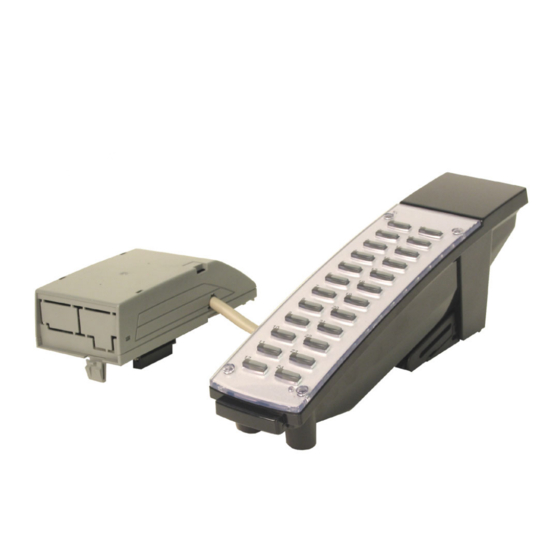
Page 120: Dss Console4
CÔNG TY VIỄN THÔNG VIỆT PRO Chuyên phân phối tổng đài NEC http://vietpro.com.vn Section 4: Optional Equipment DSS CONSOLE Using a DSS Console (Figure 4-12 - Figure 4-13) The DSS Console gives a system phone user a Busy Lamp Field (BLF) and one-button access to exten- sions, trunks and system features. - Page 121 CÔNG TY VIỄN THÔNG VIỆT PRO Chuyên phân phối tổng đài NEC http://vietpro.com.vn Section 4: Optional Equipment Installing a 110-Button DSS Console Install an RJ11 (or RJ45) socket for each 110-Button DSS Console. The socket should be within two metres of the console.
- Page 122 CÔNG TY VIỄN THÔNG VIỆT PRO Chuyên phân phối tổng đài NEC http://vietpro.com.vn Section 4: Optional Equipment Installing a 24-Button DLS Console The console should be installed on the right-hand side of the phone in order to use the fixing plate supplied with the console.
-
Page 123: External Paging4
CÔNG TY VIỄN THÔNG VIỆT PRO Chuyên phân phối tổng đài NEC http://vietpro.com.vn Section 4: Optional Equipment EXTERNAL PAGING External Page (Figure 4-14, Figure 4-15) Two external page zone/door box circuits are provided by each 2PGDAD installed. Each Door Box/exter- nal page circuit provides a dry relay contact. - Page 124 CÔNG TY VIỄN THÔNG VIỆT PRO Chuyên phân phối tổng đài NEC http://vietpro.com.vn Section 4: Optional Equipment Figure 4-14: 2PGDAD CABLE CONNECTION Note: Page amplification is not provided by the 2PGDAD module and must be accommodated by using an external page amplifier.
-
Page 125: External Paging And Page Relays4
CÔNG TY VIỄN THÔNG VIỆT PRO Chuyên phân phối tổng đài NEC http://vietpro.com.vn Section 4: Optional Equipment EXTERNAL PAGING AND PAGE RELAYS External Page Relays Two external dry contact relays are available when a 2PGDAD is installed which can be used to activate ancillary devices (i.e. -
Page 126: Headsets4
CÔNG TY VIỄN THÔNG VIỆT PRO Chuyên phân phối tổng đài NEC http://vietpro.com.vn Section 4: Optional Equipment HEADSETS Connecting a Headset A system phone user can utilise a customer-provided headset in place of the handset. Like using Handsfree, using the headset frees up the user’s hands for other work. However, Headset Operation provides privacy not available from handsfree. -
Page 127: System Phone Labeling4
SYSTEM PHONE LABELING Labeling Your Phone The Aspila EX system phones can be easily labeled by removing the clear plastic faceplate on the sys- tem phones. These labels can be printed by hand, typewriter, or by using the Aspila EX Labelmaker program. -
Page 128: Music Sources4
CÔNG TY VIỄN THÔNG VIỆT PRO Chuyên phân phối tổng đài NEC http://vietpro.com.vn Section 4: Optional Equipment MUSIC SOURCES Music on Hold (Figure 4-16, Figure 4-17) The system can provide Music on Hold from either an internally synthesized source on the NTCPU or from an external source. - Page 129 CÔNG TY VIỄN THÔNG VIỆT PRO Chuyên phân phối tổng đài NEC http://vietpro.com.vn Section 4: Optional Equipment Figure 4-17: 2PGDAD CONNECTIONS Aspila EX Hardware Manual Section 4: Optional Equipment 4-19...
-
Page 130: Night Mode Selection4
CÔNG TY VIỄN THÔNG VIỆT PRO Chuyên phân phối tổng đài NEC http://vietpro.com.vn Section 4: Optional Equipment NIGHT MODE SELECTION Night Mode Selector Switch The Night Mode Switch detects an input voltage at the NTMOD terminals of the RJ61 connector on the NTCPU card, CN17pins 2 &... -
Page 131: Optional Phone Adapters4
Section 4: Optional Equipment OPTIONAL PHONE ADAPTERS Using Adapters (Figure 4-18) Each Aspila EX system phone can have two optional adapters installed (unless an IP adapter is used). These adapters provide the system phones different capabilities, depend- ing on the adapters installed. -
Page 132: Removing The Adapter Cover (Figure 4-19)4
CÔNG TY VIỄN THÔNG VIỆT PRO Chuyên phân phối tổng đài NEC http://vietpro.com.vn Section 4: Optional Equipment Removing the Adapter Cover (Figure 4-19) With certain applications, it may be necessary to remove the cover from an adapter. First, remove the screw on the back of the adapter. -
Page 133: Ada Adapter (Figure 4-20 - Figure 4-26)4
CÔNG TY VIỄN THÔNG VIỆT PRO Chuyên phân phối tổng đài NEC http://vietpro.com.vn Section 4: Optional Equipment ADA Adapter (Figure 4-20 - Figure 4-26) Using the ADA Adapter provides a recording jack connection which provides a connection from a telephone to an external tape recorder or speaker. The adapter output is a 3mm phono jack which you can connect directly to an AUX level input on a recorder or page amplifier. - Page 134 CÔNG TY VIỄN THÔNG VIỆT PRO Chuyên phân phối tổng đài NEC http://vietpro.com.vn Section 4: Optional Equipment If using the phono jack to connect to the recorder or audio output, plug the phono jack into the REC connector on the ADA and then skip to Step 9. If wiring directly to the terminals inside the adapter, remove the screw on the back of the adapter.
- Page 135 CÔNG TY VIỄN THÔNG VIỆT PRO Chuyên phân phối tổng đài NEC http://vietpro.com.vn Section 4: Optional Equipment Replace the adapter cover and reattach the screw. Connect the opposite end of the cable to the recording device or audio output. Figure 4-25: CONNECTION FOR...
-
Page 136: Apa And Apr Adapters (Figure 4-27 - Figure 4-28)4
CÔNG TY VIỄN THÔNG VIỆT PRO Chuyên phân phối tổng đài NEC http://vietpro.com.vn Section 4: Optional Equipment APA and APR Adapters (Figure 4-27 - Figure 4-28) The APA and APR Adapters provide an analogue interface for the system phone. The APR Adapter provides ringing which allows the connected device to be used for incoming and outgoing calls. - Page 137 CÔNG TY VIỄN THÔNG VIỆT PRO Chuyên phân phối tổng đài NEC http://vietpro.com.vn Section 4: Optional Equipment If using an APR Adapter, plug the AC-R AC/DC adapter into the AC jack on the side of the adapter. The AC/DC adapter is not required when using the APA Adapter.
-
Page 138: Cta Adapter (Figure 4-27 - Figure 4-28)4
CÔNG TY VIỄN THÔNG VIỆT PRO Chuyên phân phối tổng đài NEC http://vietpro.com.vn Section 4: Optional Equipment CTA Adapter (Figure 4-27 - Figure 4-28) The CTA Adapter provides a serial interface (RS-232C) via a 9-pin male connector. This can be used for SMDR or TAPI (1.4), system reporting, or PC Programming. -
Page 139: Ctu Adapter (Figure 4-31 - Figure 4-32)4
CÔNG TY VIỄN THÔNG VIỆT PRO Chuyên phân phối tổng đài NEC http://vietpro.com.vn Section 4: Optional Equipment CTU Adapter (Figure 4-31 - Figure 4-32) The CTU Adapter provides a USB connector. This can be used for either SMDR, TAPI (1.4), system reporting, or PC Programming. -
Page 140: Voip Adapter (Figure 4-33 - Figure 4-35)4
16VOIPU or 8SHUBU PCB. The 16VOIPU or 8SHUBU PCB is required in order to communicate with non-VoIP Aspila EX phones, as well as to place or receive outside calls. This feature requires the use of a display system phone. As the VoIP Adapter is double the width of the other phone adapters, only the VoIP Adapter can be used on a system phone. - Page 141 CÔNG TY VIỄN THÔNG VIỆT PRO Chuyên phân phối tổng đài NEC http://vietpro.com.vn Section 4: Optional Equipment Position the adapter with the connector positioned as shown below. Figure 4-34: POSITIONING THE ADAPTER Hook the two plastic prongs into the bottom of the phone.
-
Page 142: Power Failure Telephones4
CÔNG TY VIỄN THÔNG VIỆT PRO Chuyên phân phối tổng đài NEC http://vietpro.com.vn Section 4: Optional Equipment POWER FAILURE TELEPHONES Power Failure (Figure 4-36) The system allows connection for basic telephone service during a power failure. The power failure operation occurs during a commercial power failure, and is not affected by PCB failure. Power Failure Transfer is provided by connecting PSTN lines to either the COIU-LS1 or COIU-LG1 PCB. - Page 143 Section 4: Optional Equipment Installing the Power Failure Telephones: Connect an RJ61 connector to the COIU PCB installed in the Aspila EX system. Install a Master type socket for each single line telephone supporting PF operation. The socket should be within 2 mteres of the phone.
-
Page 144: Slt Adapter4
CÔNG TY VIỄN THÔNG VIỆT PRO Chuyên phân phối tổng đài NEC http://vietpro.com.vn Section 4: Optional Equipment SLT ADAPTER Using the SLT Adapter (Figure 4-37 - Figure 4-38) The SLT Adapter converts a digital port from an ESIU PCB into an analogue port which can be used for connecting on-premise single line devices (i.e., telephones, fax machines, modems, etc.). - Page 145 CÔNG TY VIỄN THÔNG VIỆT PRO Chuyên phân phối tổng đài NEC http://vietpro.com.vn Section 4: Optional Equipment Wall-Mounting the SLT Adapter Unplug the two line cords from the SLT Adapter. Fix the two screws provided with the SLT Adapter as shown in the diagram below leaving 3mm protruding from the wall.
-
Page 146: Telephone Legs4
Using the Telephone Legs (Figure 4-39 - Figure 4-43) The Aspila EX system phones provide two legs for angling the phone to best suit each user (this is in addition to the display positioning provided by display system phones). The legs can be set for three different heights. - Page 147 CÔNG TY VIỄN THÔNG VIỆT PRO Chuyên phân phối tổng đài NEC http://vietpro.com.vn Section 4: Optional Equipment Figure 4-40: SETTING THE LEGS - POSITION 2 Figure 4-41: EXPANDING THE LEG HEIGHT - POSITION 3 Aspila EX Hardware Manual Section 4: Optional Equipment...
- Page 148 CÔNG TY VIỄN THÔNG VIỆT PRO Chuyên phân phối tổng đài NEC http://vietpro.com.vn Section 4: Optional Equipment Figure 4-42: EXTENDING THE LEGS - POSITION 3 Figure 4-43: SETTING THE LEG POSITION - POSITION 3 4-38 Section 4: Optional Equipment Aspila EX Hardware...
-
Page 149: Wall-Mount Bracket4
WALL-MOUNT BRACKET Using the Wall-Mount Bracket Each Aspila EX phone has an integrated wall-mounting bracket. This allows the phone to be mounted to a wall at a convenient location. The mounting bracket also contains the hookswitch hanger, clipped to the inside of the bracket. -
Page 150: Wall-Mounting The Phone (Figure 4-50 - Figure 4-50)4
CÔNG TY VIỄN THÔNG VIỆT PRO Chuyên phân phối tổng đài NEC http://vietpro.com.vn Section 4: Optional Equipment Figure 4-45: REMOVING THE HOOKSWITCH HANGER Figure 4-46: INSTALLING THE HOOKSWITCH HANGER Wall-Mounting the Phone (Figure 4-50 - Figure 4-50) After removing the integrated wall bracket from the bottom of the phone. (Figure 4-44),... - Page 151 CÔNG TY VIỄN THÔNG VIỆT PRO Chuyên phân phối tổng đài NEC http://vietpro.com.vn Section 4: Optional Equipment desired wall location. Figure 4-47: ATTACHING THE BRACKET Attach the phone to the wall-mount bracket by inserting the bottom hooks (indicated by “A”...
- Page 152 CÔNG TY VIỄN THÔNG VIỆT PRO Chuyên phân phối tổng đài NEC http://vietpro.com.vn Section 4: Optional Equipment Figure 4-49: PLACING THE PHONE ON THE BRACKET 4-42 Section 4: Optional Equipment Aspila EX Hardware...
- Page 153 CÔNG TY VIỄN THÔNG VIỆT PRO Chuyên phân phối tổng đài NEC http://vietpro.com.vn Section 4: Optional Equipment While lifting the bottom of the phone (the wall-mount bracket will bend) and then slightly pushing the top towards the wall, insert the top hooks into the back of the phone.
- Page 154 CÔNG TY VIỄN THÔNG VIỆT PRO Chuyên phân phối tổng đài NEC http://vietpro.com.vn Section 4: Optional Equipment Removing the Phone From a Wall-Mounting Bracket (Figure 4-51 - Figure 4- Grip the system phone on both sides in the location shown below by “A”.
- Page 155 CÔNG TY VIỄN THÔNG VIỆT PRO Chuyên phân phối tổng đài NEC http://vietpro.com.vn Section 4: Optional Equipment Tilt the top of the system phone forward slightly to remove it from the top bracket hooks (“C”), then unhook the bottom hooks (“D”).
- Page 156 CÔNG TY VIỄN THÔNG VIỆT PRO Chuyên phân phối tổng đài NEC http://vietpro.com.vn Section 4: Optional Equipment - For Your Notes - 4-46 Section 4: Optional Equipment Aspila EX Hardware...
-
Page 157: Data Communications5
CÔNG TY VIỄN THÔNG VIỆT PRO Chuyên phân phối tổng đài NEC http://vietpro.com.vn Section 5: Data and SMDR Section 5: Data and SMDR Section 5: Data and SMDR DATA OVERVIEW Data Communications The system provides up to 192 data device interfaces for data communications. Using data devices allows a network to share a limited number of business resources such as modems, printers, and PC's. -
Page 158: Data Communication Availability With Hardware5
CÔNG TY VIỄN THÔNG VIỆT PRO Chuyên phân phối tổng đài NEC http://vietpro.com.vn Section 5: Data and SMDR CTA Adapter The CTA Adapter provides a serial interface (9-pin male RS-232C) connector. This can be used for SMDR or TAPI (1.4), system reporting, or PC Programming. When using the adapter for printing, the... -
Page 159: Ports For Apr Adapter5
CÔNG TY VIỄN THÔNG VIỆT PRO Chuyên phân phối tổng đài NEC http://vietpro.com.vn Section 5: Data and SMDR Ports for APR Adapter The APR Adapter’s extension number is determined when the adapter is connected to the system phone. After assigning the APR Adapter a circuit type of ‘12’ in Program 10-03-06, the system auto- matically selects the next available port within the APR’s range (193-256). -
Page 160: Smdr5
CÔNG TY VIỄN THÔNG VIỆT PRO Chuyên phân phối tổng đài NEC http://vietpro.com.vn Section 5: Data and SMDR SMDR Using SMDR (Figure 5-1) Station Message Detail Recording (SMDR) provides a record of the system’s outside calls. Typically, the record outputs to a customer-provided printer, terminal or SMDR data collection device. Use SMDR when you need to monitor the usage at each extension and trunk. -
Page 161: Programming Smdr5
CÔNG TY VIỄN THÔNG VIỆT PRO Chuyên phân phối tổng đài NEC http://vietpro.com.vn Section 5: Data and SMDR Programming SMDR • 10-21-02 : NTCPU Hardware Setup - Baud Rate for COM Port If the SMDR connection is made using the COM port on the NTCPU, define the baud rate (0=4800, 1=9600, 2=19200, 3=38400). - Page 162 CÔNG TY VIỄN THÔNG VIỆT PRO Chuyên phân phối tổng đài NEC http://vietpro.com.vn Section 5: Data and SMDR • 90-12-02 : System Alarm Output - Destination Extension Number If the output port type (90-12-01) is set to CTA, enter the extension number with the CTA con- nection.
-
Page 163: Lan Devices6
Using a LAN setup (local area network) with the Aspila EX system complies with the ethernet stan- dard (10Base-T/100Base-TX). To connect a telephone to a LAN connection, the system allows the use of either an Aspila EX digital system phone with an IP Adapter installed or an H.323 IP digital telephone. For details on installing the IP Adapter, refer to VoIP Adapter (Figure 4-33 - Figure 4-35) (page 4-30). -
Page 164: Subnet Mask
Section 6: LAN Connection IP Address Equipment/devices used in the Aspila EX LAN setup must have an IP address assignment. An IP address assigns a unique address for each device. There are two types of IP addresses: Private and Glo- bal. - Page 165 • Local Power Supply The AC-R Unit is an AC adapter for Aspila EX IP system phone or the Legacy IP system phone. The ITR-2D1 has an AC adapter included that should be used for power. Terminals connected to the 8SHUBU PCB must provide local power.
- Page 166 CÔNG TY VIỄN THÔNG VIỆT PRO Chuyên phân phối tổng đài NEC http://vietpro.com.vn Section 6: LAN Connection Aspila EX VoIP Specifications Category Feature Note IP Address DHCP Server NTCPU DHCP Client VOIPU PCB or IP Phone 802.1p/1q L3 QoS (ToS)
- Page 167 PoE (Power over Ethernet) to Legacy IP/Uniden H.323 Phone Spare Pair (4/5, 7/8) / Signal Pair (1/2, 3/6) Selection • 12-Port Power Supply Patch Panel (NEC SN1604 PWRMS) PoE (Power over Ethernet) to Legacy IP/Uniden H.323 Phone Add this patch to an existing switching hub...
-
Page 168: Installing A Lan Device Or Voip
Section 6: LAN Connection Installing a LAN Device or VoIP Telephone Actual installation will vary depending on each customer’s installed Aspila EX and networking hard- ware. Plug a cable with an RJ-45 modular jack into the PCB or switch which will provide the net- work connection to the IP telephone or PC. - Page 169 CÔNG TY VIỄN THÔNG VIỆT PRO Chuyên phân phối tổng đài NEC http://vietpro.com.vn Section 7: Specifications and Parts List Section 7: Specifications and Parts List Section 7: Specifications and Parts List SYSTEM SPECIFICATIONS Aspila EX System Capacities Cabinets 2 (Main and 1 Expansion Cabinet)
- Page 170 CÔNG TY VIỄN THÔNG VIỆT PRO Chuyên phân phối tổng đài NEC http://vietpro.com.vn Section 7: Specifications and Parts List Aspila EX System Capacities (Cont’d) Door Box/Door Unlock Contacts Internal Page Zones External Page Zones Dial Tone Detector Circuits combined total to 64...
- Page 171 CÔNG TY VIỄN THÔNG VIỆT PRO Chuyên phân phối tổng đài NEC http://vietpro.com.vn Section 7: Specifications and Parts List Environmental Requirements Meeting established environmental standards maximizes the life of the system. Be sure that the site is not: 1. In direct sunlight or in hot, cold or humid places.
- Page 172 CÔNG TY VIỄN THÔNG VIỆT PRO Chuyên phân phối tổng đài NEC http://vietpro.com.vn Section 7: Specifications and Parts List Electrical Specifications Power Supply AC Power Supply Dedicated 13 Amp circuit Input Voltage: 100V AC to 240VAC Frequency: 50 Hz / 60 Hz Power Requirements: 3.8A@100V AC per cabinet (380 VA)
- Page 173 CÔNG TY VIỄN THÔNG VIỆT PRO Chuyên phân phối tổng đài NEC http://vietpro.com.vn Section 7: Specifications and Parts List 2PGDAD Module/NTCPU Input/Output Audio/Music Input Input Impedance: 47 KOhm @ 1Khz Audio/Paging Output Output Impedance: 600 Ohms @ 1 KHz Maximum Output:...
- Page 174 CÔNG TY VIỄN THÔNG VIỆT PRO Chuyên phân phối tổng đài NEC http://vietpro.com.vn Section 7: Specifications and Parts List SLT Adapter Constant Current Circuit: Current fixed at 47 mA Signal Method On-Hook Condition: 48VDC Ringer Signal: 180 Vp-p, 16Hz SLIU PCB / SLIDB...
- Page 175 CÔNG TY VIỄN THÔNG VIỆT PRO Chuyên phân phối tổng đài NEC http://vietpro.com.vn Section 7: Specifications and Parts List Cable Requirements (Cont’d) Cable Run Length Device Cable Type Notes (Metres) NTCPU to PC: Serial cross cable 15 metres Ethernet cross cable 100 metres USB cable (USB1.1)
- Page 176 24-Button Handsfree Display Telephone - White 0890046 24-Button Super Display Telephone - Black 0890049 24-Button Super Display Telephone - White 0890050 24-Button Aspila EX IP Telephone - Black 0890065 Full Duplex Speakerphone - Black 0890062 Full Duplex Speakerphone - White 0890063...
- Page 177 4 BRI PCB 0891007 8 BRI PCB 0891008 PRI PCB 0891009 Station Interfaces 8 Aspila EX Digital Station PCB 0891015 16 Aspila EX Digital Station PCB 0891014 16 i-Series Digital Station PCB (Not available) 0891016 8 Analogue Station PCB 0891017...
- Page 178 CÔNG TY VIỄN THÔNG VIỆT PRO Chuyên phân phối tổng đài NEC http://vietpro.com.vn Section 7: Specifications and Parts List 7-10 Section 7: Specifications and Parts List Aspila EX Hardware...
- Page 179 CÔNG TY VIỄN THÔNG VIỆT PRO Chuyên phân phối tổng đài NEC http://vietpro.com.vn Index . . . Busying Out Extension/Line PCBs Index Numerics . . . 1PRIU 2-37 . . . Cabinet, Expansion 1-18 . . . Pin-Outs 2-38 . . .
- Page 180 CÔNG TY VIỄN THÔNG VIỆT PRO Chuyên phân phối tổng đài NEC http://vietpro.com.vn Index . . . DIOPU PCBs PRI Interface PCB 2-39 . . . Pin-Outs 2-26 Installation ..Direct Inward Dial (DID) (4/8DIOPU) PCB...
- Page 181 CÔNG TY VIỄN THÔNG VIỆT PRO Chuyên phân phối tổng đài NEC http://vietpro.com.vn Index ..Installing the SLT Adapter 4-34 Parts List and Specifications . . . 2/4/8BRI 2-34 . . . 4/8COUI-LS1 2-23 . . .
- Page 182 CÔNG TY VIỄN THÔNG VIỆT PRO Chuyên phân phối tổng đài NEC http://vietpro.com.vn Index . . . – Programming Cable Requirements ..Entering 2-51 Cabling Requirements ..Programming for System and Alarm Reports Door Box/External Paging .
- Page 183 CÔNG TY VIỄN THÔNG VIỆT PRO Chuyên phân phối tổng đài NEC http://vietpro.com.vn Index . . . Upgrading Your Software 2-52 . . . Using a DSS Console 4-10 . . . Using LANs . . . Using Modules 4-21 .
- Page 184 CÔNG TY VIỄN THÔNG VIỆT PRO Chuyên phân phối tổng đài NEC http://vietpro.com.vn Index Index Aspila EX Hardware...
- Page 185 CÔNG TY VIỄN THÔNG VIỆT PRO Chuyên phân phối tổng đài NEC http://vietpro.com.vn...
- Page 186 CÔNG TY VIỄN THÔNG VIỆT PRO Chuyên phân phối tổng đài NEC http://vietpro.com.vn NEC Infrontia Asia Pacific Sdn. Bhd. 24, Jalan Juruhebah U1/50, Temasya Industrial Park Phase 2, Seksyen U1 Glenmarie, 40150 Shah Alam, Aspila EX Hardware Manual Selangor Darul Ehsan, Malaysia.