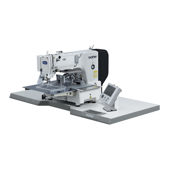
Brother BAS-311H Instruction Manual
Programmable electronic pattern sewer
Hide thumbs
Also See for BAS-311H:
- Service manual (162 pages) ,
- Instruction manual (42 pages) ,
- Basic operation manual (50 pages)

Related Manuals for Brother BAS-311H


Summary of Contents for Brother BAS-311H
- Page 1 BAS-311H INSTRUCTION MANUAL Please read this manual before using the machine. Please keep this manual within easy reach for quick reference. DIRECT DRIVE PROGRAMMABLE ELECTRONIC PATTERN SEWER...
- Page 2 Thank you very much for buying a BROTHER sewing machine. Before using your new machine, please read the safety instructions below and the explanations given in the instruction manual. With industrial sewing machines, it is normal to carry out work while positioned directly in front of moving parts such as the needle and thread take-up lever, and consequently there is always a danger of injury that can be caused by these parts.
-
Page 3: Safety Instructions
This symbol ( ) indicates something that you must do. The picture inside the circle indicates the ・・・・・・ nature of the thing that must be done. (For example, the symbol at left means “you must make the ground connection”.) BAS-311H... - Page 4 Furthermore, do not excessively bend the cords or secure them too firmly Contact your Brother dealer or a qualified electrician with staples, otherwise there is the danger that fire or for any electrical work that may need to be done.
-
Page 5: Maintenance And Inspection
Furthermore, do not apply excessive force when Ask your Brother dealer or a qualified electrician to tilting back the machine head. The sewing machine carry out any maintenance and inspection of the may become unbalanced and fall down, and serious electrical system. - Page 6 The following warning labels appear on the sewing machine. Please follow the instructions on the labels at all times when using the machine. If the labels have been removed or are difficult to read, please contact your nearest Brother dealer. *Safety devices...
- Page 7 Rear cover Tension release solenoid cover Inner cover L Outer cover Fixed cover Side cover Thread take-up cover Inner cover R Eye guard Outer cover Fixed cover Finger guard Gas spring support cover 3028B 3029B BAS-311H...
-
Page 8: Table Of Contents
7-4. Reading additional sewing data ......50 4-3. Winding the lower thread........24 4-4. Installing the bobbin case ......... 25 4-5. Thread tension..........26 4-5-1. Lower thread tension ......26 4-5-2. Upper thread tension ......26 4-6. Starting up ............27 BAS-311H... - Page 9 10-15. Adjusting the work clamp lift amount.... 66 10-16. Adjusting the air pressure (pneumatic work clamp specifications) ..66 10-17. If processing the work clamps and the feed plate to a shape that matches the sewing pattern ............67 BAS-311H...
-
Page 10: Names Of Major Parts
(11) Finger guard (3) Operation panel (12) Eye guard (4) Foot switch (13) Thread take-up cover (5) Work clamp switch (14) Rear cover (6) Start switch (7) STOP switch (8) Pulley (9) Cotton stand (10) Solenoid valve (pneumatic work clamp specifications) BAS-311H... -
Page 11: Specifications
Air pressure 0.5 MPa 1.8 l/min. (*1) The number of data items and stitches that can be stored will vary depending on the number of stitches in each program. (*2) No guarantees of operation can be given for any media. BAS-311H... -
Page 12: Installation
Furthermore, do not excessively bend the cords or secure them too firmly staples, Contact your Brother dealer or a qualified electrician otherwise there is the danger that fire or electric for any electrical work that may need to be done. -
Page 13: Table Processing Diagram
• The thickness of the table should be at least 40 mm, and it should be strong enough to bear the weight and vibration of the sewing machine. • Check that the control box is at least 10 mm away from the leg. If the control box and the leg are too close together, it may result in incorrect sewing machine operation. 3181B BAS-311H... -
Page 14: Installing The Control Box
(6) Spring washers [4 pcs.] (7) Nuts [8 pcs.] 3033B (8) Power switch (9) Wood screws [2 pcs.] (10) Staples [4 pcs.] Operator 1841B 3-3. Installing the oil pan (1) Oil pan (2) Nails [6 pcs.] (3) Waste oil tank 3034B BAS-311H... -
Page 15: Installing The Machine Head
Approx. 20 mm Approx. 20 mm 3035B (4) Hinge holders [2 pcs.] (5) Bolts [4 pcs.] (6) Plain washers [4 pcs.] (7) Nuts [4 pcs.] (8) Head rest (9) Bolts with washer [4 pcs.] 3036B BAS-311H... - Page 16 If the auxiliary plate (10) is lower than the needle plate, the feed plate may get caught on the needle plate. • Two or more people should tilt back the machine head, and it should be tilted gently while being held with both hands. 3037B BAS-311H...
- Page 17 (23) Plain washers (large) [2 pcs.] (24) Spring washers [2 pcs.] (25) Nuts [2 pcs.] (26) Gas spring shaft U (27) Retaining rings E [2 pcs.] 3038B (28) Gas spring support cover (29) Bolts with washer [6 pcs.] 3039B BAS-311H...
-
Page 18: Installing The Operation Panel
(2) Wood screws [4 pcs] * Pass the panel cord through the hole in the table, and then insert it into the control box through the hole in the side of the control box. (3) Staples [3 pcs] 3041B BAS-311H... -
Page 19: Installing The Two-Pedal Foot Switch
• Check that the connector is facing the correct way, and then insert it firmly until it locks into place. • Secure the cables with cable ties and cord clamps, while being careful not to pull on the connector. 3044B (Continued on next page.) BAS-311H... - Page 20 Home position sensor [12-pin] White P8 (SENSOR1) (2) (3) STOP switch [6-pin] White P9 (HEAD) (2) (3) NOTE: Route the X, Y and work clamp pulse motor harnesses so that they do not touch the power supply P.C. board. BAS-311H...
- Page 21 Close the cord presser plate (2) securely so that no foreign objects, insects or small animals can get inside the control box. 6. Check that the cords do not get pulled, and then gently return the machine head to its original position. 2291B BAS-311H...
-
Page 22: Connecting The Ground Wire
(3) Ground wires from two-pedal foot switch harnesses (2 wires) • Tighten the control box cover with the six screws. Check that the cords are not clamped by the cover at this time. NOTE: Make sure that the ground connections are secure in order to ensure safety. BAS-311H... -
Page 23: Connecting The Power Cord
• Take care when tapping in the staples (3) to make sure that they do not pierce the cords. • Do not use extension cords, otherwise machine operation problems result. Control box Green and yellow wire (ground wire) 2353B BAS-311H... - Page 24 • Do not use extension cords, otherwise machine operation problems result. 3. Use the six screws to tighten the cover of the control box. Check that none of the cords are being clamped by the cover at this time. Green and yellow wire (ground wire) BAS-311H...
- Page 25 3. Use the six screws to tighten the cover of the control box. Check that none of the cords are being clamped by the cover at this time. Green and yellow wire (ground wire) 3156B BAS-311H...
-
Page 26: Installing The Cotton Stand
3. INSTALLATION 3-10. Installing the cotton stand (1) Cotton stand NOTE: Fit the washer (2), and then securely tighten the nut (3) so that the cotton stand does not move. 3043B BAS-311H... -
Page 27: Installing The Pneumatic Unit (Pneumatic Work Clamp Specifications)
• When the lower knob is tightened, the lowering speed becomes slower. When it is loosened, the lowering speed becomes faster. You can operate the work clamp while the power is turned off by pressing the manual button. 3097B 1905B BAS-311H... -
Page 28: Installing The Eye Guard
3-13. Installing the side cover and rear cover (1) Side cover 3049B (2) Screws [4 pcs.] (3) Rear cover (4) Screws [4 pcs.] NOTE: Be careful not to clamp the cords when installing the side cover and the rear cover. 3050B BAS-311H... -
Page 29: Lubrication
Use only the lubricating oil <JX Nippon Oil & Energy Corporation Sewing Lube 10N; VG10> specified by Brother. * If this type of lubricating oil is difficult to obtain, the recommended oil to use is <Exxon Mobil Essotex SM10; VG10>. -
Page 30: Installing The Machine Head Fixing Bolt
<If error [E050], [E051] or [E055] is displayed> If the machine head switch (1) is not turned on, error [E050], [E051] or [E055] will occur. Use the screw (2) to adjust the installation position of the machine head switch as shown in the illustration. 3054B BAS-311H... -
Page 31: Preparation Before Sewing
• When threading the thread through the needle, allow a distance of approximately 40 mm between the needle hole and the end of the thread. If the trailing length of the thread is too long, it may cause the thread to become tangled. BAS-311H... -
Page 32: Threading Mode
THREAD/CLAMP indicator illuminates MENU indicator switches off 3061B 4427Q Threading the thread. Ending threading mode Press the THREAD/CLAMP key. • The work clamp will return to where it was before threading mode was started. 2390B THREAD/CLAMP indicator switches off BAS-311H... -
Page 33: Winding The Lower Thread
Loosen the set screw (7) and move the bobbin wider tension assembly (8) up and down to adjust. * For case A, move the bobbin winder tension assembly (8) down, and for case B, move it upward. Case A Case B 3065B BAS-311H... -
Page 34: Installing The Bobbin Case
4. Check that the bobbin turns in the direction of the arrow when the thread is pulled. 5. Pass the thread through the lever thread hole (4), and then pull out approximately 30 mm of thread. 6. Hold the latch on the bobbin case and insert the bobbin case into the rotary hook. BAS-311H... -
Page 35: Thread Tension
1. Turn the tension nut (1) (main tension) to adjust the tension as appropriate for the material being sewn. 2. Use the tension nut (2) (sub tension) to adjust the upper thread trailing length to about 40 mm. Stronger Weaker Stronger Weaker 3067B BAS-311H... -
Page 36: Starting Up
(If using a two-pedal foot switch, lower the work clamp before depressing the start switch (8).) 2nd step NOTE: If error "UP" appears when the foot switch is depressed, turn the pulley (1) in the direction of operation to clear the error. 3160B BAS-311H... -
Page 37: Using The Operation Panel (Basic Operations)
(10) SPEED indicator Illuminates when the SELECT key (14) is pressed to switch to the sewing speed setting. (11) COUNTER indicator Illuminates when the SELECT key (14) is pressed to switch to the lower thread or production counter setting. BAS-311H... - Page 38 (24) Setting keys [ Not used. (25) ENTER key Used to accept the values which are displayed in places such as the menu display (16). (26) Function keys [F1, F2, F3, F4] Used to directly select program numbers and cycle program numbers. BAS-311H...
-
Page 39: Program Setting Method
* When memory switch No. 100 is set to ON, slow start patterns can be recorded separately for each program number. * For details on memory switches, refer to “6-1. Setting memory switches”. BAS-311H... -
Page 40: Parameter List
* The setting can be displayed in “mm” units by setting memory switch No. 402 to “ON”. Y-scale 3074B 200 sti/min to 2800 sti/min Setting units are 100 sti/min. Initial value (Initial value is 2000 sti/min.) Sewing speed 3075B BAS-311H... - Page 41 *1 Sewing will be carried out at the sewing speed which is set by the parameters. Refer to “5-2-3. Using the production counter”. Counter Refer to “5-2-4. Split number setting method”. Split No. ON, OFF (Initial setting is “ON”.) Initial value Thread wiping 3158B BAS-311H...
-
Page 42: Using The Lower Thread Counter
If you press the RESET key (3) for 2 seconds or more, you can return the lower thread counter to its initial value even if the current value is not “0000”. 3079B BAS-311H... -
Page 43: Using The Production Counter
・ While pressing the ENTER key, press the F1 key. The production counter will be displayed as 7 digits while the keys are being pressed. ・ While pressing the ENTER key, press the F2 key. The lower thread counter will be displayed while the keys are being pressed. 3082B BAS-311H... -
Page 44: Split Number Setting Method
• Sewing is carried out each time in the order of steps 1 → 2 → 3 → 1 (for example, if there are two sections of split data). [Independent split] Memory switch No. 403 = 1 • The pattern for the displayed split number is sewn independently. BAS-311H... -
Page 45: Copying Programs
If a program has already been recorded in the selected copying destination program number, “..” will appear in the section display. For example, to copy to program number 201: 2382B 2383B 3085B Copy the program. Press the ENTER key. • The program items will be copied. 3086B 2414B BAS-311H... -
Page 46: Checking The Sewing Pattern
Once the test feed reaches the final stitch, the feed Press the TEST key. mechanism stops moving. 2404B TEST indicator switches off Depress the foot switch to the 1st step. 1st step The work clamp will rise and the preparation for sewing will be completed. 4441Q BAS-311H... -
Page 47: Setting The Work Clamp Lift Amount
• Press the ENTER key to accept the setting. 3090B NOTE: When setting the work clamp height and the intermediate presser foot work clamp height, check that the slider (1) is touching the work clamp lifter plate assembly (2). 3091B BAS-311H... - Page 48 * If it is set smaller, the intermittent presser When lowered foot will come into contact with the needle plate. Intermittent stroke Refer to “10-14. Changing the intermittent stroke” when making the adjustment. While sewing 5033Q BAS-311H...
-
Page 49: Using The Operation Panel (Advanced Operations)
Repeat steps 2 to 4 above to set each memory switch. Exit setting mode. Press the TEST key. ・ The changes will be memorized and the sewing machine will switch to home position detection standby. 2404B TEST indicator switches off BAS-311H... -
Page 50: List Of Memory Switch Settings
Parameters can be set separately for each program. Unit display for pattern zoom ratio Displayed as %. Displayed as mm. Split mode selection Continuous split mode Single split mode Cycle program No. (C01 to C30) display Disabled (not displayed) Enabled (displayed) BAS-311H... - Page 51 If memory switch No. 406 = 3, operation switches to the program number which C01 to C30 has been set. Assignment to F4 key 100 to 999, If memory switch No. 406 = 3, operation switches to the program number which C01 to C30 has been set. BAS-311H...
-
Page 52: Using Cycle Programs
・ The display will change from flashing to illuminated, and this means that the setting has been applied. ・ If you press the keys (4), the keys (5) or the TEST key without pressing the ENTER key, you can cancel the parameter changes. BAS-311H... - Page 53 (6). If you would like to continue setting another cycle program, repeat steps 2 to 5 above. End cycle program recording mode. Press the TEST key. This completes the recording of cycle programs. 2404B TEST indicator switches off BAS-311H...
- Page 54 (You do not need to carry out home position detection again.) 3106B 2382B 2383B * When memory switch No. 405 is set to OFF, the display of cycle programs can be turned off (skipped). BAS-311H...
-
Page 55: Direct Selection
Program No.C04 2443B 2444B 2445B 2442B 406=2 Item specified by memory Item specified by memory Item specified by memory Item specified by memory switch No. 407 switch No. 408 switch No. 409 switch No. 410 2444B 2445B 2442B 2443B BAS-311H... -
Page 56: Resetting All Settings To Their Defaults
* To clear individual programs, press the key to select the program number. 3108B 2382B 2383B Press the ENTER key for two seconds or more. • The menu display will change to illuminated and initialization will then be complete. 2414B Press the TEST key. 2404B BAS-311H... -
Page 57: Using Sd Cards
SD card, change the folder name. Memory switch Same as above ISMMSW.SEW Parameter Same as above ISMUPG.SEW Cycle program Same as above ISMCYC.SEW Error log \BROTHER\ISM\ISMLDT\ Stores the files which relate to error logs. BAS-311H... -
Page 58: Preparation For Reading And Writing Data
SD card. [LoG-] Error log data is written to the SD card. * The additional sewing data that can be used with this sewing machine is data which has been created for the BAS-311H or for the BAS-300G/311G. BAS-311H... -
Page 59: Reading Additional Sewing Data
・ If you would like to use any other read/write modes, press the key to select the mode and then run it. 3101B Ending read/write mode Press the TEST key. TEST indicator switches off 2404B * Contact the place of purchase for information on other reading and writing modes. BAS-311H... -
Page 60: Sewing
Use a work clamp which will hold the material securely so that it does not slip. If the material slips when using the standard work clamp and feed plate, process them so that the material does not slip. 3110B BAS-311H... -
Page 61: Using The Stop Switch
(The feed will move quicker if you keep the key pressed down.) 3113B Depress the foot switch to the 2nd step. (If using a two-pedal foot switch, depress the start switch.) 2nd step • The sewing machine will start operating and sewing will start. 4441Q BAS-311H... -
Page 62: Cleaning
(2) and the shuttle hook (3). 3115B 3. Clean all the dust and thread ends from around the driver (4), the top of the rotary hook thread guide and the shuttle race. 3116B BAS-311H... -
Page 63: Cleaning The Control Box Air Inlet Ports
3118B 9-5. Checking the needle Always check that the tip of the needle is not broken and also that the needle is not bent before starting sewing. 3119B 9-6. Lubrication Lubricate the sewing machine while referring to "3-14. Lubrication". BAS-311H... -
Page 64: Standard Adjustments
In addition, do not apply excessive force when tilting back the machine head. The sewing machine may Ask your Brother dealer or a qualified electrician to become unbalanced and fall down, and serious injury carry out any maintenance and inspection of the or damage to the sewing machine may result. -
Page 65: Thread Take-Up Spring
More thread Less thread (1) to the left. (The thread take-up amount will become greater.) * When sewing light material, move arm thread guide R (1) to the right. (The thread take-up amount will become less.) Index mark 3123B BAS-311H... -
Page 66: Adjusting The Needle Bar Height
If the driver (3) crosses the needle more than necessary, it will place a load on the needle, or it may cause poor thread tension. Furthermore, if it does not cross the needle at all, the tip of the rotary hook will interfere with the needle and skipped stitches may occur. BAS-311H... -
Page 67: Adjusting The Needle Clearance
• If the set screw (1) is turned clockwise, the lubrication amount becomes smaller. Less oil • If the set screw (1) is turned counterclockwise, the More oil lubrication amount becomes greater. Aligned 3127B BAS-311H... -
Page 68: Adjusting The Position Of The Movable Knife
6. Move the movable knife connecting plate (11) back and forth to adjust so that the distance from the ridge on the right side of the needle plate to the ridge on the movable knife (10) is 9.5 to 9.9 mm. 7. After tightening the bolt (9), check the above position once more. BAS-311H... - Page 69 12. Check that there is a gap of about 0 - 1 mm between the outside of the hole in the movable knife (10) and the ridge line on the shuttle race thread guide (14) when there is still play between the parts. BAS-311H...
-
Page 70: Replacing The Movable And Fixed Knives
* If the knife pressure is too strong and the movable knife (6) turns stiffly, use a thicker movable knife spacer. 7. Apply grease to the pin (12), place it into the movable knife connecting plate (13), and install it to the needle plate (5). 8. Check that the needle is aligned with the center of the needle hole. BAS-311H... -
Page 71: Installing The Feed Plate
Place the rear edge of the feed plate (1) against the stepped part of base plate Y (2) (shaded section (A)) and use a 2 mm diameter pin (such as a needle) to align the hole in the feed plate (1) with the hole in base plate Y (2); then tighten the two socket bolts (3). BAS-311H... -
Page 72: Adjusting The Thread Wiper
Install the presser foot (1) with the screw (2) so that the distance from the bottom of the presser foot to the top of the needle plate is 22 mm when the sewing machine is stopped and the presser foot (1) is raised. 5031Q BAS-311H... -
Page 73: Changing The Intermittent Stroke
If the position of the stepping clamp connecting rod is adjusted as described in the following at any one of the installation positions, the adjustment range for the intermittent stroke will as given in the following table. Installation position Intermittent stroke range 2 − 4.5mm 4.5 − 10mm 0 mm (Intermittent presser foot does not move up and down) 5012Q BAS-311H... - Page 74 <If they are touching> Remove the motor cover (4). Loosen the nut (5), and turn the bolt (6) until it is pressing against the intermittent drive lever (7), and then adjust until the two points mentioned above are not touching. BAS-311H...
-
Page 75: Adjusting The Work Clamp Lift Amount
If water has collected in the bottle of the regulator (1), turn the drain cock (3) in the direction indicated by an arrow to drain the water. NOTE: Open the air cock (4) slowly. 1912B BAS-311H... -
Page 76: If Processing The Work Clamps And The Feed Plate To A Shape That Matches The Sewing Pattern
Motor-driven work clamp specifications Pneumatic work clamp specifications The left and right work clamps are symmetrical. Center of sewing area [mm] <Feed plate processing diagram> Recommended thickness 1.5 mm Center of sewing area [mm] [mm] Center of sewing area 3159B BAS-311H... -
Page 77: List Of Error Codes
Check that connector P14 on the main P.C. board is properly connected. An operation panel key was still being pressed when the power was turned on, or key is faulty. E065 Turn off the power and check the operation panel. BAS-311H... - Page 78 Turn off the power, and then check the sewing machine motor. E150 (When sewing data with a small number of stitches (15 stitches or less) is sewn repeatedly (short cycle operation), the upper shaft motor may overheat and the “E150” error code may be generated.) BAS-311H...
- Page 79 Y-feed direction. Turn off the power, and then check that connectors P18 and P22 on the main E216 P.C. board are properly connected. Check that LD1 on the main P.C. board is illuminated while the power is on. (If it is not illuminated, fuse F2 is blown.) BAS-311H...
- Page 80 P19 and P23 on the main P.C. board are properly connected. Check that LD1 on the main P.C. board is illuminated while the power is on. (If it is not illuminated, fuse F2 is blown.) BAS-311H...
- Page 81 Turn off the power, and then check that connector P16 on the main P.C. board is properly connected. Internal memory is full and copying is not possible. E474 Press the RESET key to clear the error. Clear the sewing data. BAS-311H...
- Page 82 Turn off the power, and then check that connectors P4 and P20 on the main P.C. board are properly connected. Check that LD2 on the main P.C. board is illuminated while the power is on. (If it is not illuminated, fuse F1 is blown.) BAS-311H...
- Page 83 Version updating could not be carried out. Turn off the power, and then turn it back on again. E887 If an error code that is not listed above appears or if carrying out the specified remedy does not solve the problem, contact the place of purchase. BAS-311H...
-
Page 84: Troubleshooting
The thread wiper is obstructing the needle. Adjust the operating stroke of the Thread wiper does not P. 63 thread wiper. operate correctly. Adjust the operating stroke of the Thread wiper position is incorrect. P. 63 thread wiper. (Continued on next page) BAS-311H... - Page 85 * Recommended thickness: 1.5 mm Material is flapping. Process the work clamps and the feed plate into shapes that can hold the P. 67 material near the seam. Adjust the intermittent height of the P. 38 intermittent work clamp. (Continued on next page) BAS-311H...
- Page 86 Movable knife is not picking up the needle thread because the last stitch is Refer to "Skipped stitches occur". P. 76 being skipped. Lower thread is not cut. Lower thread tension is too weak. Increase the lower thread tension. P. 26 (Continued on next page) BAS-311H...
- Page 87 Fixed knife is blunt. P. 61 with a new one. Upper thread trailing length is irregular. Sub-tension is too weak. Adjust the sub-tension. P. 26 Thread take-up spring tension is too Increase the tension of the thread P. 56 weak. take-up spring. BAS-311H...
-
Page 88: Segment Display List
13. 7-SEGMENT DISPLAY LIST 13. 7-SEGMENT DISPLAY LIST 4268M BAS-311H... - Page 89 MEMO BAS-311H...
-
Page 90: Instruction Manual
INSTRUCTION MANUAL * Please note that the contents of this manual may differ slightly from the actual product purchased as a result of product improvements. © 2013 Brother Industries, Ltd. All Rights Reserved. BAS-311H SB4717-101 E This is the original instructions.