Cisco AP541N Quick Start Manual
Small business pro series dual-band single-radio access point
Hide thumbs
Also See for AP541N:
- Administration manual (172 pages) ,
- Quick start manual (17 pages) ,
- Brochure (2 pages)
Table of Contents
Advertisement
Quick Links
REVIEW DRAFT — CISCO CONFIDENTIAL
Cisco Small Business Pro
AP541N Dual-band Single-radio Access Point
Quick Start Guide
Package Contents
•
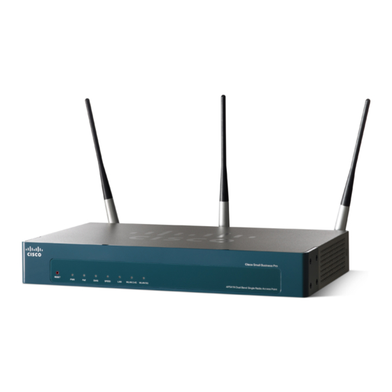
AP541N Dual-band Single-radio Access Point that includes an IEEE
802. 1 1a/b/g/n radio.
•
Three Antennas (These might be black or black-and-silver. This does not
affect performance.)
•
Screws and Wallboard Anchors
•
Grey Cat 5e Ethernet cable
•
Power supply
•
This quick start guide and companion notices
•
Product CD-ROM
Quick Start Guide
Advertisement
Table of Contents

Related Manuals for Cisco AP541N


Summary of Contents for Cisco AP541N
- Page 1 Cisco Small Business Pro AP541N Dual-band Single-radio Access Point Quick Start Guide Package Contents • AP541N Dual-band Single-radio Access Point that includes an IEEE 802. 1 1a/b/g/n radio. • Three Antennas (These might be black or black-and-silver. This does not affect performance.) •...
- Page 2 REVIEW DRAFT — CISCO CONFIDENTIAL Welcome Thank you for choosing the Cisco AP541N. The Cisco AP541N, part of the Cisco Smart Business Communications System (SBCS), is a wireless network communications device. This guide is designed to familiarize you with the general layout of the access point, how to deploy the device in your network, and access the configuration interface.
-
Page 3: Before You Begin
• PC with Microsoft Internet Explorer (version 6 and higher), Firefox (version 3 or higher), or Safari (for Mac). • TBD • TBD • Need Eng to provide the information for this section. Cisco AP541N Dual-band Single-radio Access Point Quick Start Guide... -
Page 4: Front Panel Leds
WLAN 2.4G—Lights solid green when a 2.4 GHz wireless network link is established. Blinks green when the link is passing traffic. The light is off when the 2.4 GHz radio is off. Cisco AP541N Dual-band Single-radio Access Point Quick Start Guide... -
Page 5: Back Panel Ports
We recommend using Cat5e or better cable. Also, do not exceed the maximum cabling distance of 328 feet (100 meters) per segment. ANT01, ANT02, and ANT03—BNC connectors that accept the antennas provided with the access point. Cisco AP541N Dual-band Single-radio Access Point Quick Start Guide... -
Page 6: Installing The Cisco Ap541N
Determine where you want to locate the access point. If you are using AC power, make sure the location is within reach of an AC power outlet. Keep enough ventilation space for the access point and check for any environmental restrictions. Cisco AP541N Dual-band Single-radio Access Point Quick Start Guide... -
Page 7: Wall Mounting
Before you begin, you need 2 wallboard screws (included) to mount the access point. We recommend using screws with a minimum of 4mm width at the head and a shaft diameter of at least 1.5mm. Cisco is not responsible for damages incurred by insecure wall- ARNING mounting. -
Page 8: Flat Surface Installation
To prepare the device for placement the device on a flat surface, do the following: Install the four rubber feet (included) on the bottom of the device. Place the access point on a desktop near an AC power source, unless you are using PoE. Cisco AP541N Dual-band Single-radio Access Point Quick Start Guide... -
Page 9: Connecting The Equipment
• Check the cable connections. • Check the LED states, as described in Getting to Know the Cisco AP541N, page If you need help resolving a problem, visit the Cisco Small Business Support Community at www.cisco.com/go/ smallbizsupport. For technical documentation and other links, see... -
Page 10: Getting Started With The Configuration
• dynamically assigned IP address allocated to the access point by a DHCP server. If you deploy the Cisco AP541N in a Cisco Small Business Pro network that is running DHCP, you can use Cisco Configuration Assistant 2.0 or higher to discover the Cisco AP541N IP address. -
Page 11: Display The Configuration Gui And Enable The Radio
GUI and enable the radio. Before you begin: • Verify that you have a power source for theCisco AP541N. If you will be deploying the Cisco AP541N by using PoE, it might be necessary to temporarily power the device by using the provided power supply or by connecting it to a hub or switch that provides PoE. - Page 12 REVIEW DRAFT — CISCO CONFIDENTIAL Enter the Cisco AP541N IP address in the address bar and press Enter. For example, enter http://192.168.10.10. The login window displays. Enter the default username cisco and the default password cisco. (Passwords are case sensitive.) The configuration window displays.
- Page 13 Possible Cause of Failure The most likely cause of connectivity failure is an incorrect IP address. DHCP is enabled on the Cisco AP541N by default. When a DHCP server is enabled on your network and the access point is connected to the network, the DHCP server replaces the default static IP address with a DHCP server–assigned IP address.
-
Page 14: Returning The Cisco Ap541N To The Factory Default Settings
• To restore the access point to the factory default settings: 1. Disconnect the access point from the network or disable all DHCP servers on your network. 2. With the power on, press-and-hold the Reset button for more than 10 seconds. Cisco AP541N Dual-band Single-radio Access Point Quick Start Guide... -
Page 15: Where To Go From Here
Search box. Product Documentation Cisco AP541N Access Point www.cisco.com/en/US/docs/wireless/ access_point/csbap/AP541N/quick_start/ guide/AP541N_QSG.pdf Cisco Small Business Cisco Partner Central for Small www.cisco.com/web/partners/sell/smb Business (Partner Login Required) Cisco Small Business Home www.cisco.com/smb Marketplace www.cisco.com/go/marketplace Cisco AP541N Dual-band Single-radio Access Point Quick Start Guide... - Page 16 Cisco, Cisco Systems, the Cisco logo, and the Cisco Systems logo are registered trademarks or trademarks of Cisco Systems, Inc. and/or its affiliates in the United States and certain other countries. All other trademarks mentioned in this document or Website are the property of their respective owners.
- Page 17 Federal Communication Commission Interference Statement This equipment has been tested and found to comply with the limits for a Class B digital device, pursuant to Part 15 of the FCC Rules. These limits are designed to provide reasonable protection against harmful interference when the equipment is operated in a commercial environment.
- Page 18 operate this equipment. For operation within 5.15 ~ 5.25GHz frequency range, it is restricted to indoor environment. This device complies with Part 15 of the FCC Rules. Operation is subject to the following two conditions: (1) This device may not cause harmful interference, and (2) this device must accept any interference received, including interference that may cause undesired operation.
- Page 19 Industry Canada statement This device complies with RSS-210 of the Industry Canada Rules. Operation is subject to the following two conditions: (1) This device may not cause harmful interference, and (2) this device must accept any interference received, including interference that may cause undesired operation.