
Related Manuals for Zell AC1000

Summary of Contents for Zell AC1000
- Page 1 ® Automobile Air-Con Service Solution AC1000 Operation Manual Haining Zell Automobile Testing and Inspection Equipments Co. , , , ,...
-
Page 2: Table Of Contents
............2 1.1 Zell hot-line of symbols in this operation manual . -
Page 3: About This Operation Manual
Keep this operation manual in the tool box of Air-Con Service Station, so that any information needed is always at your hand. 1.1 Zell hotline If you need more information about the Air-Con Service Station that is not concerned in this manual, call the Zell Hotline: 0086 0573 8783 1215... -
Page 4: Explanation Of Symbols In This Operation Manual
For illustrating the symbols in this operation manual Format Meaning Example Symbols used on the device Press „BOLD” Display messages „LANGUAGE” ■ ■ Text List in any order Pressure monitor ■ ■ Text Pressure relief valves 1. Text Actions to be carried out in the 1. -
Page 5: Scope Of Delivery
If any part is missing or damaged, notify the company responsible for transport immediately AC1000 Air-Con Service Station Blue hose with coupling for LP connection and red hose with HP connection Container for air conditioning compressor oil (PAG oil) -
Page 6: Safety
3 Safety 3.1 General safety instructions Read this operation manual carefully before starting up the Air-Con Service Station for the first time Please note the following: ■ the operator should comply with the laws about the service of vehicle air- conditioning by the local government. -
Page 7: Warnings On The Air-Con Service Station
→ Do not operate the Air-Con Service Station in areas where there is a risk of explosions (for example battery charging rooms or spraying booths). → Always use the main switch of the Air-Con Service Station for switching it on and off. Do not leave the device unattended when it is switch on. →... -
Page 8: Safety Devices
This Air-Con Service Station may only be used to service vehicle air-conditioning systems in which R134a refrigerant is used. Zell International assumes no liability for damage resulting from the following: Use for purposes more than those described in this operation manual. -
Page 9: Overview Of The Air-Con Service Station
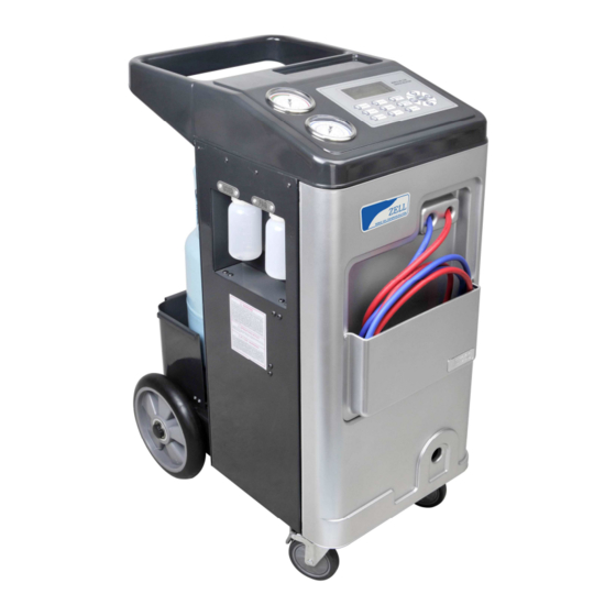
5 Overview of the Air-Con Service Station (10) (3) (4) (back) (5) (back) (7) (1) (8) (6) (2) (9) (11) (1)used oil bottle (2)new oil bottle (3)power switch(double fuses embedded) (4)pressure gauge for HIGH and LOW (6)HP and LP hoses (5)keypad (7)pressure gauge for working tank (8)working tank... - Page 10 USER COMMUNICATION INTERFACE: Recovery key : to recover the A/C refrigerant into the working tank Vacuum key : to extract gases from A/C system Purge key : to release non-condensable gases from working tank Recharge key : to refill refrigerant into A/C system. New oil key : to inject new oil into A/C system.
- Page 11 Pressure up key: to add gas to A/C system. Pressure down key: to remove gas from A/C system Vacuum test key: Vacuum test for detecting leakage Record print key: Record the previous 3 operations and to print recept (printer is an option item) Select keys: to shift the service items or edit the number inputted.
-
Page 12: First Start Up
6 First start-up 6.1 Setting up and switching on 220V or 110v Power supply must be firmly grounded 1. Drive the Air-Con Service Station to the workplace and lock the front wheels. Before operation the device must be on a level, flat surface so that measurement can be made correctly. -
Page 13: Putting Into The Bottles For New Oil
This means the weighting sy stem is out of work, need to be calibr ated. press and come to ZERO BALANCE item.More det ail inf orm ation, please ref er to 8. 3 6.2 Putting in the bottle for new oil Unscrew the PAG oil bottle, put about 150 ml new oil in and screw it back to the device. - Page 14 1. On standby mode, put the refill connector to the refrigerant bottle and fix it, then join the LP adapter with the low pressure hose(blue) to the connector, as Pic 4 Pic 4...
- Page 15 open the adapter, open the bottle valve and up side down it.press key, use the key to select the item you want (highlight field is activated), select “INTERNAL TANK REFILL” FUNCTION 1. INNER TANK REFILL 2. LANGUAGE SELECT 3. ZERO BALANCE 2.
-
Page 16: Operation
7 Operation When the automobile air-conditioning is serviced, the engine and the air-conditioning must be switched off. 7.1 Recovery Recovery operation is the process that the Air-Con Service Station sucks the refrigerant from the vehicle A/C system, purity it and storage the gas into the working tank. -
Page 17: Vacuum
4. After about 5 seconds , The oil draining process would be finished. RECOVERY FINISHED! PRESS OK TO CONFIRM! 5. Press key to stop the alarm buzzer, then the recovery process finished! Note: After first phase of recovery, you need to spend some minutes, just waiting for more refrigerant evaporate into gas, if the pressure inside the A/C raised, the equipment will go on the recovery process, or it will go to next step. -
Page 18: Purge
2. Use to set the vacuum time (suggest at least10 minutes). 3. Press , the device will start vacuum operation. VAC UU M RU NN IN G ** : ** Pr es s ESC to qui t! 4.The device will be finished automatically after expiry of the vacuum time, press return to the standby mode. -
Page 19: Oil Injection
OIL INJECTION INJECTION PRESS OK TO START 2. Use to adjust the oil quantity, then press OK, it will finish automatically. Or long press key, the new PAG oil would be sucked into the A/C system. Watch the scale of the PAG bottle, when the oil is added with the desired quantity, stopped the operation. -
Page 20: Recharge
2. Press key to adjust the refrigerant filling quantity. You could check the amount on the vehicle, or press key to use the database embedded. 3. When all are ready, press to start, it will recharge the air-conditioning with the refrigerant. RE CH AR G E RU NN IN G **: * *... - Page 21 7.5 Purge The purge is designed to discharge the mixed non-condensable gases in the inner tank. It is harmful for the A/C station when the tank pressure is exceeded. It must release some pressure till to normal level. You no need to do this operation every time when you service a car, but need to check the tank pressure through the gauge in the morning before using it.
-
Page 22: Auto
7.6 AUTO The automatic operation is including recovery, oil drain, vacuum, oil injection, and recharging, all steps are in one press. Before operation, you must confirm that the new PAG oil is enough, or it has risk that the air would be sucked into the vehicle A/C system. -
Page 23: Pressure Up
7.7 PRESSURE UP When the A/C system pressure is lower than desired, only due to shortage of refrigerant inside the A/C system, In this case, you no need redo all recovery/recycling/recharging process, by this function you could add some gas into the system and let the pressure rise to normal. -
Page 24: Vacuum Test
7.9 VACUUM TEST After a vacuum operation,if the A/C system can hold the vacuum state, that means the system is OK, if it lost some vacuum, there should be existing the leakage in somewhere. the operation is divided into two steps, first is vacuum, second is vacuum test. -
Page 25: Record Print
When test finished , if OK,the LCD show VACUUM TEST VACUUM FINISHED 10:00 TEST OK Press OK to CONFIRM If not OK, VACUUM TEST VACUUM FINISHED 10:00 TEST FAILED Press OK to CONFIRM 4. Press key, to exit the program. 7.10 RECORD PRINT It can show 3 records in all for the previous operation. -
Page 26: Service Tasks
8 Service tasks Other service are included this items as: “1.INNER TANK REFILL 2.LANGUAGE SELECT 3.ZERO BALANCE 4.VACUUM PUMP OIL 5.FILTER DRIVER 6.HOSE COMPENSATION 7.PRESSURE RISE WAIT 8.OTHER SERVICE.” If you want come to these items , please press key and use to select and enter it. -
Page 27: Vacuum Pump Oil
1. In standby mode, press key ,to use the key to select “ZERO BALANCE” item ZERO BALANCE PRESS OK WHEN PREPARED! 2. Remove the fix screw and lift the tank off from the scale plate. Make sure that there is NOTHING on, press key . -
Page 28: Changing The Internal Filter
1. Open the front cover by unfix the screw 1 and 2 . Place a vessel with capacity of at least 1/2 litre under the Air-Con Service Station. The used oil in the vacuum pump would flow through the outlet in the base of the device. - Page 29 1. Take off the front panel, Remove the filter cartridge on the left side and replace it with a new one. When inserting a new filter cartridge, observe the flow direction (FLOW arrow must point downwards). 2. conform that the new filter drier is well fixed. 3.
-
Page 30: Hose Compensation
8.6 Hose compensation You can service yourself by inputting a new quantity of refrigerant as a compensation when the recharging occurs. note: we strongly claim to use the default setting of compensation 8.7 Pressure rise wait Setting the waiting time that the refrigerant evaporate in the A/C system , during the recovery operation phase.the more minutes you set,the more percent of gas could be recovered. -
Page 31: Disposal
9. Disposal 9.1 Disposing of used fluids Used oil is hazardous waste. Do not mix used oil with other fluids. Keep used oil in suitable containers prior to disposal. 9.2 Disposing of packaging material ■ The cardboard packaging material should be disposed of with other waste paper. -
Page 32: Trouble Shooting
10 Trouble shooting Fault Cause Remedy The display shows This message is normal, during the „WARNING! Press continue CODE :W16 recovery process. NOT ENOUGH PRESSURE other operations. If you TO RECOVERY!.” make sure that there is no refrigerant in A/C system . The display shows The inner tank is full of Drain the internal... -
Page 33: Technical Data
11 Technical data Dimensions (width x height x depth) 600 mm x 1150 mm x 700 mm Weight 80 kg Power supply 220 V- 50 Hz Refrigerant R134a Vacuum pump 1L / min Compressor 3/8 P Filling cylinder accumulator capacity 80 kg LCD back-lit display 192*64...