Table of Contents
Advertisement
Available languages
Available languages
Quick Links
Advertisement
Table of Contents

Related Manuals for Philips MANT950


Summary of Contents for Philips MANT950
- Page 1 E E N N User manual S S P P Manual De Utilizador MANT950...
- Page 2 Contents S S a a f f e e t t y y I I n n s s t t r r u u c c t t i i o o n n s s I I n n c c l l u u d d e e d d w w i i t t h h A A n n t t e e n n n n a a M M o o u u n n t t i i n n g g A A n n t t e e n n n n a a C C o o n n n n e e c c t t i i n n g g t t o o y y o o u u r r T T V V W a a r r r r a a n n t t y y...
- Page 3 Safety Instructions ANTENNA LEAD-IN WIRE GROUND CLAMP TO ROTATOR CONTROL UNIT TO EXTERNAL ANTENNA TERMINALS OF PRODUCT ELECTRIC SERVICE POWER SERVICE GROUND- EQUIPMENT ING ELECTRODE SYSTEM (NEC ART 250, PART H) GROUND CLAMPS National Electrical Code NEC - * Antenna Discharge Unit is not required if lead in conductors are enclosed in a continuous metallic shield that is permanently and effectively grounded.
- Page 4 Do not install antenna wire(s) over or under utility lines. Important installation information The MANT950 uses a power injector that sends a low power DC voltage to the antenna to drive the signal amplifier built into the antenna though the RG-6 or RG-59 signal cable.
-
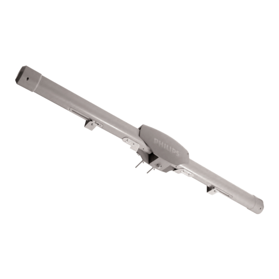
Page 5: Parts Included
Included with Antenna Mounting Antenna Fig A Parts included: 1. MANT950 Antenna 2. 12VDC, 200mA Power Injector 3. Main Bracket 4. 1/2" screws & washers) 5. U-Bolts 6. Mast clamps 7. Wing-nuts 7. L-Bracket 8. 2" Wood Screws 9. 20' RG-59U cable with connectors 10. - Page 6 Mounting Antenna Fig B Fig C Connecting to your TV screws into the wall but leave about 1/2” to allow for the last step. 4. Attach the cable to the F connector on the underside of the unit and slide the weather protection boot over the connection. 5.
-
Page 7: Limited Lifetime Warranty
Connecting to your TV S S a a f f e e t t y y N N o o t t e e - - T T h h e e p p o o w w e e r r i i n n j j e e c c t t o o r r a a n n d d p p o o w w e e r r s s u u p p p p l l y y i i s s f f o o r r i i n n d d o o o o r r u u s s e e o o n n l l y y ! ! Alternate connections 1. -
Page 8: Technical Support
Technical Support Technical Support For Technical support send an email with the model number of the product and a detailed description of your problem to: Email: tech.support@philips.com ©2005 Accessories Service Center Philips Accessories and Computer Peripherals, Ledgewood, NJ 07852 USA... -
Page 9: Table Of Contents
Contenido Instrucciones de seguridad Partes incluidas: Montaje de la antena Conexión de su TV Garantía limitada por vida Asistencia Técnica:... -
Page 10: Instrucciones De Seguridad
Instrucciones de seguridad Grapa de puesta a tierra A la unidad de control del rotator A terminales de antena externos del producto Equipo de servicio eléctrico NEC - National Electrical Code * Antenna Discharge Unit is not required if lead in conductors are enclosed in a contin- uous metallic shield that is permanently and effectively grounded. - Page 11 Información importante sobre la instalación MANT950 usa un inyector de energía que envía bajo voltaje de cor- riente directa a la antena para impulsar el amplificador de señal inte- grado en la antena mediante el cable de señal RG-6 o RG-59.
-
Page 12: Partes Incluidas
El no cumplimiento de este aviso puede causar daños al inyector de energía o funcionamiento inadecuado bajo rendimiento. Partes incluidas: 1. Antena MANT950 2. Inyector de energía de 12V y 200mA para corriente directa 1 3. Soporte principal 4. Tornillos y arandelas de ?”... - Page 13 Montaje de la antena Fig A Fig B Realice todo el trabajo de ensamblaje de la antena en el suelo. Levante la antena completa luego del ensamblaje. 1. Una el soporte principal al ensamblaje de la antena mediante los tornillos y las arandelas 6-1/8”, tal como se muestra arriba en la Figura A 2.
-
Page 14: Conexión De Su Tv
Montaje de la antena Fig C Conexión de su TV Amplificador 4. Coloque las 4 tuercas mariposa en la rosca de los pernos en forma de U y deje espacio suficiente para la torre. 5. Deslice el extremo superior de la torre debajo de los pernos y ajuste bien las tuercas mariposa. -
Page 15: Garantía Limitada Por Vida
Esta garantía le otorga derechos legales específicos, y usted puede tener otros derechos que pueden variar de estado a estado. Asistencia Técnica: Correo electrónico: tech.support@Philips.com ©2005 Centro de Servicio de Accesorios Philips Accessories and Computer Peripherals, Ledgewood, NJ 07852 USA Calidad comprobada en los EE.UU. - Page 16 Specifications are subject to change without notice Trademarks are property of Philips Accessories and Computer Peripherals 2005© Philips Accessories and Computer Peripherals, Ledgewood, NJ USA www.philips.com 000 000 00000...