Table of Contents
Advertisement
Quick Links
Advertisement
Table of Contents

Related Manuals for Cisco IPV5000


Summary of Contents for Cisco IPV5000
- Page 1 Installation Guide Cisco IPV50xy/IPV60xy High-Defi nition IP Set-Tops...
-
Page 3: Table Of Contents
Serial Number ........................7 In This Guide .........................7 Open Source License Statement ..................7 IPV5000, IPV5001, IPV6003, IPV6005, and IPV6006 Front Panel ........8 IPV5000, IPV5001, IPV6003, IPV6005, and IPV6006 Back Panel........9 IPV5010, IPV5050, IPV6013, IPV6015 and IPV6016 Front Panel ........10 IPV5010, IPV5050, IPV6013, IPV6015 and IPV6016 Back Panel ........11 Connecting the Set-Top .....................12... -
Page 4: Notice For Installers
Notice for Installers The servicing instructions in this notice are for use by qualifi ed service personnel only. To reduce the risk of electric shock, do not perform any servicing other than that contained in the operating instructions, unless you are qualifi ed to do so. Note to System Installer For this apparatus, the cable shield/screen shall be grounded (earthed) as close as practical to the point of entry of the cable into the building. - Page 5 IMPORTANT SAFETY INSTRUCTIONS, continued Handling Disposable Batteries Protect from Exposure to Moisture This product may contain disposable batteries. Heed the following and Foreign Objects warning and follow the Battery Safety and Battery Disposal instructions below. WARNING: Avoid electric shock and fi re hazard! Do not expose this product to dripping or splashing liquids, WARNING: There is danger of explosion if the battery rain, or moisture.
-
Page 6: Change The Way You Watch Tv
MPEG2 and H.264 decoding. Supports 480i, 576i, 720p, 1080i and 1080p content. Uses Ethernet over CAT-5 • IPV5001 set-top—The IPV5001 is the same as the IPV5000 but has 16 GB of eMMC fl ash memory • IPV5010 set-top—The IPV5010 is the same as the IPV5000 but also uses HPNA v3 in-home networking over coaxial cable •... -
Page 7: Safety First
Cisco Systems, Inc. Open Source License Statement Cisco IPV5K and IPV6K Series set-tops may contain, in part, certain free and/or open source software (“Open Source”) under separate license terms. Examples of such licenses may include all versions of the GNU General Public License (GPL), GNU Lesser General Public License (LGPL), BSD license, MIT license, Mozilla Public License, Eclipse Public License, Apache license, and others. -
Page 8: Ipv5000, Ipv5001, Ipv6003, Ipv6005, And Ipv6006 Front Panel
IPV5000, IPV5001, IPV6003, IPV6005, and IPV6006 Front Panel 1 Power Turns the set-top on or places it in standby 2 Power LED Indicates that the set-top is powered on. The LED is white 3 SIG LED Indicates network link status. The LED is green 4 HD LED Indicates that the set-top is set to a resolution of 720p, 1080i, or 1080p. -
Page 9: Ipv5000, Ipv5001, Ipv6003, Ipv6005, And Ipv6006 Back Panel
IPV5000, IPV5001, IPV6003, IPV6005, and IPV6006 Back Panel 12V DC S/PDIF SCART HDMI ETHERNET Reset 1 S/PDIF Connect to an optical cable to send a digital audio signal to a surround sound system or other digital audio device 2 SCART... -
Page 10: Ipv5010, Ipv5050, Ipv6013, Ipv6015 And Ipv6016 Front Panel
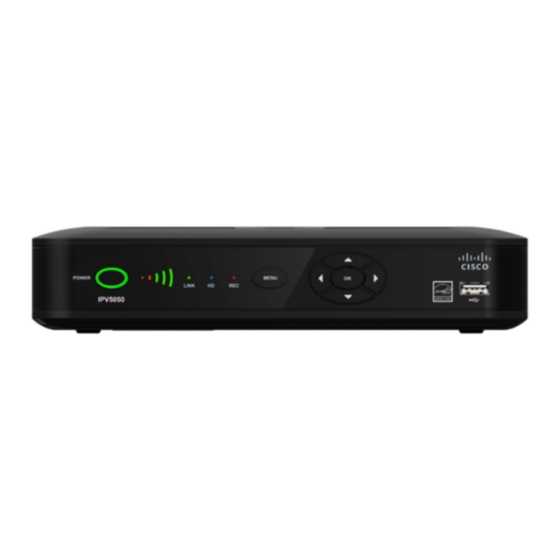
IPV5010, IPV5050, IPV6013, IPV6015, and IPV6016 Front Panel POWER MENU LINK 4 5 6 1 Power Turns the set-top on or places it in standby 2 LED halo LED is green for power on, red for standby 3 Signal Strength Identifi es the strength of the wireless connection (Optional) Indicator 4 LINK... -
Page 11: Ipv5010, Ipv5050, Ipv6013, Ipv6015 And Ipv6016 Back Panel
IPV5010, IPV5050, IPV6013, IPV6015, and IPV6016 Back Panel CVBS HDMI NETWORK OPTICAL POWER F-Con 1 F-Con Connect to in-house coaxial wiring, if applicable (Optional) 2 Pr Pb Y Connect the receiver to the component video input (PrPbY) on the HDTV. See pages 14 and 15 for more information 3 CVBS... -
Page 12: Connecting The Set-Top
Connecting the Set-Top To connect your set-top to your network and home entertainment devices, complete these steps: Because the connections for a high-defi nition (HD) or standard-defi nition (SD) TV are diff erent, you must determine if your TV is HD or SD. -
Page 13: Connecting To The In-Home Network
Connecting to the In-Home Network The following diagrams illustrate examples of the connections that you can use to connect your set-top to your in-home network. Contact your service provider for the recommended connection method for your home. (This section does not apply to the IPV5050; see Connection for IPV5050 Wireless Set-Top on page 16.) -
Page 14: Connections For A High-Defi Nition Tv (Hdtv)
Connections for a High-Defi nition TV (HDTV) To use the set-top with an HDTV, you must make one of the following connections to view the HD content. See the owner’s manual for your TV and the cabling diagrams in this guide for more detailed connection information. -
Page 15: Connections For A Standard-Defi Nition Tv (Sdtv)
Connections for a Standard-Defi nition TV (SDTV) When using the set-top with an SDTV, you must make one of the following connections to view content. Some SDTVs may not have all of these connections. See the owner’s manual for your TV and the cabling diagrams in this guide for more detailed information. -
Page 16: Connections For An Over-The-Air Converter Box
Connections for an Over-the-Air Converter Box You can connect an over-the-air converter box directly to your TV to receive certain local channels, but do not connect the over-the-air converter box directly to your set-top. Connection for IPV5050 Wireless Set-Top The IPV5050 set-top allows for easy and secure establishment of a wireless home network. The signal strength indicator on the front panel of the set-top allows you to identify the strength of your wireless connection. -
Page 17: Connecting To An Hdtv With An Hdmi Connector
Connecting to an HDTV with an HDMI Connector Cable Used in this Confi guration • 1 HDMI Cable Notes: • The HDMI port on the TV must support high-bandwidth digital content protection (HDCP) • The HDMI interface supports Dolby Digital 5.1 audio WARNING: Electric shock hazard! Unplug all electronic devices before connecting or disconnecting any device cables to the set-top. -
Page 18: Connecting To An Hdtv With A Dvi Connector
Connecting to an HDTV with a DVI Connector Cables Used in this Confi guration • 1 HDMI-to-DVI Cable or 1 HDMI Cable and 1 HDMI-to-DVI Adapter • 1 Audio Left/Right Cable (You can also use an optical cable [indicated by the dotted line] instead of the Audio Left/Right Cable as shown in the diagram, dependent upon your TV’s capabilities.) Notes: •... -
Page 19: Connecting To An Hdtv With Component (Ypbpr) Connectors
Connecting to an HDTV with Component (YPbPr) Connectors Cables Used in this Confi guration • 1 Component Video Cable (YPbPr) • 1 Audio Left/Right Cable (You can also use an optical cable [indicated by the dotted line] instead of the Audio Left/Right Cable as shown in the diagram, dependent upon your TV’s capabilities.) WARNING: Electric shock hazard! Unplug all electronic devices before connecting or disconnecting any device cables to the set-top. -
Page 20: Connecting To An Sdtv With Component (Ypbpr) Connectors
Connecting to an SDTV with Component (YPbPr) Connectors Cables Used in this Confi guration • 1 Component Video Cable (YPbPr) • 1 Audio Left/Right Cable Note: The set-top must be set to the proper standard-defi nition mode. WARNING: Electric shock hazard! Unplug all electronic devices before connecting or disconnecting any device cables to the set-top. -
Page 21: Connecting To An Sdtv With An Rca-Type Connector
Connecting to an SDTV with an RCA-Type Connector Cables Used in this Confi guration • 1 RCA-type Video Cable • 1 Audio Left/Right Cable WARNING: Electric shock hazard! Unplug all electronic devices before connecting or disconnecting any device cables to the set-top. Back of Set-Top F-Con CVBS... -
Page 22: Connecting To An Sdtv With A Scart Connector
Connecting to an SDTV with a SCART Connector Cables Used in this Confi guration • MiniDin to SCART Adapter Cable WARNING: Electric shock hazard! Unplug all electronic devices before connecting or disconnecting any device cables to the set-top. Back of Set-Top 12V DC S/PDIF SCART... -
Page 23: Troubleshooting
Troubleshooting If the set-top does not perform as expected, the following tips may help. If you need further assistance, contact your service provider. No Picture • Verify that the power to your TV is turned on • If the set-top is plugged into a wall switch, verify that the switch is in the ON position •... -
Page 24: Frequently Asked Questions
Frequently Asked Questions What Is Digital Television? Digital television (DTV) is a huge leap forward in television technology compared to analog television that has been widely available since the 1940s. DTV is delivered and displayed using digital encoding, similar to the way a PC operates. By using digital technology, there is no variation in picture and sound quality from the origination point until it is displayed on your television. -
Page 25: Picture Formats
Picture Formats What Is the Diff erence Between a Standard-Screen and a Wide- Screen HDTV? The type of screen your HDTV has (wide-screen or standard-screen) determines how the set-top displays programs on the screen. The picture format for an HDTV is a combination of aspect ratio and screen resolution and is diff erent for standard-screen and wide-screen HDTVs. -
Page 26: Compliance Information
Any changes or modifi cations not expressly approved AVC VIDEO LICENSE by Cisco Systems, Inc., could void the user’s authority With respect to each AVC/H.264 product, we are to operate the equipment. obligated to provide the following notice: This device is restricted to indoor use only. - Page 27 IC (Industry Canada) Notice RF Exposure Statements Notice: The Industry Canada (formerly Canadian Note: This transmitter must not be co-located or Department of Communications) label identifi es certifi ed operated in conjunction with any other antenna or equipment. This certifi cation means that the equipment transmitter.
- Page 28 20110311 CE_Gateway Richtlijn 1999/5/EC. Cisco and the Cisco logo are trademarks or registered trademarks of Cisco and/or its affi liates in the U.S. and other countries. To view a list of Cisco trademarks, go to this URL: www.cisco.com/go/trademarks. Third-party trademarks mentioned are the property of their respective owners.