Sony XM-1252GTR Service Manual
Hide thumbs
Also See for XM-1252GTR:
- Operating instructions manual (20 pages) ,
- Specification sheet (2 pages) ,
- Operating instructions (2 pages)
Table of Contents
Advertisement
SERVICE MANUAL
Ver. 1.0 2005. 12
AUDIO POWER SPECIFICATIONS (US MODEL)
POWER OUTPUT AND TOTAL HARMONIC DISTORTION
125 watts per channel minimum continuous average power into
4 ohms, both channels driven from 20 Hz to 20 kHz with no more
than 0.1% total harmonic distortion per Car Audio Ad Hoc
Committee standards.
Other Specifications
Circuit system
OTL (output transformerless) circuit
Pulse power supply
Inputs
RCA pin jacks
High level input connector
Outputs
Speaker terminals
Suitable speaker impedance
2 – 8 Ω (stereo)
4 – 8 Ω (when used as a bridging amplifier)
Maximum outputs
280 W × 2 (at 4 Ω)
400 W × 2 (at 2 Ω)
800 W (monaural) at 4 Ω
Rated outputs (supply voltage at 14.4 V)
125 W × 2 (20 Hz – 20 kHz, 0.1% THD,
at 4 Ω)
170 W × 2 (20 Hz – 20 kHz, 0.15% THD,
at 2 Ω)
340 W (monaural) (20 Hz – 20 kHz, 0.15% THD,
at 4 Ω)
Frequency response
5 Hz – 50 kHz (
Input level adjustment range
0.3 – 6.0 V (RCA pin jacks)
1.2 – 12.0 V (High level input)
Sony Corporation
9-879-998-01
2005L04-1
eVehicle Division
© 2005. 12
Published by Sony Engineering Corporation
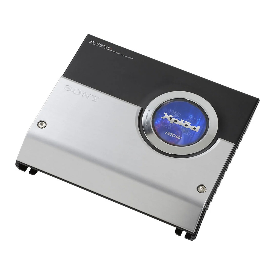
XM-1252GTR
SPECIFICATIONS
+0
dB)
–3
Low-pass filter
80 Hz, –12 dB/oct
High-pass filter
80 Hz, –12 dB/oct
Low boost
0 – 10 dB (40 Hz)
Power requirements
12 V DC car battery
(negative ground)
Power supply voltage
10.5 – 16 V
Current drain
at rated output : 32 A (at 4 Ω)
Remote input : 1 mA
Dimensions
Approx. 322 × 55 × 275 mm
(12
× 2
× 10
3/4
1/4
(w/h/d) not incl. projecting parts and controls
Mass
Approx. 4.4 kg (9 lb. 12 oz.) not incl. accessories
Supplied accessories
Mounting screws (4)
High level input cord (1)
Design and specifications are subject to change without
notice.
STEREO POWER AMPLIFIER
US Model
Canadian Model
E Model
in.)
7/8
1
Advertisement
Table of Contents

Related Manuals for Sony XM-1252GTR


Summary of Contents for Sony XM-1252GTR
-
Page 1: Service Manual
5 Hz – 50 kHz ( –3 Input level adjustment range 0.3 – 6.0 V (RCA pin jacks) 1.2 – 12.0 V (High level input) STEREO POWER AMPLIFIER Sony Corporation 9-879-998-01 2005L04-1 eVehicle Division © 2005. 12 Published by Sony Engineering Corporation... -
Page 2: Table Of Contents
LES COMPOSANTS IDENTIFIÉS PAR UNE MARQUE 0 SUR LES DIAGRAMMES SCHÉMATIQUES ET LA LISTE DES PIÈCES SONT CRITIQUES POUR LA SÉCURITÉ DE FONCTIONNEMENT. NE REMPLACER CES COMPOSANTS QUE PAR DES PIÈCES SONY DONT LES NUMÉROS SONT DONNÉS DANS CE MANUEL OU DANS LES SUPPLÉMENTS PUBLIÉS PAR SONY. -
Page 3: General
XM-1252GTR SECTION 1 GENERAL This section is extracted from instruction manual. Features Caractéristiques Low boost Amplification de basses fréquences • Maximum power output of 280 W per channel • Puissance de sortie maximale de 280 W par canal (at 4 Ω). -
Page 4: Connections
XM-1252GTR Connections Connexions 2-Speaker System Système à 2 haut-parleurs Caution Attention For details on the settings of switches and Car audio unit controls, refer to “Location and Function of • Before making any connections, disconnect • Avant d’effectuer les connexions, débranchez Autoradio Controls.”... - Page 5 XM-1252GTR Dual Mode System (With a Bridged Subwoofer) 2-way System Double mode de connexion (avec un haut-parleur Système 2 voies d’extrêmes graves en pont) Two output channels Deux canaux de sortie Car audio unit Autoradio LINE OUT LP OFF FILTER(80Hz)
- Page 6 XM-1252GTR High Level Input Connection (2-Speaker System) Connexion d’entrée à haut niveau (Système à 2 haut-parleurs) Left speaker output White Sortie haut-parleur gauche Blanc Black-striped cord Car audio unit Cordon rayé noir Autoradio Gray Right speaker output Gris Sortie haut-parleur droit Black-striped cord Cordon rayé...
-
Page 7: Disassembly
XM-1252GTR SECTION 2 DISASSEMBLY Note : This set can be disassemble according to the following sequence. 2-1. COVER ASSY (Page 7) 2-2. TOP PLATE SECTION (Page 8) 2-5. LED ILLUM BOARD, 2-3. AMP BOARD SECTION LED PROT BOARD (Page 8) (Page 9) 2-4. - Page 8 XM-1252GTR 2-2. TOP PLATE SECTION 2 four screws (+BTP 3 × 8) 3 two screws (+BTP 3 × 8) 1 screw 6 top plate section (+BVST 3 × 6) 5 CN810 2-3. AMP BOARD SECTION 2 two screws (+BTP 3 × 8) 3 three screws (+BTP 3 ×...
-
Page 9: Front Panel
XM-1252GTR 2-4. FRONT PANEL 2 two screws (+BTP 3 × 8) 1 two screws (+BTP 3 × 8) AMP board 3 front panel 2-5. LED ILLUM BOARD, LED PROT BOARD 1 screw (+BTP 2.6 × 5) 2 LED ILLUM board 3 screw (+BTP 2.6 ×... -
Page 10: Electrical Adjustment
XM-1252GTR SECTION 3 ELECTRICAL ADJUSTMENT Bias Adjustment Note : In Bias Adjustment, adjust RV103 if any of Q108 through Q111 are replaced. Adjust RV203 if any of Q208 through Q211 are replaced. Condition : This adjustment should be performed about one minute after the remote mode is turned on at a room tempera- ture of about 25°C. -
Page 11: Diagrams
XM-1252GTR SECTION 4 DIAGRAMS • Semiconductor Location (AMP BOARD) THIS NOTE IS COMMON FOR PRINTED WIRING BOARDS Ref. No. Location Ref. No. Location AND SCHEMATIC DIAGRAMS. (In addition to this, the necessary note is D-13 IC303 printed in each block.) -
Page 12: Printed Wiring Boards
XM-1252GTR 4-1. PRINTED WIRING BOARDS • Refer to page 11 for Semiconductor Location. : Uses unleaded solder. TP63 JW213 JW19 R823 R245 R243 JW212 Q210 Q208 TH803 R246 Q211 Q804 JW214 JW215 R244 TP25 Q207 R833 Q803 JW216 Q209 C227... -
Page 13: Schematic Diagram –Amp Section (1/2)
XM-1252GTR 4-2. SCHEMATIC DIAGRAM — AMP SECTION (1/2) — • Refer to page 11 for IC Block Diagram and Waveform. CN803 C107 R107 S802 R105 C113 C104 C111 C108 R106 C112 R104 R301 IC102(1/2) C101 IC302(1/2) R101 C109 C303 C301... -
Page 14: Schematic Diagram -Amp Section (1/2)
XM-1252GTR 4-3. SCHEMATIC DIAGRAM — AMP SECTION (2/2) — R135 C124 R801 C801 R145 R131 R155 Q110 Q801 Q105 R800 IC301(2/2) Q103 Q102 R120 Q108 D801 RV103 R143 D108 R802 R160 Q114 C127 R139 C123 D106 R149(2/2) R149(1/2) D104 R141... -
Page 15: Exploded Views
XM-1252GTR SECTION 5 EXPLODED VIEWS NOTE: • The mechanical parts with no reference • Color Indication of Appearance Parts The components identified by mark 0 or dotted line with mark number in the exploded views are not supplied. Example : 0 are critical for safety. -
Page 16: Amp Board Section
XM-1252GTR 5-2. AMP BOARD SECTION Q211, Q208 not supplied Q209, Q210 Q109, Q110 not supplied Q904, Q909 Q111, Q108 D905, D906 not supplied Q906, Q907 Ref. No. Part No. Description Remark Ref. No. Part No. Description Remark 2-661-801-01 PANEL, FRONT... -
Page 17: Electrical Parts List
XM-1252GTR SECTION 6 ELECTRICAL PARTS LIST NOTE: • Due to standardization, replacements in • Items marked “*” are not stocked since The components identified by mark 0 or dotted line with mark the parts list may be different from the they are seldom required for routine service. - Page 18 XM-1252GTR Ref. No. Part No. Description Remark Ref. No. Part No. Description Remark C914 1-162-964-11 CERAMIC CHIP 0.001uF D803 8-719-988-61 DIODE 1SS355TE-17 C915 1-137-194-81 FILM 0.47uF D820 8-719-988-61 DIODE 1SS355TE-17 C916 1-137-372-11 MYLAR 0.022uF D822 8-719-988-61 DIODE 1SS355TE-17 C917 1-131-731-12 ELECT...
- Page 19 XM-1252GTR Ref. No. Part No. Description Remark Ref. No. Part No. Description Remark Q109 X-3381-587-1 FET PAIR ASSY (P) (IRF9540) (set of 2) R129 1-216-841-11 METAL CHIP 1/10W Q110 X-3381-586-1 FET PAIR ASSY (N) (IRF540) (set of 2) R130 1-216-829-11 METAL CHIP 4.7K...
- Page 20 XM-1252GTR LED ILLUM Ref. No. Part No. Description Remark Ref. No. Part No. Description Remark R243 1-216-805-11 METAL CHIP 1/10W R914 1-216-821-11 METAL CHIP 1/10W R244 1-216-805-11 METAL CHIP 1/10W R915 1-216-821-11 METAL CHIP 1/10W R245 1-216-805-11 METAL CHIP 1/10W...
- Page 21 XM-1252GTR LED PROT Ref. No. Part No. Description Remark LED PROT BOARD *************** < DIODE > 6-501-421-01 LED SELS2E14C-STP6 (ILLUMINATION) (US,CND) 6-501-444-01 LED SELU2610C-STP6 (ILLUMINATION) (E) 6-501-421-01 LED SELS2E14C-STP6 (ILLUMINATION) (US,CND) 6-501-444-01 LED SELU2610C-STP6 (ILLUMINATION) (E) 8-719-045-55 LED SEC1201C (PROTECTOR) <...
-
Page 22: Revision History
XM-1252GTR REVISION HISTORY Clicking the version allows you to jump to the revised page. Also, clicking the version at the upper on the revised page allows you to jump to the next revised page. Ver. Date Description of Revision 2005. 12...