Cisco Firepower 2120 Hardware Installation Manual
Firepower 2100 series
Hide thumbs
Also See for Firepower 2120:
- Getting started manual (104 pages) ,
- Hardware installation manual (84 pages) ,
- Getting started (42 pages)
Table of Contents
Advertisement
Advertisement
Table of Contents

Related Manuals for Cisco Firepower 2120


Summary of Contents for Cisco Firepower 2120
- Page 1 Cisco Firepower 2100 Series Hardware Installation Guide First Published: 2017-05-25 Last Modified: 2017-06-20 Americas Headquarters Cisco Systems, Inc. 170 West Tasman Drive San Jose, CA 95134-1706 http://www.cisco.com Tel: 408 526-4000 800 553-NETS (6387) Fax: 408 527-0883...
- Page 2 Cisco and the Cisco logo are trademarks or registered trademarks of Cisco and/or its affiliates in the U.S. and other countries. To view a list of Cisco trademarks, go to this URL: www.cisco.com/go/trademarks . Third-party trademarks mentioned are the property of their respective owners. The use of the word partner does not imply a partnership relationship between Cisco and any other company.
-
Page 3: Table Of Contents
Maintain Safety with Electricity Prevent Electrostatic Discharge Damage Site Environment Site Considerations Power Supply Considerations Equipment Rack Configuration Considerations Mount and Connect C H A P T E R 3 Rack-Mount the Chassis Ground the Chassis Cisco Firepower 2100 Series Hardware Installation Guide... - Page 4 Remove and Replace the Power Supply Module Connect the DC Power Supply Module Secure the Power Cord on the Power Supply Module Remove and Replace the Fan Tray Install the Optional Cable Management Brackets Cisco Firepower 2100 Series Hardware Installation Guide...
-
Page 5: Overview
C H A P T E R Overview This chapter describes the hardware features of the Cisco Firepower 2100 security appliance, and contains the following sections: • Cisco Firepower 2100 Series Features, page 1 • Deployment Options, page 3 •... -
Page 6: Overview
Overview Cisco Firepower 2100 Series Features The following table lists the features for the Firepower 2100 series. Table 1: Cisco Firepower 2100 Series Features Feature 2110 2120 2130 2140 Form factor 1 RU Fits standard 19-in (48.3-cm) square-hole rack. Rack mountable... -
Page 7: Deployment Options
(requires hardware fail open network module support) ◦ Deployed passively off a SPAN port on a switch or a tap on a network, or standalone • As a VPN device: ◦ For remote access VPN Cisco Firepower 2100 Series Hardware Installation Guide... -
Page 8: Package Contents
#6 AWG lug, two 10-32 x .38" screws • Six 8-32, 0.281# • Four 12-24, 0.75# • Four 10-32, 0.75# • Four M6, 19mm Two cable management brackets Useful Links Cisco Firepower 2100 Series (Optional; in package if ordered) Cisco Firepower 2100 Series Hardware Installation Guide... -
Page 9: Package Contents
Cable management bracket kit Useful Links Cisco Firepower 2100 Series Two cable management brackets and four 8-32 x 0.375" screws (Optional; in package if ordered) Power supply module tie wrap and clamp Cisco Firepower 2100 Series Hardware Installation Guide... -
Page 10: Serial Number Location
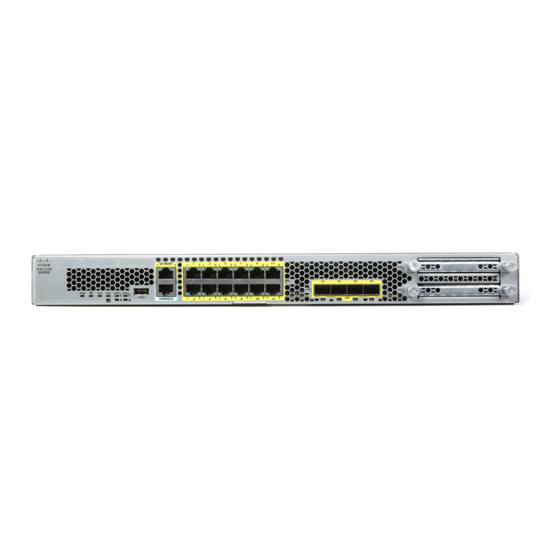
Panel LEDs, on page 9 for a description of the LEDs. Figure 5: Firepower 2110 and 2120 Front Panel Power LED Gigabit Ethernet management port Management 0 (also referred to as Management 1/1 and Diagnostic 1/1) Cisco Firepower 2100 Series Hardware Installation Guide... -
Page 11: Front Panel
SSD 2 System LEDs Type A USB 2.0 port RJ-45 console port Pull-out label card 4 fixed SFP+ (1G/10G) ports Network Module (network module slot Fiber ports 13 through 16 labeled left to right Cisco Firepower 2100 Series Hardware Installation Guide... - Page 12 ◦ Security module log files • Platform bundle image upload using download image usbA: The Type A USB port does NOT support Cisco Secure Package (CSP) image upload support. Network Ports The Firepower 2100 chassis has 12 fixed RJ-45 1G/100M/10M) ports. They are numbered from top to bottom, left to right starting with 1 and are named Ethernet 1/1 through Ethernet 1/12.
-
Page 13: Front Panel Leds
• Solid amber – The system is powering up (before the BIOS boots). This takes one to five seconds at most. • Solid green – The system is fully powered up. Cisco Firepower 2100 Series Hardware Installation Guide... -
Page 14: Front Panel Leds
Ethernet Link • Unlit – SSD has normal activity. • Solid green – The link partner is detected; no activity. • Solid amber – SSD failure. • Blinking green – Network activity is detected. Cisco Firepower 2100 Series Hardware Installation Guide... - Page 15 • Blinking green – Port is enabled; network activity is detected. The following figure describes the Firepower 2130 and 2140 front panel LEDs. Figure 8: Firepower 2130 and 2140 Front Panel LEDs Cisco Firepower 2100 Series Hardware Installation Guide...
- Page 16 • Solid green – The SSD is present; • Solid green – The SSD is no activity. present; no activity. • Blinking green – The SSD is • Blinking green – The SSD is active. active. Cisco Firepower 2100 Series Hardware Installation Guide...
- Page 17 1 link partner is detected. blink=10Mbit, 2=100Mbit, • Solid amber – Port is enabled, 3=1Gbit. but the link partner is not detected. • Blinking green – Port is enabled; network activity is detected. Cisco Firepower 2100 Series Hardware Installation Guide...
-
Page 18: Rear Panel
Power supply module 1 FAIL LED Power supply module 2 FAIL LED Power supply module 1 Power supply module 1 OK LED Fan tray Power supply module 2 Power supply module 2 OK LED Cisco Firepower 2100 Series Hardware Installation Guide... -
Page 19: Network Modules
The network module is NOT hot swappable. Note The Firepower 2130 and 2140 support the Firepower 8-port 10G Network Module single-wide (FPR-NM-8X10G SFP+). The 10 Gigabit Ethernet network module ports are numbered from top to bottom, left to right. Cisco Firepower 2100 Series Hardware Installation Guide... -
Page 20: Network Modules
• See Supported SFP/SFP+ Transceivers, on page 20 for a list of supported SFPS. • See Remove and Replace the Network Module, on page 43 for the procedure for removing and replacing network modules. Cisco Firepower 2100 Series Hardware Installation Guide... -
Page 21: Power Supply Modules
Table 2: AC Power Supply Module Hardware Specifications 2110 2120 2130 2140 Input voltage 100 to 240V AC Maximum current 4A (at 100V AC) 6.3A (at 100V AC) Maximum output 250W 400W power Cisco Firepower 2100 Series Hardware Installation Guide... -
Page 22: Power Supply Modules
The power supply module is rated at 15A but the system power Note is limited to 6.1A. See Hardware Specifications, on page 23 for more system specifications. Maximum output power 350W Redundancy 1+1 redundancy Efficiency at 50% load Cisco Firepower 2100 Series Hardware Installation Guide... -
Page 23: Fans
For More Information • See Remove and Replace the Power Supply Module, on page 46 for the procedure for removing and replacing the power supply module in the Firepower 2130 and 2140. Cisco Firepower 2100 Series Hardware Installation Guide... -
Page 24: Fans
SSD LEDs on the front panel. • See Remove and Replace the SSD, on page 45 for the procedure for removing and replacing the SSD. Supported SFP/SFP+ Transceivers Take note of the following warnings: Cisco Firepower 2100 Series Hardware Installation Guide... -
Page 25: Ssds
It is a hot-swappable optical interface that plugs into the SFP/SFP+ ports on the fixed ports and the network module ports, and provides Ethernet connectivity. Figure 13: SFP Dust plug Bail clasp Receive optical bore Transmit optical bore Cisco Firepower 2100 Series Hardware Installation Guide... - Page 26 The 1G transceivers are limited to 1GB operation only (no auto-negotiation support). 100M/10M modes Note are not supported. Although non-Cisco SFPs are allowed, we do not recommend using them because they have not been Caution tested and validated by Cisco. Cisco TAC may refuse support for any interoperability problems that result from using an untested third-party SFP transceiver.
-
Page 27: Hardware Specifications
SFP-10G-AOC7M SFP-10G-AOC10M Hardware Specifications The following table contains hardware specifications for the Firepower 2100 series security appliance. Specification 2110 2120 2130 2140 Physical Form factor 1 RU Fits standard 19-in (48.3-cm) square-hole rack. Cisco Firepower 2100 Series Hardware Installation Guide... -
Page 28: Hardware Specifications
Nonoperating: -40⁰ to 149°F (-40⁰ to 65°C) maximum altitude is 40,000 ft Humidity Operating: 10 to 85 percent noncondensing Nonoperating: 5 to 95 percent noncondensing Altitude Operating: 10,000 ft maximum Nonoperating: 40,000 ft maximum Cisco Firepower 2100 Series Hardware Installation Guide... - Page 29 2130 2140 Acoustic Noise Sound pressure 47.3 dBA (typical) 55.7 dBA (typical) 73.4 dBA (maximum) 76.7 dBA (maximum) Sound power 60.2 (typical) 66 (typical) 85.1 (maximum) 84.5 (maximum) Air flow Front to back Cisco Firepower 2100 Series Hardware Installation Guide...
- Page 30 Overview Hardware Specifications Cisco Firepower 2100 Series Hardware Installation Guide...
-
Page 31: Installation Preparation
Use the statement number provided at the end of each warning to locate its translation in the translated safety warnings that accompanied this device. SAVE THESE INSTRUCTIONS Cisco Firepower 2100 Series Hardware Installation Guide... - Page 32 To avoid electric shock, do not connect safety extra-low voltage (SELV) circuits to telephone-network voltage (TNV) circuits. LAN ports contain SELV circuits, and WAN ports contain TNV circuits. Some LAN and WAN ports both use RJ-45 connectors. Use caution when connecting cables. Cisco Firepower 2100 Series Hardware Installation Guide...
- Page 33 This product requires short-circuit (overcurrent) protection to be provided as part of the building installation. Install only in accordance with national and local wiring regulations. Warning Statement 1074—Comply with Local and National Electrical Codes Installation of the equipment must comply with local and national electrical codes. Cisco Firepower 2100 Series Hardware Installation Guide...
-
Page 34: Safety Recommendations
◦ Determine whether the person needs rescue breathing or external cardiac compressions; then take appropriate action. • Use the chassis within its marked electrical ratings and product usage instructions. Cisco Firepower 2100 Series Hardware Installation Guide... -
Page 35: Prevent Electrostatic Discharge Damage
• Check the power at the site before installing the chassis to ensure that it is “clean” (free of spikes and noise). Install a power conditioner, if necessary, to ensure proper voltages and power levels in the appliance input voltage. Cisco Firepower 2100 Series Hardware Installation Guide... -
Page 36: Equipment Rack Configuration Considerations
• Baffles can help to isolate exhaust air from intake air, which also helps to draw cooling air through the chassis. The best placement of the baffles depends on the airflow patterns in the rack. Experiment with different arrangements to position the baffles effectively. Cisco Firepower 2100 Series Hardware Installation Guide... -
Page 37: Mount And Connect
C H A P T E R Mount and Connect This chapter describes how to rack-mount the Cisco Firepower 2100 security appliance, and how to connect the cords and cables. It contains the following sections: • Rack-Mount the Chassis, page 33 •... - Page 38 • Firepower 2100 kit that contains the following: ◦ One slide rail set ◦ Two brackets with captive screws ◦ Six 8-32 0.25" screws ◦ Two M3x6mm screws ◦ Six 8-32" shoulder screws Cisco Firepower 2100 Series Hardware Installation Guide...
- Page 39 Step 2 Attach the inner rails to the sides of the chassis: a) Remove the inner rails from the slide rail assemblies. b) Align an inner rail with each side of the chassis: Cisco Firepower 2100 Series Hardware Installation Guide...
- Page 40 Set the keyed slots over the screws/pegs, and then slide the rail toward the front to lock it in place on the screw/pegs. The rear key slot has a metal clip that locks over the screw/peg. d) Using one M3X6mm screw, secure the inner rail to the side of the chassis to prevent sliding. Cisco Firepower 2100 Series Hardware Installation Guide...
- Page 41 Pull the inner slide rails on each assembly out toward the rack front until they hit the internal stops and lock in place. Step 5 Insert the chassis into the slide rails. Cisco Firepower 2100 Series Hardware Installation Guide...
-
Page 42: Ground The Chassis
This equipment must be grounded. Never defeat the ground conductor or operate the equipment in the absence of a suitably installed ground conductor. Contact the appropriate electrical inspection authority or an electrician if you are uncertain that suitable grounding is available. Cisco Firepower 2100 Series Hardware Installation Guide... -
Page 43: Connect Cables, Turn On Power, And Verify Connectivity
Statement 1005—Circuit Breaker This product relies on the building's installation for short-circuit (overcurrent) protection. Ensure that the protective device is rated not greater than: Rated 120 V, 15 A (US), 250 V, 16A (EU) Cisco Firepower 2100 Series Hardware Installation Guide... - Page 44 Management Center ) to initially set up the Firepower 2100. Step 2 Connect the management interface. Install the management cable that was provided in the Firepower 2100 accessory kit in the Management port, Cisco Firepower 2100 Series Hardware Installation Guide...
- Page 45 Caution Although non-Cisco SFPs are allowed, we do not recommend using them because they have not been tested and validated by Cisco. Cisco TAC may refuse support for any interoperability problems that result from using an untested third-party SFP transceiver.
- Page 46 Step 9 See the quick start guide for your operating software to configure the Firepower 2100 series security appliance. • Cisco Firepower Threat Defense for the Firepower 2100 Series Using Firepower Device Manager Quick Start Guide • Cisco Firepower Threat Defense for the Firepower 2100 Series Using Firepower Management Center Quick Start...
-
Page 47: Maintenance And Upgrades
You can remove and replace the network module in the Firepower 2130 and 2140. Although the hardware supports removing and replacing the network module while the system is running, the software does not Cisco Firepower 2100 Series Hardware Installation Guide... - Page 48 Power on the chassis so that the new network module is recognized. What to Do Next Follow the procedures in the FXOS Configuration Guide to connect to the network module and make sure that it has been discovered correctly by the security appliance. Cisco Firepower 2100 Series Hardware Installation Guide...
-
Page 49: Remove And Replace The Ssd
You can install a Malware Storage Pack (MSP) in slot 2. The MSP stores threat detection data for use in future analysis. It supports the Advanced Malware Protection (AMP) software feature. It is used as both storage and as the Malware application repository. RAID is not supported. Cisco Firepower 2100 Series Hardware Installation Guide... -
Page 50: Remove And Replace The Power Supply Module
Check the SSD LED to make sure the SSD is operative. See Front Panel LEDs, on page 9 for a description of the SSD LEDs. Remove and Replace the Power Supply Module Take note of the following warnings: Cisco Firepower 2100 Series Hardware Installation Guide... - Page 51 Statement 1046—Installing or Replacing the Unit Warning When installing or replacing the unit, the ground connection must always be made first and disconnected last. Statement 1073—No User-Serviceable Parts Warning No user-serviceable parts inside. Do not open. Cisco Firepower 2100 Series Hardware Installation Guide...
-
Page 52: Connect The Dc Power Supply Module
Power Supply Modules, on page Connect the DC Power Supply Module Take note of the following warnings: Statement 1030—Equipment Installation Warning Only trained and qualified personnel should be allowed to install, replace, or service this equipment. Cisco Firepower 2100 Series Hardware Installation Guide... - Page 53 No user-serviceable parts inside. Do not open. For the Cisco 2130 and 2140, the input connector and plug must be UL recognized under UL 486 for field wiring. The connection polarity is from left to right: negative (–), positive (+), and ground.
- Page 54 Do not overtorque the terminal block captive screws. Make sure that the connection is snug, but the wire is Caution not crushed. Verify by tugging lightly on each wire to make sure that they do not move. Cisco Firepower 2100 Series Hardware Installation Guide...
-
Page 55: Secure The Power Cord On The Power Supply Module
To secure the power supply module against accidental removal and thus prevent disrupting system performance, use the tie wrap and clamp provided in the accessories kit that ships with your Firepower 2100 security appliance. Take note of the following warnings: Cisco Firepower 2100 Series Hardware Installation Guide... - Page 56 (see the following figures). b) Plug the snapping portion of the tie wrap into the hexagonal hole. c) With the clamp side facing up, push the tie wrap in until it is fully engaged. Cisco Firepower 2100 Series Hardware Installation Guide...
- Page 57 Adjust the clamp position on the tie wrap so that the clamp is tight against the front of the over mold and the power cord cannot be removed by lightly pulling on it. Figure 28: Clamp on Over Mold of Power Cord Cisco Firepower 2100 Series Hardware Installation Guide...
-
Page 58: Remove And Replace The Fan Tray
The appliance will not power up and boot properly if the fan tray is missing. Take note of the following warnings: Statement 1030—Equipment Installation Warning Only trained and qualified personnel should be allowed to install, replace, or service this equipment. Cisco Firepower 2100 Series Hardware Installation Guide... -
Page 59: Install The Optional Cable Management Brackets
You can install the optional cable management bracket on all models of the 2100 series. The optional cable management bracket kit comes with 2 cable management brackets and four 8-32 x 0.375" screws. Take note of the following warnings: Cisco Firepower 2100 Series Hardware Installation Guide... - Page 60 Install two 8-32" screws through the inside of the rack mount bracket to secure the cable management bracket to rack mount bracket. Figure 31: Attaching the Cable Management Bracket to the Rack Mount Bracket Cisco Firepower 2100 Series Hardware Installation Guide...
- Page 61 Figure 32: Installing the Rack Mount Bracket to the Chassis What to Do Next Continue with installing the chassis in the rack. See Rack-Mount the Chassis, on page Cisco Firepower 2100 Series Hardware Installation Guide...
- Page 62 Maintenance and Upgrades Install the Optional Cable Management Brackets Cisco Firepower 2100 Series Hardware Installation Guide...