Table of Contents
Advertisement
Quick Links
Advertisement
Table of Contents

Related Manuals for Yudor YDS-16

Summary of Contents for Yudor YDS-16
-
Page 1: User Manual
User Manual 16/25/36CH SMART PoE NETWORK VIDEO RECORDER V2.1_1608... - Page 2 WARNING TO REDUCE THE RISK OF FIRE OR ELECTRIC SHOCK, DO NOT EXPOSE THIS PRODUCT TO RAIN OR MISTURE. DO NOT INSERT ANY METALLIC OBJECT THROUGH VENTILATION GRILLS. CAUTION CAUTION RISK OF ELECTRIC SHOCK DO NOT OPEN CAUTION:TO REDUCE THE RISK OF ELECTRIC SHOCK. DO NOT REMOVE COVER (OR BACK).
-
Page 3: Fcc Compliance
FCC Compliance USER-INSTALLER CAUTION: YOUR AUTHORITY TO OPERATE THIS FCC VERIFIED EQUIPMENT COULD BE VOIDED IF YOU MAKE CHANGES OR MODIFICATIONS NOT EXPRESSLY APPROVED BY THE PARTY RESPONSIBLE FOR COMPLIANCE TO PART 15 OF THE FCC RULES. NOTE: THIS EQUIPMENT HAS BEEN TESTED AND FOUND TO COMPLY WITH THE LIMITS FOR A CLASS A DIGITAL DEVICE, PURSUANT TO PART 15 OF THE FCC RULES. -
Page 4: Table Of Contents
i. Live Mode ....................5 (Note: All examples are based on mainly 36CH version) * Quick Setup ..................5 * Main Menu ..................12 * Live Video...................36 * Side Menu…………….................42 ii. Playback Mode..................51 * Timeline Menu ...................51 * HDD Playback ...................58 iii. Remote Control Mode................62 * PC Site Setup ..................62 * Remote Control .................65 iv. -
Page 5: I. Live Mode
i. Live Mode (Note: All examples are based on mainly 36CH version) *Quick Setup There are some important settings you may need to execute FIRST before you continue with other settings. The Wizard Setup system offers a quick and easy way to help you set up your NVR. It should automatically start on its own if you are using the NVR for the first time. - Page 6 Please be sure that the connection is established within the same network environment which allows all the online devices accessible through NVR operations. B. Confirm your NVR password If you are operating the NVR for the very first time, you will need to set up your administrator password.
- Page 7 The system will require your confirmation of the password you have just entered. From here on in, you will be able to establish connection with your IP cameras or you may choose to do so later. Click on Next to go on to the next step or Exit to stop the setting up. Once clicked, a message window will pop up and recommend you to reset your NVR back to default since the default password is admin.
- Page 8 Click to look for any online device connected in the same network as the NVR. Clicking on the IP Address from the list will import the device information to the channel without manually entering step. Click Rescan to search for IP device again. It is usually for updating an operation after disconnection or new device has been installed.
- Page 9 Tick Synchronize with NTP Server, the NVR will be synchronized with the NTP Server. After ticking the Enabling the Daylight Saving checkbox, the user can use the drop down list to select the start time and the end time of daylight saving time.
- Page 10 Clicking on will lead you to the page where you must be verified as the administrator first by entering the user name and password to execute formatting the HDD. Click on Next to go on to the next step or Exit to stop setting further. E.
- Page 11 A message window of notice will pop up and inform you that the setup is complete.
-
Page 12: Main Menu
*Main Menu The Main Menu consists of icons used for most NVR operations. Move the mouse cursor on the icon of your choice and it will be highlighted in blue. Click on the left mouse button to start the operation. 1. - Page 13 A-1. Network Setup DHCP: The NVR will get all the network parameters automatically. Tick to enable DHCP Server setup. Static IP: Type-in the IP Address, Subnet Mask, Gate Way, and key-in DNS1 and DNS2 that provided by ISP. Tick Enable PPPoE to Insert the User Name, Password which provided from local ISP, and check the current State of PPPoE function.
- Page 14 UpnP If the network camera supports UPnP, you can enable this function and the NVR will automatically detect what device is connected in the same LAN. UPnP Port Forwarding Tick its checkbox for accessing the NVR from the Internet; this option allows the NVR to open ports on the router automatically so that video streams can be sent out from a LAN.
- Page 15 A-3. IP Filter Tick either Enable Blocked list or Enable Allow list for blocking or allowing any online visitor with the IP addresses entered in the IP Filter list. A-4. SNMP Enable SNMPv1, SNMPv2c: write the name of both Read/Write and Read only community.
- Page 16 B. Camera B-1. Audio and Video Audio and Video Parameter Click to highlight a camera title to from the ones listed above. The Audio and Video Parameter menu will be functional. Edit the video parameters in various settings from Video, Audio, Image, Motion, Mask, and click on Save button to keep the change.
- Page 17 Quality: Click the drop down list to change the image quality. For H.264 IP Cam above 1 Megapixel, the resolution options support 1M, 2M, 4M, 6M, 8M. For H.264 IP Cams, less than 1 Megapixel, the resolution options include Best, High, Standard, Medium, and Low.
- Page 18 Mask A masked area will be hidden in the live view and playback recording modes. Tick the “Area1/2/3” box and click “Mask Area Setup”. Start dragging your masked areas in blue, green or red by clicking your mouse anywhere on the screen.
- Page 19 C. Schedule Recording Schedule C-1. Enable Scheduled recording Choose a camera which you would like to assign your Recording Schedule to. Ticking on Enable scheduled recording to edit Schedule Settings. Different colours imply the type of recording selected. Select a type of recording from Continuous recording, Record on event, Record on motion, Record on digital input, then draw a timeline bar with the mouse button on the timeline from Sunday(Sun) to Saturday(Sat).
- Page 20 C-2. Enable audio recording The sound received from the digital output of the camera device will also be recorded as part of the video file. C-3. Enable Automatic Overwrite Allow video file saved from recording to be overwritten when the space of disk storage is full.
- Page 21 SMTP Settings Set the Sender Email address, Server Address, UserName, and Password, Port for an email account to be sent to when events occur. Contact Fill in the contact details of the sender. D-2. E-Map Settings Setting up an E-map helps you set up cameras in a more efficient manner. You can easily identify your camera locations in visual layout and browse your monitoring area as a whole system of a surveillance network.
- Page 22 To delete, select the E-map node and click on Delete button on top. Adding the camera Highlight a camera of the list, then hold and drag the highlighted camera name out of the list with your mouse. There will be a camera icon displayed, place and drop the icon anywhere by releaseing your mouse button.
- Page 23 Click Copy to choose other channels which you may apply the same settings to. System Event Settings Set up the type of Event Action which you would like to proceed when any of the Event selections is triggered after its checkbox is ticked. D-4.
- Page 24 View different system logs and you can download each Log to your storage device by clicking on the Download icon. Click on the arrow icon to view logs past and present. Clear the whole log with clear icon. D-5. Door Security Tick Enable Port to continue the Door Security Setting.
- Page 25 Choose output in Type, assign output relay/buzzer device to any channels within Trigger Record, and arrange the Buzzer time / RelayDwell Time for the alarming time duration. Tick Email to set up the receiver’s email address for alarming message to be sent to, and tick PTZ preset to set up a channel assigned with a PTZ camera.
- Page 26 Tick different checkboxes for the OSD to display contents from Camera Name to Frame rate. Adjust the OSD texts in Size, Color, and styles such as Bois and Italic. E-2. User Account The administrator can set up the user management permission & user authority management.
- Page 27 The user can also load settings to factory default by clicking on Restore. Browse and Load up the configuration from USB device for returning the NVR settings back to how it was saved by clicking on Save button to keep the previous settings of the NVR.
- Page 28 Time Zone Adjust the Time Zone of your current location. Daylight Saving Time After ticking Enable Daylight Saving checkbox, the user can use the drop down list to select the Start Time and the End Time of daylight saving time. Tick either Auto set Daylight Saving for the NVR to set the time automatically or Manual set Daylight Saving to set your time manually.
- Page 29 Storage Information Information of the storage device will be displayed on this page. Clicking on the CAUTION button will lead you to the S.M.A.R.T Status table where user may check on the defection of the hard disk. Your Hard Disk Device needs to be replaced if its health condition is displayed with a WARNING! text under the Health Status.
-
Page 30: Camera Search
3. Camera Search Helps connect and operate the IP camera from your NVR. Be sure your IP cameras and NVR are connected in the same LAN. Click on the icon to enter Camera Search window. Clicking on to search for the IP cameras online. As demonstrated in the image above, click on the “+”... - Page 31 A-2. RTSP Mode A-3. ROI Mode This function allows users to set up The NVR only supports IP address a channel as an attached channel indication, live video, and video which based on a normal/RTSP recording under RTSP Mode. Other channel that has been set up, and functions like motion detection are can display the same live view as...
- Page 32 C. Set Default Clicking on can re-edit the user account of the IP camera. D. IP Installer Clicking on to enter the IP Installer intereface. Highlight one of the IP camera devices enlisted in the column on the left after clicking Search to enable editting of the camera from IP Address to Port number.
- Page 33 4. Album Offers to keep the snapshot files taken by NVR in either HDD or USB drive. Take a snapshot by clicking Save Jpeg icon from Side Menu or selecting Snap Shot from Fast Switch Menu. The snapshots will be saved to HDD as the default storage device.
- Page 34 5. Back Up Offers to set up and manage video back-up files. Choose to either automatically or manually to back up the files and you can also choose the destination for back up files. A. Auto Backup Schedule Choose to back up the recorded files automatically or manually. You may also assign where the backup files are saved from this interface.
- Page 35 6. Help Offers everything needed to know about NVR operations in different topics. Select a title and roll the middle button of the mouse to scroll down the article and read on. 7. Live Remote Control Mode only) Click on the icon to return to Live interface while you are in other modes.
-
Page 36: Live Video
*Live Video A. Live Video Control signs may appear on top of the NVR live video control panel while the NVR is undergoing a different operation. User may also check on the time displayed on the panel to adjust NTP Server settings. - Page 37 B. Screen Mode Display Click the right mouse button on a specific channel to enable a fast switch menu for operating that channel. B1. Enable EPTZ: Select to digitally zoom and navigate the camera’s viewable area by press & holding the block in the EPTZ mini window.
- Page 38 B4. Full Screen: Browse through single channel or multiple channels in full screen. To exit, right-click the mouse button to deselect the option again. B5. Fast Playback: Drag the red anchor line with your mouse to pick the timeline which has your playback video recorded. Pause or play to watch the playback video of the selected channel.
- Page 39 B10. 9 Split: Select 9 channels to be displayed in a 9 cameras split screen. B11. 10 Split: Select 10 channels to be displayed in a 10 cameras split screen. B12. 13 Split: Select 13 channels to be displayed in a 13 cameras split screen.
- Page 40 B15. 36 Split: Select 25 channels to be displayed in a 25 cameras split screen. B16. Status Display: On top of the right corner of Video Loss each channel screen, various icons are displayed indicating different status. Recording When any of the situations on the left occurs, an image Motion Trigger of small icon will be...
- Page 41 *Side Menu Side Menu consists of Display Controller, Camera List, PTZ Controller, System Information, Storage Information, Log, E-Map, and Digital Output. You are able to scroll the Side Menu up & down by rolling up & down the middle mouse button. 1.
-
Page 42: Side Menu
Check/uncheck titles: Reveal/hide any title including its control panel. Select from Display Controller to Digital Output to reveal/hide on the Side Menu. A title is only functional when it is checked in Layout Switch Menu. Open All: Select to reveal/spread out Collapse All: Select to hide all the all the control panels of Side Menu. - Page 43 Choose different screen patterns to display the NVR live channel screen. ii. Full Screen Click on the icon to enter full-screen mode. To exit this mode, right-click the mouse button to deselect the option again. iii. Auto Swap Click on the icon to start switch dwell. The duration of the interval happens in every 8 seconds.
-
Page 44: Camera List
viii. Backup Click on the icon for the Backup window to appear. Click Select to confirm your backup time, and tick on checkboxes to assign your backup source channel. At last, click Save to execute the back up. ix. Audio Enabled Disabled Click this icon to enable the audio volume control bar. - Page 45 A pop-up window will appear and the default user’s account name and password will be required to proceed. You can also select the camera type for its Vendor brand to limit your selection. Click OK to allow the NVR to automatically assign IP addresses to the IP Cameras for getting quick and easy connection.
- Page 46 v. Preset Name Choose a camera view which you would like to assign your preset point to. Create the preset name of your preset point by selecting the drop down menu of Go to Preset, select any number indicating nonsetting, then click on the blank space column of Preset Name to create a name as you like in "...
-
Page 47: System Information
xii. Stop Click to stop the camera during its Patrol or auto Auto Pan route. 5. System Information Displays the system information of the NVR. 6. Storage Information Displays the storage information of the NVR. - Page 48 7. Log Tick System, NVR, Event to view different logs recorded. 8. E-Map Graphically allow you to set up cameras in a visual layout of your surveillance area. Select an E-Map to see its layout in plan. Please refer to the E-Map settings from Main Menu for more details.
-
Page 49: Digital Output
9. Relay Click on/off to turn on/off the pictorial network relay device which is assigned to the NVR output in connection. 10.Digital Output Click on/off to turn on/off the pictorial network digital output device which is assigned to the NVR output in connection. - Page 50 11. Askyviewer Pro P2P (Optional) Install Askyviewer Pro App on your mobile phone to access P2P operations which allow users to watch IP Camera live view on their mobile phones. Once the installation is done, either enter the P2P ID from the IP camera web browser, or simply scan the QR Code to help you log in to your IP camera through Askyviewer Pro App and watch the live view...
-
Page 51: Ii. Playback Mode
ii. Playback Mode *Timeline Menu A. Timeline Menu Hold and drag the Recorded Video Data on the timeline to the Anchor Line with your mouse to enter playback mode. Select the Recorded Video Data from the last (1 hour), (2 hours), (12 hours), and (24 hours) range of timeline. - Page 52 D. Playback Drag the whole timeline to the left by holding your mouse on the left button. Release it on the time point where there is recorded data. Start Click to replay the playback video. The sign will appear on top of the right screen. E.
- Page 53 First, select a channel of your search range preference. Next, click on Set Search Time from the Date Time Period menu. Once it is clicked, another window of View Record Files will pop up. Pick any date from the calendar on the top left corner to set the search range. Please refer to Chapter E.
- Page 54 Place your mouse cursor on the timeline to locate the time frame you prefer. Use the magnifying glass icon to zoom in/out for you to browse through the timeline. Hold and drag the timeframe of your preference with your mouse. You will see the part where there is event triggering highlighted.
- Page 55 Back to the Playback Search Window. Select an Alarm Event Type from the drop down list and go to Region Definition. Region Definition will help you define the search area of the playback video image, and enlist all the events in Search Result. You can either draw an area of Region Definition on the playback video screen or simply click All to include the whole screen.
- Page 56 Click on Save Jpeg icon to save any image into your Album. Click on the Backup icon to back up the playback video file in a connected output device. Adjust the Level of the sensitivity of your search from 1 ~ 10 by selecting the level of the or dragging the red line in the graph below.
- Page 57 Click on Search to proceed with the Smart Search scan. While it is scanning, a window will pop up to show the progress of the search. You can stop anytime during the search by clicking on Cancel. In the Search Result column you will be able to see all the events found from this search.
-
Page 58: Hdd Playback
*HDD Playback 1. MAIN SCREEN SETTING (QT Viewer) QT Viewer is used for playing the NVR backup video. It can be obtained from the CD content in the Applications/HDD Player folder. A. MAIN SCREEN Open the QT Viewer. Each buttons is labeled by its function. B. - Page 59 Click “Add” Assign a letter to the HDD, then click “OK” so that the HDD get a drive letter and can be recognized by Windows.
- Page 60 C. Open HDD Click the HDD Choose icon or select a hard drive under the Open HDD drop down list to load the video files inside. Click the icon to quit reading the hard disk drive. Click the icon to view the events from a pop-up window.
- Page 61 D. Backing Up Your Video Click to choose the path where the backup file is going to be saved. Select the channel of the video recorded, set the Start time and End time. Choose the backup format of the video (AVI or MKV). Click to pause the backup.
-
Page 62: Iii. Remote Control Mode
iii. Remote Control Mode *PC Site Setup SYSTEM REQUIREMENT SUGGESTED REQUIREMENT CPU: Intel Celeron 1.6G CPU: Intel P4 2.8G MEMORY: 256MB. MEMORY:512MB or above VGA: 32MB VGA: 64MB or above VGA RESOLUTION: 1024 x 768. VGA RESOLUTION:1024 x 768 OS: Windows XP / 2000 OS: Windows XP / 2000 NETWORK BANDWIDTH: Upload Speed is 256kbps or above... - Page 63 NOTE: Please input correct network parameters without blank spaces. On “Device Lists”, the software lists all servers. By clicking on the server the IP settings will be show on the right side. After editing the parameters and clicking on “Submit”, the following dialogue box will popup.
-
Page 65: Remote Control
*Remote Control Before operating the NVR remotely, please refer to PC Site Setup to check whether your PC settings are compatible with the NVR system or not. Remote User Log In Open the IP Scanner, and double-click on the NVR name. Enter admin for both the default Username and Password. - Page 66 If the NVR remote control interface is not displayed properly, there will be a message appearing as below, notifying the user to install the plugin first to enable any further remote operation. Click on the message to begin downloading the plugin. Locate the plugin and click on the right button of the mouse to execute this downloaded file.
- Page 67 Live Video Screen Please note that the Screen Mode Display is not available in Remote Control mode. 1. Main Menu The Main Menu consists of icons used for most NVR operations. Move the mouse cursor on the icon of your choice and it will be highlighted in blue.
- Page 68 D. Album Offers to keep the snapshot files taken by NVR in either HDD or USB drive. Please read the Album chapter from Main Menu for more details. E. Back Up Offers to set up and manage video back-up files. Please read the Album chapter from Main Menu for more details.
- Page 69 Timeline Menu Please refer to Timeline Menu for more details.
-
Page 70: Iv. Appendix
iv. Appendix *Product Specifications A. Features: Support up to 36 channel H.265 IP camera Support 16 channel PoE for IP cameras input. Power management for PoE channel. Support 5 Megapixel IP Camera for each channel Plug &... - Page 71 Power Input AC100~240V Power Output RJ-45 x 16, PoE 802.3at; Max. Power supply: 190W Video and Audio IPCam Video input 16 channels Split screen display 1, 4, 9, 16 1, 4, 9, 16, 25 1, 4, 9, 16, 25, 36 Decompression H.265, H.264 IP Cam Resolution...
-
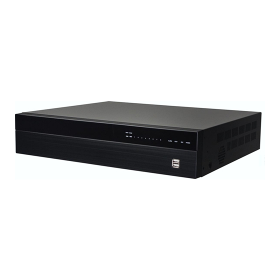
Page 72: Hardware Overview
*Hardware Overview 1. Connectors A. FRONT PANEL NVR OPERATION LABEL OPERATION USB Connector/ USB Mouse Connector RJ-45 connector 1~16 CHANNEL LED indicators ALARM/EVENT/REC/POWER LED indicators EVENT REC POWER B. BACK PANEL... - Page 73 NVR OPERATION LABEL OPERATION POWER OVER RJ-45 connector with power supply ETHERNET (PoE) RJ-45 connector (for switch connection) eSATA External storage 4 alarm in / 1Relay out / RS485 Audio In Microphone input(Phone Jack) (None) HDMI HDMI video output USB Connector / USB Mouse Connector Audio Out Earphone output(Phone Jack) VGA OUT...
-
Page 74: Network Configuration
B Connect the HDD into the NVR C Refit the top cover and screw the screw back. For a detailed Hard Disk Compatible Table, please refer to the Compatibility Table from the attached CD Contents. 3. Network Configuration PoE (Power Over Ethernet) Referring to POWER OVER ETHERNET in 1~4 from Connectors chapter. - Page 75 Power over Ethernet (PoE) is a technology that integrates power into a standard LAN infrastructure, enabling power to be provided to a network device using the same cable as the network connection. IP cameras can be installed for uninterruptible power supplies without power outlets in various locations.
-
Page 76: Alarm Inputs
ALARM IN CONNECTION RS-485: sends +/ receives + RS-485: sends -/ receives - Ground ALARM IN 1-2 Alarm inputs Relay: Normally close Relay: Normally open Relay: Common EX1:Connect GND & Alarm to external IR EX2:Connect N.O & COM to external siren. detector. - Page 77 NETWORK ENVIRONMENT RECOMMENDATION When setting up 4Mbps per channel, it’s not recommended to connect more than 25 IP cameras under a 10/100 switch. It is suggested to connect 1~16 IP cams on each 10/100 switch when you setting up 4Mbps per channel. Make sure of using Cat.6 Ethernet cable when connecting a Giga switch.
- Page 78 Under “Two Core” connection, the controller can control the speed dome without any built-in protocol into the NVR. Moreover, one keyboard can be connected to a of MAX 256 units. 4. Hardware Default Follow the steps to set back the NVR to its default value. A.
- Page 79 B. Remove the NVR hardware cover and find the Default button which is positioned on the main board. C. Press and hold the button for 20 seconds until you see the message on the monitor. D. Select ”Yes”, all the NVR settings will be restored to default values. Released the button, an admin account will be set to default password, and all the user accounts will be deleted.
-
Page 80: Package Contents
*Package Contents Quick INSTALLATION Adaptor Guide Power cord Mouse CD Disk Screw Package • The CD includes user manual and software tools... -
Page 81: Hdd Compatibility Table
*HDD Compatibility Table Brand Model Capacity Others ST3500320SV 500GB SV35.3 ST3500410SV 500GB SV35.5 ST3500413AS 500GB S3 Barracuda 7200 12 ST3500418AS 500GB 7200 12 ST500NM0011 500GB ST500DM002 500GB S3 Barracuda ST31000333AS 7200 11 ST31000340AS 7200 11 ST31000340NS Barracuda ES.2 ST31000340SV SV35.3 ST31000322CS Pipeline HD .2 ST31000525SV... - Page 82 WD5000AVDS 500GB AV-GP WS5003ABYX 500GB Enterprise Storage WD5000AAKX 500GB Caviar Blue WD5000AUDX 500GB AV-GP WD5003AZEX 500GB Caviar Black WD6400AAKS 640GB 7200 BLUE WD6400AVVS 640GB 7200 GP WD7500AACS 750GB 7200 GP WD7500AVVS 750GB 7200 GP WD1003FBYX Enterprise Storage WD1002FAEX Caviar Black WD10EACS 7200 GP WD10EADS...
- Page 83 HDS721616PLA380 160GB 7200 HDT725025VLA380 250GB 7200 HDT725032VLA360 320GB 7200 HDP725050GLA360 500GB 7200 HCP725050GLA380 500GB 7200 HDS721050CLA362 500GB HITACHI HDT721010SLA360 7200 HDS721010CLA332 7200 HDS721010CLA362 HDS721010DLE630 7200 HDS722020ALA330 7200 HDS723020BLA642 7200 DS7SAE202 DT01ACA050 500GB DT01ACA100 DT01ACA200 DT01ABA050V 500GB TOSHIBA DT01ABA100V DT01ABA200V DT01ACA300 DT01ABA300V...