Honeywell DC1010 Product Manual
Hide thumbs
Also See for DC1010:
- Instruction manual (9 pages) ,
- Wiring diagram (4 pages) ,
- Product manual (60 pages)
Table of Contents
Advertisement
Before using this manual, please check whether the range, input and output match
your requirement.
1.
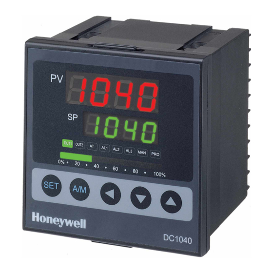
Front Panel Instruction
1.1
Display
PV
:Process Value, 4-digit display (red color)
SP
:Set Point, 4-digit display (green color)
1.2
LED
OUT1
:Output 1, green color
OUT2
:Output 2, green color
AT
:Auto-Tuning, yellow color
PRO
:Program, yellow color
AL1
:Alarm 1, red color
AL2
:Alarm 2, red color
MAN
:Manual, yellow color
1.3
Key
SET
:MODE(LEVEL) & SET key
:SHIFT key
:DOWN key
:UP key
A/M
:Auto/Manual key
Auto Tuning
2.
2.1
Once AT set 'YES', auto tuning is to be performed.
2.2
After auto tuning finished, PID parameter is to be set automatically.
2.3
ATVL = auto tuning offset, and it will be deduced from SP.
(It prevents over-shooting during auto tuning)
SP-ATVL = Auto-tuning value, ATVL = Auto tuning offset
Ex.) SP = 200°C, ATVL = 5, Auto tuning point is at 195°C
* ATVL means auto-tuning point (195°C) in program type model
2.4
Auto tuning failure
2.4.1 ATVL is too big
If no sure, set ATVL = 0)
2.4.2 System time is too long.
Set PID parameter individually.
DC1010/1020/1030/1040 PRODUCT MANUAL
1
1
Advertisement
Table of Contents

Related Manuals for Honeywell DC1010


Summary of Contents for Honeywell DC1010
- Page 1 Ex.) SP = 200°C, ATVL = 5, Auto tuning point is at 195°C * ATVL means auto-tuning point (195°C) in program type model Auto tuning failure 2.4.1 ATVL is too big If no sure, set ATVL = 0) 2.4.2 System time is too long. Set PID parameter individually. DC1010/1020/1030/1040 PRODUCT MANUAL...
- Page 2 (1) : Press ‘SET’ key. (2) : Press ‘SET’ key for 5sec (3) : when LCK=’1111’, Press ‘SET’ key and ‘ ’key for 5 sec. (4) : when LCK=’0000’, Press ‘SET’ key and ‘ ’key for 5 sec. DC1010/1020/1030/1040 PRODUCT MANUAL...
- Page 3 If any key were not pressed for 1 minute, the display will go to level 1. 4.1.5 Press A/M key to go to level 1, no matter where it is. 4.1.6 If the output percentage is “0”, it means the controller has no output. DC1010/1020/1030/1040 PRODUCT MANUAL...
- Page 4 Return to LCK=0110, To enter Level 1 & 2 and to change the parameters on Level 1 allowed. LCK=0001, To enter Level 1 only and to change SP allowed. ‘P1’ LCK=0101, Nothing allowed except to change LCK. DC1010/1020/1030/1040 PRODUCT MANUAL...
- Page 5 Time set of Alarm 2 Same as ALT 1 Alarm mode of AL3 Range: 00~19 Refer to ‘6.1 Alarm Function Selection’ on P.14 Time set of Alarm 3 Same as ALT 1 Hysterisis of Alarm Range: 0~1000 DC1010/1020/1030/1040 PRODUCT MANUAL...
- Page 6 Range: -1000~1000 Compensate PV Range: LSPL~USPL Unit of PV & SP Range: C, F, A (analog) Soft filter Adjust the response time of PV (the bigger, the faster) (please skip this step) Range: 0.05~1.00 Please skip this step DC1010/1020/1030/1040 PRODUCT MANUAL...
- Page 7 ) for 5 seconds to enter “SET” status. There are SET0.1 to SET9.4 for use. SET No. (SET 0 ~ ∗ Status of SET Status definition ∗ Status of SET 0= lock (skip) ∗ Status of SET 1= open (display) ∗ Status of SET DC1010/1020/1030/1040 PRODUCT MANUAL...
- Page 8 The time to reach until to be desired SP will be decreased. The remainig time to reach the SP will be shown in PARAMETER ‘TMER’. Where, the time of countdown is related to the PV, not segments. DC1010/1020/1030/1040 PRODUCT MANUAL...
- Page 9 Set point for Seg.3 Set point for Seg.8 Set time for Seg.3 Set time for Seg.8 Set output for Seg.3 Set output for Seg.8 Return to Normal(PV,SP) Set point for Seg.4 Set time for Seg.4 Set output for Seg.4 DC1010/1020/1030/1040 PRODUCT MANUAL...
- Page 10 8 or 16 segments. 4) Linking function PTN=1, Proceed pattern1, which contains 8 segments PTN=2, Proceed pattern2, which contains 8 segments PTN=0, linking proceed pattern 1 and 2 ,totally 16 segments (Set PTN1 and PTN2 first, then set PTN=0) DC1010/1020/1030/1040 PRODUCT MANUAL...
- Page 11 5) Other function (*refer to level 4) SET8.1=1 Program repeat SET8.2=0 No power failure SET8.2=1 With power failure function (If power suspended, the controller will keep the memory) SET8.3=0 Program start from 0 SET8.3=1 Program start from PV DC1010/1020/1030/1040 PRODUCT MANUAL...
- Page 12 0.0~1000.0°C/0.0~1832.0°F 0.0~1200.0°C/0.0~2192.0°F 0.0~1600.0°C/0.0~2912.0°F 0.0~1769.0°C/0.0~3216.0°F 0.0~1600.0°C/0.0~2912.0°F 0.0~1769.0°C/0.0~3216.0°F 0.0~1820.0°C/0.0~3308.0°F 0.0~800.0°C/0.0~1472.0°F 0.0~1000.0°C/0.0~1832.0°F 0.0~1200.0°C/0.0~2192.0°F 0.0~1300.0°C/0.0~2372.0°F -199.9~400.0°C/-199.9~752.0°F -199.9~200.0°C/-199.9~392.0°F 0.0~350.0°C/0.0~662.0°F 0.0~2000.0°C/0.0~3632.0°F 0.0~2320.0°C/0.0~2372.0°F 0.0~1300.0°C/0.0~2372.0°F PLII 0.0~1390.0°C/0.0~2534.0°F -199.9~600.0°C/-199.9~999.9°F -199.9~200.0°C/-199.9~392.0°F 0.0~400.0°C/0.0~752.0°F 0.0~400.0°C/0.0~752.0°F 0.0~800.0°C/0.0~1472.0°F * The initial set in factory mode is K2 without any certain requirement. DC1010/1020/1030/1040 PRODUCT MANUAL...
- Page 13 TYPE CODE RANGE -199.9~600.0°C/-199.9~999.9°F -199.9~400.0°C/-199.9~752.0°F -199.9~200.0°C/-199.9~392.0°F Pt100 0.0~200.0°C/0.0~392.0°F 0.0~400.0°C/0.0~752.0°F 0.0~600.0°C/0.0~1112.0°F -199.9~600.0°C/-199.9~999.9°F -199.9~400.0°C/-199.9~752.0°F -199.9~200.0°C/-199.9~392.0°F Pt100 0.0~200.0°C/0.0~392.0°F 0.0~400.0°C/0.0~752.0°F 0.0~600.0°C/0.0~1112.0°F -199.9~600.0°C/-199.9~999.9°F -199.9~400.0°C/-199.9~752.0°F -199.9~200.0°C/-199.9~392.0°F Pt50 0.0~200.0°C/0.0~392.0°F 0.0~400.0°C/0.0~752.0°F 0.0~600.0°C/0.0~1112.0°F -10~10mV/-1999~9999 0~10mV/-1999~9999 0~20mV/-1999~9999 0~50mV/-1999~9999 10~50mV/-1999~9999 DC1010/1020/1030/1040 PRODUCT MANUAL...
- Page 14 Segment end alarm (use for program only) Program run alarm (use for program only) System error alarm-on System error alarm-off On delay timer alarm * Note : “Hold-On” means the alarm does not work at the first time. DC1010/1020/1030/1040 PRODUCT MANUAL...
- Page 15 : Deviation low alarm inhibit 6.2.5 CODE12 : Deviation low alarm no inhibit 6.2.6 CODE03 : High/low alarm inhibit 6.2.7 CODE13 : High/low alarm no inhibit 6.2.8 CODE04/14 : Band alarm 6.2.9 CODE05 : Absolute high alarm inhibit DC1010/1020/1030/1040 PRODUCT MANUAL...
- Page 16 AL1~3, alarm segment no. set iii) ALT1~3, set 0 = flicker alarm set 99.59 = alarm continued set others = on delay time 6.2.14 CODE17 : Program run alarm (program only) 6.2.15 CODE08 : System Error- ON DC1010/1020/1030/1040 PRODUCT MANUAL...
- Page 17 6.2.16 CODE18 : System Error-OFF 6.2.17 CODE19 : on delay timer when PV=alarm SP, it keeps a certain period (set time) before alarm action (Range: 00H00M~99H59M) DC1010/1020/1030/1040 PRODUCT MANUAL...
- Page 18 Modification of HEAT/ALARM HEAT/COOL (on PC board) DC1010 DC1030 DC1020/1040 DC1010/1020/1030/1040 PRODUCT MANUAL...
- Page 19 OUTY = 0, Single output OUTY = 1, Double output OUTY = 2, None OUTY = 3, Motor valve OUTY = 4, Single phase SCR (Single phase control) OUTY = 5, Three phase SCR (Three phase control) DC1010/1020/1030/1040 PRODUCT MANUAL...
- Page 20 Then, AL1/AL2 will be displayed Range = 00.00~99.59 (hour/minute) Example) SP = 100°C, RAMP = 10.00 °C/minute Time(minute) = 10 minute AL1 = 00.10 PV = 25°C °C Time on °C) If PV ≥ SV(100 100°C SOAK Menu PV=25°C DC1010/1020/1030/1040 PRODUCT MANUAL...
- Page 21 (* Use for large EMI affect controller) Function SET A(LEVEL3) If SET A.1 = 1 set, AL1 relay reversed DC1010 is not available. If SET A.2 = 1 set, AL2 relay reversed ‘a’ contact only If SET A.3 = 1 set, AL3 relay reversed If SET A.4 = 0 set, program run alarm...
- Page 22 8.8.1 SET 0.1 = 0 None SET 0.1 = 1 Certain Communication Set(Don’t change it) * Not available for DC1010/1020/1030/1040 8.8.2 SET 0.2 = 0 * Don’t change it SET 0.2 = 1 Rate for AL3 (ALD 3 = 0) 8.8.3...
- Page 23 CL01 = 0, CH01 = 5000 if used for resistance load CL01 = 0, CH01 = 4000 if used for inductor load FAST CONTROLLER FUSE Module Module ** Controller source phase must be same as load source phase DC1010/1020/1030/1040 PRODUCT MANUAL...
- Page 24 Application 2. Three Phase Control -. Available Models: DC1040/DC1040P -. Data Change : OUTY = 5 CYT1 = 0 CL01 = 0, CH01 = 5000 only if used for resistance load CONTROLLER FAST FUSE DIODE/SCR Module 3즤 LOAD 3φ LOAD DC1010/1020/1030/1040 PRODUCT MANUAL...
- Page 25 Application 3. Single Phase Zero Control -. Available Models: DC1030/1040 DC1030P/1040P -. Data Change: OUTY = 0 CYT1 = 1 FAST CONTROLLER FUSE Module TIME CHART: CYCLE TIME = 200 mSEC. DC1010/1020/1030/1040 PRODUCT MANUAL...
- Page 26 OUTY = 0 CYT1 = 1 CONTROLLER RG 1 FAST FUSE RG 2 Module RG 1 TG 1 TG 1 RG 2 TG 2 TG 2 WE CAN SUPPLY HEATER SINK TIME CHART: CYCLE TIME = 200 mSEC. DC1010/1020/1030/1040 PRODUCT MANUAL...
- Page 27 CYT1 = 1~150 sec. (Normally, default set 5 sec.) RUCY = 5~200 sec. * 1. CYT1 is the cycle time of Open/Close 2. RUCY is the running time of motor valve 0~100% MOTOR VALVE CONTROLLER CLOSE OUT2 Relay CLOSE OPEN OPEN OUT1 Relay DC1010/1020/1030/1040 PRODUCT MANUAL...
- Page 28 -. Data Change: OUTY = 4 CYT1 = 0 CLO1=0,CHO1=5000 if use for resistance load CLO1=0,CHO1=4000 if use for inductor load FAST CONTROLLER FUSE TRIAC Module ** Controller source phase must be same as load source phase 1/2W 0.1uf/630V DC1010/1020/1030/1040 PRODUCT MANUAL...