Table of Contents
Advertisement
Quick Links
www.freeservicemanuals.info
SERVICE MANUAL
SPECIFICATIONS
GENERAL
Power requirement
Power consumption
Power on
Power off
Temperature
Operating
Storage
Operating position
Dimensions (W x H x D)
Weight
Maximum recording time
D-VHS (HS)
D-VHS (STD)
D-VHS (LS3)
S-VHS/VHS (SP)
S-VHS/VHS (EP)
VIDEO/AUDIO (D-VHS)
Video format
Audio format
Track composition
Tape speed
Head azimuth
Drum rotation
Tracking system
Recording specification
Main data input rate
Interface
D-VHS DIGITAL RECORDER
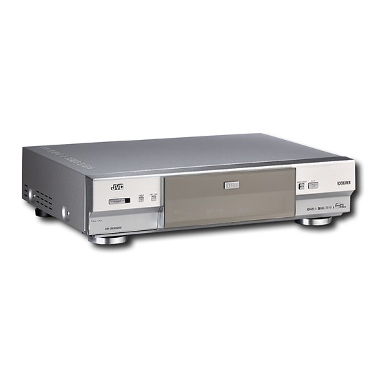
HM-DH30000U
VCR TV CABLE/DBS
A.MONITOR
POWER
A/B
TV/VCR
DISPLAY
ENTER/OSD
1
2
3
. , ?
ABC
DEF
2
4
5
6
GHI
JKL
MNO
DBS
DAILY(M-F)
WEEKLY
7
8
9
PQRS
TUV
WXYZ
C. RESET
AUX
0
4
CANCEL
TIMER
START
STOP
DATE
CH
EXPRESS PROGRAMMING
1
PROG.
HS/STD/LS3
PROG.
SKIP SEARCH
SP/EP
CHECK
PLAY
STOP
TV CH +
TV
TV
TIMER
REC LINK
VOL
VOL
–
+
POWER
TV CH –
JOG/
SHUTTLE
PULL-OPEN
: AC 120 V`, 60 Hz
: 55 W
: 18 W
: 5°C to 40°C (41°F to 104°F)
: –20°C to 60°C (–4°F to140°F)
: Horizontal only
: 435 mm x 105 mm x 383 mm
(17-3/16" x 4-3/16" x 15-1/8")
: 5.7 kg (12.6 lbs)
: 210 min. with DF-420 video cassette
: 420 min. with DF-420 video cassette
: 1260 min. with DF-420 video cassette
: 210 min. with ST-210 video cassette
: 630 min. with ST-210 video cassette
: MPEG2 standard
: Encode
MPEG1 Layer2
Decode MPEG1 Layer2
Dolby Digital
: 33.4 mm/sec (HS mode)
16.67 mm/sec (STD mode)
5.55 mm/sec (LS3 mode)
: ±30 deg
: 1800 rpm
: CTL track system
: 28.2 Mbps (HS mode)
14.1 Mbps (STD mode)
4.7 Mbps (LS3 mode)
: IEEE1394 compliant
DTCP digital copy protection compatible
Published in Heiloo Holland
This service manual is printed on 100% recycled paper.
COPYRIGHT © 2001 VICTOR COMPANY OF JAPAN, LTD.
STOP/EJECT
PL
A
Y
VIDEO/AUDIO (S-VHS/VHS)
Format
: S-VHS/VHS NTSC standard
Signal system
: NTSC-type color signal and EIA monochrome
signal, 525 lines/60 fields
Recording/
Playback system
: DA-4 (Double Azimuth) head helical scan system
Signal-to-noise ratio
: 45 dB
Frequency range
Normal audio
: 70 Hz to 10,000 Hz
Hi-Fi audio
: 20 Hz to 20,000 Hz
TUNER
Tuning system
: Frequency-synthesized tuner
Channel coverage
VHF
: Channels 2–13
UHF
: Channels 14–69
CATV
: 113 Channels
TIMER
Clock reference
: Quartz
Program capacity
: 1-year programmable timer/24 programs
Memory backup time
: Approx. 60 min.
CONNECTORS
Input/Output
: i.LINK IN/OUT, DV IN x 2 (4-pin, S200)
RCA connectors (IN x 3, OUT x 2)
S-video connectors (IN x 3, OUT x 2)
Component video OUT (Y, P
Digital OUT (optical) x 1
ACCESSORIES
Provided accessories
: Infrared remote control unit, "AA" battery x 2,
Audio cable, RF cable (F-type),
S-video cable (4-pin), Controller
Manufactured under license from Dolby Laboratories.
"Dolby", "Pro Logic", and the double-D symbol are trademarks of Dolby
Laboratories. Confidential unpublished works. Copyright 1992-1997
Dolby Laboratories. All rights reserved.
Specifications shown are for SP mode unless specified otherwise.
E. & O.E. Design and specifications subject to change without notice.
29/11/2016
MTP
NTSC
/C
, P
/C
) x 1
B
B
R
R
No. 82894
August 2001
Advertisement
Table of Contents

Related Manuals for JVC HM-DH30000U


Summary of Contents for JVC HM-DH30000U
-
Page 1: Specifications
29/11/2016 SERVICE MANUAL D-VHS DIGITAL RECORDER HM-DH30000U NTSC VCR TV CABLE/DBS A.MONITOR POWER TV/VCR DISPLAY ENTER/OSD . , ? DAILY(M-F) WEEKLY PQRS WXYZ C. RESET CANCEL TIMER START STOP DATE EXPRESS PROGRAMMING PROG. HS/STD/LS3 PROG. SKIP SEARCH SP/EP CHECK... -
Page 2: Table Of Contents
www.freeservicemanuals.info 29/11/2016 TABLE OF CONTENTS Section Title Page Section Title Page Important Safety Precautions 3.3 Video circuit .................. 3-3 3.3.1 D/A level ................. 3-3 INSTRUCTIONS 3.3.2 EE Y/PB Y (S-VHS/VHS) level ..........3-3 3.3.3 REC color (colour) level ............3-3 3.3.4 Video EQ (Frequency response) .......... -
Page 3: Important Safety Precautions
Important Safety Precautions Prior to shipment from the factory, JVC products are strictly inspected to conform with the recognized product safety and electrical codes of the countries in which they are to be sold. However, in order to maintain such compliance, it is equally important to implement the following precautions when a set is being serviced. - Page 4 www.freeservicemanuals.info 29/11/2016 • Safety Check after Servicing Examine the area surrounding the repaired location for damage or deterioration. Observe that screws, parts and wires have been returned to original positions, Afterwards, perform the following tests and confirm the specified values in order to verify compliance with safety standards.
-
Page 5: Disassembly
www.freeservicemanuals.info 29/11/2016 SECTION 1 DISASSEMBLY 1.3 Disassembly/assembly method 1.1 Disassembly flow chart Step/ Fig. This flowchart lists the disassembling steps for the cabinet Part Name Point Note Loc No. parts and P.C. boards in order to gain access to item(s) to [1] Top cover, D1 2(S1a), 2(S1b), (S1c) be serviced. - Page 6 www.freeservicemanuals.info 29/11/2016 <Note 2a> • Be careful not to damage the connector and wire etc. during connection and disconnection. [1] Top cover • When connecting the flat wire to the connector, be careful (S1a) with the wire direction. (S1c) <Note 2b> •...
- Page 7 www.freeservicemanuals.info 29/11/2016 (S3a) (S5a) (S3a) Shield case (PRE) [3] SW. REG board assembly (L5a) CN5302 CN5504 CN5502 CN5503 WR5a CN5303 <Note 5a> WR3b WR3a <Note 2a> <Note 2a> D-PRE/REC board assembly WR3c <Note 2a> WR5b CN606 <Note 2a> CN605 (CN3011) Fig.
- Page 8 www.freeservicemanuals.info 29/11/2016 Note: When installing the Mechanism assembly, secure the screws (S7a to S7b) in the order of a, b. (S9a) (S7d) WR7a (S7a) (S7b) <Note 2a> <Note 7a> <Note 7a> (S7e) WR7b <Note 7b> (S7c) Q3003 [7] Mechanism End sensor assembly <Note 7a>...
-
Page 9: Service Position
www.freeservicemanuals.info 29/11/2016 • In order to diagnose the playback or recording of the 1.4 Service position cassette tape, set the Mechanism assembly to the re- This unit has been designed so that the Mechanism and quired mode before placing it upside down. If the Main board assemblies can be removed together from the mechanism mode is changed (including ejection) while chassis assembly. -
Page 10: Mechanism Service Mode
www.freeservicemanuals.info 29/11/2016 1.5 Mechanism service mode 1.7 Opening on the chassis This model has a unique function to enter the mechanism The chassis of this VCR has openings for diagnosis of some into every operation mode without loading of any cassette parts on the board assembly. -
Page 11: Emergency Display Function
www.freeservicemanuals.info 29/11/2016 Notes: 1.8 Emergency display function • The EMG detail information <1><2> show the information This unit has a function for storing the history of the past two on the latest EMG. emergencies (EMG) and displaying them on each FDP (or It becomes “... -
Page 12: Emg Content Description
www.freeservicemanuals.info 29/11/2016 1.8.3 EMG content description Note: EMG contents “E08/E09” are for the model with Dynamic Drum (DD). CONTENT CAUSE E01: Loading EMG 1. The mechanism is locked in the middle of mode transition. When the mechanism mode cannot be changed to an- 2. -
Page 13: Emg Detail Information <1
www.freeservicemanuals.info 29/11/2016 1.8.4 EMG detail information <1> * 2 : Mechanism operation mode [Common table of MN* and M3*] The status (electrical operation mode) of the VCR and the sta- tus (mechanism operation mode/sensor information) of the Display Mechanism operation mode mechanism in the latest EMG can be confirmed based on the MN* M3* figure in EMG detail information <1>... -
Page 14: Emg Detail Information <2
www.freeservicemanuals.info 29/11/2016 3– : Mechanism sensor information Note: [Common table of MN*, HD* and M3*] • EMG detail information <2> is the reference information stored using the remaining tape detection function of the Mechanism sensor information Display MN* / HD* cassette tape. -
Page 15: Mechanism Adjustment
www.freeservicemanuals.info 29/11/2016 SECTION 2 MECHANISM ADJUSTMENT 2.1 Before starting repair and adjustment 2.1.1 Precautions (1) Unplug the power cord plug of the VCR before using your Loading motor soldering iron. (2) Take care not to cause any damage to the conductor wires when plugging and unplugging the connectors. -
Page 16: Jigs And Tools Required For Adjustment
www.freeservicemanuals.info 29/11/2016 2. In case of mechanical failure 2.1.4 Jigs and tools required for adjustment If you cannot remove the cassette tape which is loaded be- Roller driver A/C head positioning tool Torque gauge cause of any mechanical failure, manually remove it by tak- PTU94002 PTU94010 PUJ48075-2... -
Page 17: Maintenance And Inspection
www.freeservicemanuals.info 29/11/2016 2.1.5 Maintenance and inspection 1. Location of major mechanical parts In this chapter, the two mechanism speeds are described by comparing the speeds of the standard type and the high-speed FF/REW type. It is possible to distinguish between these two types of mechanism by the diameters of their capstan pulleys. The capstan pulley diameter for the standard type is approx. - Page 18 www.freeservicemanuals.info 29/11/2016 4. Suggested servicing schedule for main components The following table indicates the suggested period for such Guide rail Roller cam assembly service measures as cleaning,lubrication and replacement. In practice, the indicated periods will vary widely according to environmental and usage conditions.However, the indi- cated components should be inspected when a set is brought for service and the maintenance work performed if neces- sary.
- Page 19 www.freeservicemanuals.info 29/11/2016 Symbols and numbers R4 R1 T9 T12 T11 B15 B12 B14 B13 B17 B21 B7 B8 B5 B4 B11 T14 T15 T13 T22 T24 T18 B19 Removal parts (Reference items) Replacement parts 2.2.3 Guide rail 2.2.3 Roller cam assembly 2.2.3 Cassette housing bracket 2.2.3 Opener guide 2.2.3 Door opener...
-
Page 20: Replacement Of Major Parts
www.freeservicemanuals.info 29/11/2016 2.2 Replacement of major parts 2.2.3 Cassette holder assembly 1. How to remove 2.2.1 Before starting disassembling (Phase matching (1) Remove the guide rail and roller cam assembly. (See between mechanical parts) Fig.2-2-3a.) The mechanism of this unit is closely linked with the rotary (3 lugs on the guide rail and one lug on the roller cam encoder and system controller circuits. - Page 21 www.freeservicemanuals.info 29/11/2016 (5) While holding the left side of the cassette holder, lift the 2. How to install (Phase matching) cassette holder assembly so that the three legs on the (1) Insert the section (A) of the drive arm into the section (B) left side are all released.
-
Page 22: Pinch Roller Arm Assembly
www.freeservicemanuals.info 29/11/2016 2.2.6 A/C head Notches Guide hole Notch 1. How to remove Relay gear (1) Remove the two screws (A) and remove the A/C head together with the head base. (2) When replacing only the A/C head, remove the three screws (B) while controlling the compression spring. -
Page 23: Capstan Motor
www.freeservicemanuals.info 29/11/2016 2. How to install (Centering the mounting position) Loading motor board assembly When the capstan motor has once been removed and then reinstalled out of the initial correct position in the rotational Loading motor direction, the capstan motor current may be unstable during Lugs operation in high or low temperatures. -
Page 24: Rotary Encoder
www.freeservicemanuals.info 29/11/2016 2.2.10 Rotary encoder 2.2.12 Change lever assembly, direct gear, clutch gear and coupling gear 1. How to remove (1) Remove the screw (A) and remove the rotary encoder 1. How to remove by pulling it up. (See Fig. 2-2-10a.) (1) Release the two lugs of the rotary encoder guide in the arrow-indicated direction and remove the change lever assembly. -
Page 25: Link Lever
www.freeservicemanuals.info 29/11/2016 2.2.13 Link lever 2.2.14 Cassette gear, control cam and worm gear 1. How to remove 1. How to remove (1) Remove the two slit washers. (1) Remove the control cam by lifting it. (2) Remove the link lever by lifting it from the shaft re- (2) Open the two lugs of the cassette gear outward and pull tained by the slit washers. -
Page 26: Loading Arm Gear (Supply Or Take-Up Side) And Loading Arm Gear Shaft
www.freeservicemanuals.info 29/11/2016 (3) Install the control plate so that the section A of the load- (3) Turn the loading arm gear (take-up side) clockwise so ing arm gear shaft fits into the hole (A) of the control plate, that the notch of the loading arm gear (take-up side) is the section B of the control plate guide into the hole (B), in alignment with the projection of the loading arm gear and the control plate comes under the section C of the... -
Page 27: Take-Up Lever, Take-Up Head And Control Plate Guide
www.freeservicemanuals.info 29/11/2016 2.2.17 Take-up lever, take-up head and control plate guide (1) Remove the spring of the take-up lever from the main deck. Spring (2) Remove the lug (A) of the take-up lever from the main Sub brake assembly deck and pull out the take-up lever and the take-up head Lug(A) (take-up side) together. -
Page 28: Tension Brake Assembly, Reel Disk (Supply Side) And Tension Arm Assembly
www.freeservicemanuals.info 29/11/2016 2.2.21 Tension brake assembly, reel disk (supply side) 2.2.23 Stator assembly and tension arm assembly (1) Remove the flat cable. 1. How to remove (2) Remove the two screws (A), (B) and remove the lug wire. (1) Remove the three lugs of the tension brake assembly (3) Remove the stator assembly by lifting in the arrow-indi- from the main deck and pull them off. -
Page 29: Upper Drum Assembly
www.freeservicemanuals.info 29/11/2016 2.2.25 Upper drum assembly Notes: • To replace the upper drum assembly only may not be possible with some models. For upper drum assem- bly replacement, refer to the parts list. (When the parts number of the upper drum assembly is not listed on Lower drum assembly the parts list, then this cannot be replaced.) Coil parts... -
Page 30: Compatibility Adjustment
www.freeservicemanuals.info 29/11/2016 2.3 Compatibility adjustment pole base assembly (supply or take-up side). (7) Unload the cassette tape once, play back the alignment Notes: tape (A1) again and confirm the V.PB FM waveform. • Although compatibility adjustment is very important, (8) After adjustment, confirm that the tape wrinkling does not it is not necessary to perform this as part of the nor- occur at the roller upper or lower limits. -
Page 31: Height And Tilt Of The A/C Head
www.freeservicemanuals.info 29/11/2016 (4) Adjust the AUDIO OUT waveform and Control pulse waveform by turning the screws (1), (2) and (3) little by little until both waveforms reach maximum. The screw (1) and (3) are for adjustment of tilt and the screw (2) for azi- muth. -
Page 32: Standard Tracking Preset
www.freeservicemanuals.info 29/11/2016 [Perform adjustment steps (7) to (10) only for 2 Head (4) Set the VCR to the Auto adjust mode by transmitting the models equipped with LP mode.] code (F) twice from the Jig RCU. When the VCR enters the stop mode, the adjustment is completed. - Page 33 www.freeservicemanuals.info 29/11/2016 Mechanism Timing Chart EJECT CASS- Mechanism mode CASS-INS FF/REW STOP SLOW/STILL PLAY Control plate mark HIGH C CH HIGH Rotary encoder B CH HIGH A CH Control cam angle 264. 318. 412. Rotary encoder 114. 150. 167. 178. 207.
-
Page 34: Electrical Adjustment
www.freeservicemanuals.info 29/11/2016 SECTION 3 ELECTRICAL ADJUSTMENT 3.1 Precaution The following adjustment procedures are not only necessary • Set the switches as shown below unless otherwise after replacement of consumable mechanical parts or board specified on the relevant adjustment chart. The switches assemblies, but are also provided as references to be referred that are not listed below can be set as desired. -
Page 35: Servo Circuit
www.freeservicemanuals.info 29/11/2016 Servo circuit (5) Transmit the code (F) from the Jig RCU to adjust so that the duration “a” from the waveform end (Hi/Low switch- 3.2.1 Switching point ing point of D.FF) to the rising edge of subcode area be- •... -
Page 36: Video Circuit
www.freeservicemanuals.info 29/11/2016 3.3 Video circuit (5) Transmit the code (F4) from the Jig RCU to adjust so that the Y level of the Y OUT waveform becomes the speci- 3.3.1 D/A level fied value (G). • Signal (A1) Ext. S-input / Ext. input (6) Release the EVR mode of the VCR by transmitting the •... -
Page 37: Video Eq (Frequency Response)
www.freeservicemanuals.info 29/11/2016 (7) Set the VCR to the EVR mode by transmitting the code (7) Release the EVR mode of the VCR by transmitting the code (F1) from the Jig RCU again. (When the EVR mode (F1) from the Jig RCU. is released, the adjusted data is memorized.) (8) Set the EVR address to (F2) by transmitting the code (F3) (8) Repeat steps (2) to (7) in the mode (B2). -
Page 38: Demodulator Circuit
www.freeservicemanuals.info 29/11/2016 (4) If the A.PB FM level is not within the specified value (G1), 3.5.2 Stereo VCO perform the adjustment in a following procedure. • Signal No signal (5) Set the VCR to the EVR mode by transmitting the code •... -
Page 39: Separation - 1
www.freeservicemanuals.info 29/11/2016 3.5.4 Separation - 1 3.5.6 SAP VCO • • Signal No. signal Signal RF signal (Audio: L-ch 300 Hz 14% modulated) • Mode Tuner • • Mode Tuner • • Equipment Frequency counter • • Equipment Audio level meter Measuring point (D1) IC6501 pin 26 •... -
Page 40: Pll F0
www.freeservicemanuals.info 29/11/2016 (6) Release the EVR mode of the VCR by transmitting the code (F1) from the Jig RCU again. (When the EVR mode is released, the adjusted data is memorized.) (7) Repeat steps (2) to (6) in the mode (B2). Notes: •... -
Page 41: Packing And Accessory Assembly
www.freeservicemanuals.info 29/11/2016 SECTION 5 PARTS LIST SAFETY PRECAUTION Parts identified by the symbol are critical for safety. Replace only with specified part numbers. PACKING AND ACCESSORY ASSEMBLY <M1> The instruction manual to be provided with this product will differ according to the destination. 306A ADHESIVE TAPE... -
Page 42: Final Assembly
29/11/2016 FINAL ASSEMBLY <M2> BEWARE OF BOGUS PARTS Parts that do not meet specifications may cause trouble in regard to safety and per- formance. We recommend that genuine JVC parts be used. 518B WR17 518A 557A 518C STICKER(2) 505F 505E ... - Page 43 www.freeservicemanuals.info 29/11/2016 REF No. PART No. PART NAME, DESCRIPTION REF No. PART No. PART NAME, DESCRIPTION - - - - - - - - - - - - - - - - - - - - - - - - - - - - - - - - - - - - - - - - - - - - - - - - - - - - - - - - - - - - - - - - - - - - - - - - - - - - - - - - - - - - - - - - - - - - - - - - - - - - - - - - - - - - - - - - - - - - - - - - - - - - - - - - - -...
- Page 44 www.freeservicemanuals.info 29/11/2016 < > MECHANISM ASSEMBLY A/C HEAD BOARD ASSY <12> LOADING MOTOR BOARD ASSY <55> Classifi- Symbol in Part No. cation drawing Grease KYODO-SH-P NOTE:The section marked in AA and BB indicate lubrication and greasing areas. COSMO-HV56 Published in Heiloo Holland...
-
Page 45: Mechanism Assembly M4
www.freeservicemanuals.info 29/11/2016 REF No. PART No. PART NAME, DESCRIPTION REF No. PART No. PART NAME, DESCRIPTION - - - - - - - - - - - - - - - - - - - - - - - - - - - - - - - - - - - - - - - - - - - - - - - - - - - - - - - - - - - - - - - - - - - - - - - - - - - - - - - - - - - - - - - - - - - - - - - - - - - - - - - - - - - - - - - - - - - - - - - - - - - - - - - - - -... -
Page 46: Electrical Parts List
www.freeservicemanuals.info 29/11/2016 ELECTRICAL PARTS LIST REF No. PART No. PART NAME, DESCRIPTION REF No. PART No. PART NAME, DESCRIPTION - - - - - - - - - - - - - - - - - - - - - - - - - - - - - - - - - - - - - - - - - - - - - - - - - - - - - - - - - - - - - - - - - - - - - - - - - - - - - - - - - - - - - - - - - - - - - - - - - - - - - - - - - - - - - - - - - - - - - - - - - - - - - - - - - -... -
Page 47: Sub Reg Board Assembly <02
www.freeservicemanuals.info 29/11/2016 REF No. PART No. PART NAME, DESCRIPTION REF No. PART No. PART NAME, DESCRIPTION - - - - - - - - - - - - - - - - - - - - - - - - - - - - - - - - - - - - - - - - - - - - - - - - - - - - - - - - - - - - - - - - - - - - - - - - - - - - - - - - - - - - - - - - - - - - - - - - - - - - - - - - - - - - - - - - - - - - - - - - - - - - - - - - - -... -
Page 48: Main Board Assembly <03
www.freeservicemanuals.info 29/11/2016 REF No. PART No. PART NAME, DESCRIPTION REF No. PART No. PART NAME, DESCRIPTION - - - - - - - - - - - - - - - - - - - - - - - - - - - - - - - - - - - - - - - - - - - - - - - - - - - - - - - - - - - - - - - - - - - - - - - - - - - - - - - - - - - - - - - - - - - - - - - - - - - - - - - - - - - - - - - - - - - - - - - - - - - - - - - - - -... - Page 49 www.freeservicemanuals.info 29/11/2016 REF No. PART No. PART NAME, DESCRIPTION REF No. PART No. PART NAME, DESCRIPTION - - - - - - - - - - - - - - - - - - - - - - - - - - - - - - - - - - - - - - - - - - - - - - - - - - - - - - - - - - - - - - - - - - - - - - - - - - - - - - - - - - - - - - - - - - - - - - - - - - - - - - - - - - - - - - - - - - - - - - - - - - - - - - - - - -...
- Page 50 www.freeservicemanuals.info 29/11/2016 REF No. PART No. PART NAME, DESCRIPTION REF No. PART No. PART NAME, DESCRIPTION - - - - - - - - - - - - - - - - - - - - - - - - - - - - - - - - - - - - - - - - - - - - - - - - - - - - - - - - - - - - - - - - - - - - - - - - - - - - - - - - - - - - - - - - - - - - - - - - - - - - - - - - - - - - - - - - - - - - - - - - - - - - - - - - - -...
- Page 51 www.freeservicemanuals.info 29/11/2016 REF No. PART No. PART NAME, DESCRIPTION REF No. PART No. PART NAME, DESCRIPTION - - - - - - - - - - - - - - - - - - - - - - - - - - - - - - - - - - - - - - - - - - - - - - - - - - - - - - - - - - - - - - - - - - - - - - - - - - - - - - - - - - - - - - - - - - - - - - - - - - - - - - - - - - - - - - - - - - - - - - - - - - - - - - - - - -...
- Page 52 www.freeservicemanuals.info 29/11/2016 REF No. PART No. PART NAME, DESCRIPTION REF No. PART No. PART NAME, DESCRIPTION - - - - - - - - - - - - - - - - - - - - - - - - - - - - - - - - - - - - - - - - - - - - - - - - - - - - - - - - - - - - - - - - - - - - - - - - - - - - - - - - - - - - - - - - - - - - - - - - - - - - - - - - - - - - - - - - - - - - - - - - - - - - - - - - - -...
- Page 53 www.freeservicemanuals.info 29/11/2016 REF No. PART No. PART NAME, DESCRIPTION REF No. PART No. PART NAME, DESCRIPTION - - - - - - - - - - - - - - - - - - - - - - - - - - - - - - - - - - - - - - - - - - - - - - - - - - - - - - - - - - - - - - - - - - - - - - - - - - - - - - - - - - - - - - - - - - - - - - - - - - - - - - - - - - - - - - - - - - - - - - - - - - - - - - - - - -...
-
Page 54: Digital/4M Board Assembly <05
www.freeservicemanuals.info 29/11/2016 REF No. PART No. PART NAME, DESCRIPTION REF No. PART No. PART NAME, DESCRIPTION - - - - - - - - - - - - - - - - - - - - - - - - - - - - - - - - - - - - - - - - - - - - - - - - - - - - - - - - - - - - - - - - - - - - - - - - - - - - - - - - - - - - - - - - - - - - - - - - - - - - - - - - - - - - - - - - - - - - - - - - - - - - - - - - - -... - Page 55 www.freeservicemanuals.info 29/11/2016 REF No. PART No. PART NAME, DESCRIPTION REF No. PART No. PART NAME, DESCRIPTION - - - - - - - - - - - - - - - - - - - - - - - - - - - - - - - - - - - - - - - - - - - - - - - - - - - - - - - - - - - - - - - - - - - - - - - - - - - - - - - - - - - - - - - - - - - - - - - - - - - - - - - - - - - - - - - - - - - - - - - - - - - - - - - - - -...
-
Page 56: Terminal Board Assembly <06
www.freeservicemanuals.info 29/11/2016 REF No. PART No. PART NAME, DESCRIPTION REF No. PART No. PART NAME, DESCRIPTION - - - - - - - - - - - - - - - - - - - - - - - - - - - - - - - - - - - - - - - - - - - - - - - - - - - - - - - - - - - - - - - - - - - - - - - - - - - - - - - - - - - - - - - - - - - - - - - - - - - - - - - - - - - - - - - - - - - - - - - - - - - - - - - - - -... -
Page 57: Display Board Assembly <28
www.freeservicemanuals.info 29/11/2016 REF No. PART No. PART NAME, DESCRIPTION REF No. PART No. PART NAME, DESCRIPTION - - - - - - - - - - - - - - - - - - - - - - - - - - - - - - - - - - - - - - - - - - - - - - - - - - - - - - - - - - - - - - - - - - - - - - - - - - - - - - - - - - - - - - - - - - - - - - - - - - - - - - - - - - - - - - - - - - - - - - - - - - - - - - - - - -... -
Page 58: Rec Safety Board Assembly <32
www.freeservicemanuals.info 29/11/2016 REF No. PART No. PART NAME, DESCRIPTION REF No. PART No. PART NAME, DESCRIPTION - - - - - - - - - - - - - - - - - - - - - - - - - - - - - - - - - - - - - - - - - - - - - - - - - - - - - - - - - - - - - - - - - - - - - - - - - - - - - - - - - - - - - - - - - - - - - - - - - - - - - - - - - - - - - - - - - - - - - - - - - - - - - - - - - -... - Page 59 www.freeservicemanuals.info 29/11/2016 REF No. PART No. PART NAME, DESCRIPTION REF No. PART No. PART NAME, DESCRIPTION - - - - - - - - - - - - - - - - - - - - - - - - - - - - - - - - - - - - - - - - - - - - - - - - - - - - - - - - - - - - - - - - - - - - - - - - - - - - - - - - - - - - - - - - - - - - - - - - - - - - - - - - - - - - - - - - - - - - - - - - - - - - - - - - - -...
- Page 60 www.freeservicemanuals.info 29/11/2016 REF No. PART No. PART NAME, DESCRIPTION REF No. PART No. PART NAME, DESCRIPTION - - - - - - - - - - - - - - - - - - - - - - - - - - - - - - - - - - - - - - - - - - - - - - - - - - - - - - - - - - - - - - - - - - - - - - - - - - - - - - - - - - - - - - - - - - - - - - - - - - - - - - - - - - - - - - - - - - - - - - - - - - - - - - - - - -...
- Page 61 www.freeservicemanuals.info 29/11/2016 REF No. PART No. PART NAME, DESCRIPTION REF No. PART No. PART NAME, DESCRIPTION - - - - - - - - - - - - - - - - - - - - - - - - - - - - - - - - - - - - - - - - - - - - - - - - - - - - - - - - - - - - - - - - - - - - - - - - - - - - - - - - - - - - - - - - - - - - - - - - - - - - - - - - - - - - - - - - - - - - - - - - - - - - - - - - - -...
-
Page 62: Digital Board Assembly <50
www.freeservicemanuals.info 29/11/2016 REF No. PART No. PART NAME, DESCRIPTION REF No. PART No. PART NAME, DESCRIPTION - - - - - - - - - - - - - - - - - - - - - - - - - - - - - - - - - - - - - - - - - - - - - - - - - - - - - - - - - - - - - - - - - - - - - - - - - - - - - - - - - - - - - - - - - - - - - - - - - - - - - - - - - - - - - - - - - - - - - - - - - - - - - - - - - -... - Page 63 www.freeservicemanuals.info 29/11/2016 REF No. PART No. PART NAME, DESCRIPTION REF No. PART No. PART NAME, DESCRIPTION - - - - - - - - - - - - - - - - - - - - - - - - - - - - - - - - - - - - - - - - - - - - - - - - - - - - - - - - - - - - - - - - - - - - - - - - - - - - - - - - - - - - - - - - - - - - - - - - - - - - - - - - - - - - - - - - - - - - - - - - - - - - - - - - - -...
- Page 64 www.freeservicemanuals.info 29/11/2016 REF No. PART No. PART NAME, DESCRIPTION REF No. PART No. PART NAME, DESCRIPTION - - - - - - - - - - - - - - - - - - - - - - - - - - - - - - - - - - - - - - - - - - - - - - - - - - - - - - - - - - - - - - - - - - - - - - - - - - - - - - - - - - - - - - - - - - - - - - - - - - - - - - - - - - - - - - - - - - - - - - - - - - - - - - - - - -...
- Page 65 www.freeservicemanuals.info 29/11/2016 REF No. PART No. PART NAME, DESCRIPTION REF No. PART No. PART NAME, DESCRIPTION - - - - - - - - - - - - - - - - - - - - - - - - - - - - - - - - - - - - - - - - - - - - - - - - - - - - - - - - - - - - - - - - - - - - - - - - - - - - - - - - - - - - - - - - - - - - - - - - - - - - - - - - - - - - - - - - - - - - - - - - - - - - - - - - - -...
- Page 66 www.freeservicemanuals.info 29/11/2016 REF No. PART No. PART NAME, DESCRIPTION REF No. PART No. PART NAME, DESCRIPTION - - - - - - - - - - - - - - - - - - - - - - - - - - - - - - - - - - - - - - - - - - - - - - - - - - - - - - - - - - - - - - - - - - - - - - - - - - - - - - - - - - - - - - - - - - - - - - - - - - - - - - - - - - - - - - - - - - - - - - - - - - - - - - - - - -...
- Page 67 www.freeservicemanuals.info 29/11/2016 REF No. PART No. PART NAME, DESCRIPTION REF No. PART No. PART NAME, DESCRIPTION - - - - - - - - - - - - - - - - - - - - - - - - - - - - - - - - - - - - - - - - - - - - - - - - - - - - - - - - - - - - - - - - - - - - - - - - - - - - - - - - - - - - - - - - - - - - - - - - - - - - - - - - - - - - - - - - - - - - - - - - - - - - - - - - - -...
- Page 68 www.freeservicemanuals.info 29/11/2016 REF No. PART No. PART NAME, DESCRIPTION REF No. PART No. PART NAME, DESCRIPTION - - - - - - - - - - - - - - - - - - - - - - - - - - - - - - - - - - - - - - - - - - - - - - - - - - - - - - - - - - - - - - - - - - - - - - - - - - - - - - - - - - - - - - - - - - - - - - - - - - - - - - - - - - - - - - - - - - - - - - - - - - - - - - - - - -...
- Page 69 www.freeservicemanuals.info 29/11/2016 REF No. PART No. PART NAME, DESCRIPTION REF No. PART No. PART NAME, DESCRIPTION - - - - - - - - - - - - - - - - - - - - - - - - - - - - - - - - - - - - - - - - - - - - - - - - - - - - - - - - - - - - - - - - - - - - - - - - - - - - - - - - - - - - - - - - - - - - - - - - - - - - - - - - - - - - - - - - - - - - - - - - - - - - - - - - - -...
- Page 70 www.freeservicemanuals.info 29/11/2016 REF No. PART No. PART NAME, DESCRIPTION REF No. PART No. PART NAME, DESCRIPTION - - - - - - - - - - - - - - - - - - - - - - - - - - - - - - - - - - - - - - - - - - - - - - - - - - - - - - - - - - - - - - - - - - - - - - - - - - - - - - - - - - - - - - - - - - - - - - - - - - - - - - - - - - - - - - - - - - - - - - - - - - - - - - - - - -...
- Page 71 www.freeservicemanuals.info 29/11/2016 REF No. PART No. PART NAME, DESCRIPTION REF No. PART No. PART NAME, DESCRIPTION - - - - - - - - - - - - - - - - - - - - - - - - - - - - - - - - - - - - - - - - - - - - - - - - - - - - - - - - - - - - - - - - - - - - - - - - - - - - - - - - - - - - - - - - - - - - - - - - - - - - - - - - - - - - - - - - - - - - - - - - - - - - - - - - - -...
-
Page 72: Loading Motor Board Assembly <55
www.freeservicemanuals.info 29/11/2016 REF No. PART No. PART NAME, DESCRIPTION REF No. PART No. PART NAME, DESCRIPTION - - - - - - - - - - - - - - - - - - - - - - - - - - - - - - - - - - - - - - - - - - - - - - - - - - - - - - - - - - - - - - - - - - - - - - - - - - - - - - - - - - - - - - - - - - - - - - - - - - - - - - - - - - - - - - - - - - - - - - - - - - - - - - - - - -... -
Page 73: Notes Of Schematic Diagram
www.freeservicemanuals.info 29/11/2016 SECTION 4 CHARTS AND DIAGRAMS 4) Indication on schematic diagram NOTES OF SCHEMATIC DIAGRAM Voltage Indications for REC and PB mode on the sche- matic diagram are as shown below. Safety precautions The Components identified by the symbol critical for safety. -
Page 74: Circuit Board Notes
www.freeservicemanuals.info 29/11/2016 6. Signal path Symbols CIRCUIT BOARD NOTES The arrows indicate the signal path as follows. 1. Foil and Component sides 1) Foil side (B side) : Playback signal path Parts on the foil side seen from foil face (pattern face) are indicated. -
Page 75: Board Interconnections
www.freeservicemanuals.info 29/11/2016 BOARD INTERCONNECTIONS OPEN TERMINAL-NTSC P/S CONVERTER (Page 4-21) (Page 4-23) OPEN CN710*:DOM/US S-SUB AC INPUT AC OUTPUT CN90*:EU/EK/MS BS-IF OPEN RF OUT RF IN CN6202 TUNER DET_OUT ALPS MATSUSHITA CN5302 NTSC/PAL,MS NTSC/PAL,MS DET_IN BIA[15V] NC/BB NC/BB PS3.3V B3[A5V] AUDIO_IN AUDIO_IN PS3.3V... -
Page 76: Regulator And Sub Regulator Schematic Diagrams
www.freeservicemanuals.info 29/11/2016 REGULATOR AND SUB REGULATOR SCHEMATIC DIAGRAMS Note : The Parts Number , value and rated voltage etc. in the Schematic Diagram are for references only. When replacing the parts , refer to the Parts List. B5301 TO DISPLAY CN7005 CP5301 0 2 SUB REG... -
Page 77: Main (Video/Audio) Schematic Diagram
www.freeservicemanuals.info 29/11/2016 MAIN (VIDEO/AUDIO) SCHEMATIC DIAGRAM Note : The Parts Number , value and rated voltage etc. in the Schematic Diagram are for references only. When replacing the parts , refer to the Parts List. TO AUDIO I/O IND.IN[L] AUDIO_OUT[L] IND.IN[R] AUDIO_OUT[R] R2003... -
Page 78: Main (Syscon) Schematic Diagram
www.freeservicemanuals.info 29/11/2016 MAIN (SYSCON) SCHEMATIC DIAGRAM The Parts Number , value and rated voltage etc. in the Schematic Diagram are for references only. Note : When replacing the parts , refer to the Parts List. C3050 OPEN IC3005 BU2090FS MAIN[SYSCON] MAIN-TERMINAL V_TO_OSD ALLSET... -
Page 79: Main (Tuner/Demod) Schematic Diagram
www.freeservicemanuals.info 29/11/2016 MAIN (TUNER/DEMOD) SCHEMATIC DIAGRAM The Parts Number , value and rated voltage etc. in the Schematic Diagram are for references only. Note : When replacing the parts , refer to the Parts List. #IC6501 L6005 MAIN-TERMINAL MAIN[TUNER/DEMOD] JPN CXA2020M US uPC1854AGT RF5V SW5V... -
Page 80: Main (Audio I/O) Schematic Diagram
www.freeservicemanuals.info 29/11/2016 MAIN (AUDIO I/O) SCHEMATIC DIAGRAM The Parts Number , value and rated voltage etc. in the Schematic Diagram are for references only. Note : When replacing the parts , refer to the Parts List. MAIN (AUDIO I/O) R2651 R2619 R2621 C2615... -
Page 81: Main (Syncdet) Schematic Diagram
www.freeservicemanuals.info 29/11/2016 The Parts Number , value and rated voltage etc. in the Schematic Diagram are for references only. Note : MAIN (SYNCDET) SCHEMATIC DIAGRAM When replacing the parts , refer to the Parts List. MAIN (SYNCDET) L201 SHORT TO MAIN-TERMINAL R216 R223 C220... -
Page 82: Main (Main-Terminal) Schematic Diagram
CN7102 R7106 D7101 R7117 C7111 CN7108 R7107 Q7101 C7112 IC7101 R7108 Q7102 C7113 IC7102 R7109 R7101 C7114 IC7103 R7102 HM-DH30000 SHORT SHORT SHORT A-HD2000* HM-DH20000 SHORT SHORT HM-DH30000U SHORT HM-DR20000EU&EK SHORT HM-DR20000MS SHORT p10318001a_rev0 Published in Heiloo Holland 4-17 4-18... - Page 83 www.freeservicemanuals.info 29/11/2016 The Parts Number , value and rated voltage etc. in the Schematic Diagram are for references only. Note : 3D DIGITAL/4M SCHEMATIC DIAGRAM When replacing the parts , refer to the Parts List. 3D DIGITAL/4M R1447 C1459 R1448 C1460 R1449 C1461...
-
Page 84: Terminal-Ntsc Schematic Diagram
R7222 1.8K Q7205 Q7206 2.2K HM-DH30000 R7204 0.01µ SHORT Q7204 WR7202 2.2K R7213 R7216 D_Y_OUT HM-DH20000 0.01µ Q7203 TO TERM-NTSC HM-DH30000U Q7207 SHORT SHORT Q7202 R7214 C7204 WR7201 0.01 D_Y_IN R7203 R7207 D7202 C7203 R7221 A-HD2000* 0.01µ SHORT Q7208 OPEN... -
Page 85: S-Sub Schematic Diagram
The Parts Number , value and rated voltage etc. in the Schematic Diagram are for references only. www.freeservicemanuals.info Note : 29/11/2016 When replacing the parts , refer to the Parts List. 4.11 S-SUB SCHEMATIC DIAGRAM TO MAIN (MAIN-TERMINAL) 1 5 S-SUB CN7103 CN511 TO MAIN (P/S CONV) -
Page 86: Display, Rec Safety/D.cass Sw And Jack Schematic Diagrams
S7003 S7004 PAUSE R7191 R7193 R7194 C7192 C7194 C7196 L7191 L7192 IC7002 D7001 GP1U28X [38kHz] HM-DH30000 HM-DH20000 100Ω 100Ω HM-DH30000U S7001 S7002 V.OUT PLAY STOP/EJECT C7006 /6.3 TO MAIN (SYSCON) R7016 CN3008 CN7002 SHORT D-CASS-SW RC_IN S_DATA_FRSYS S_DATA_TOSYS S_CLK REC_SAFE... -
Page 87: D-Pre/Rec Schematic Diagram
www.freeservicemanuals.info 29/11/2016 4.13 D-PRE/REC SCHEMATIC DIAGRAM The Parts Number , value and rated voltage etc. in the Schematic Diagram are for references only. Note : When replacing the parts , refer to the Parts List. D-PRE/REC MAIN(SYSCON) CN3011 R735 OPEN CN605 Q665 Q667... - Page 88 DTC144EUA-X OPEN R108 R107 R106 OPEN OPEN OPEN 4.7k 0Ω OPEN NAX0422 0.0047 OPEN DIGITAL (HOST) : Used # MARKS : Not used R111 R113 R115 R116 R117 HM-DH30000U M32120FC-109WG HM-DH25000 0.01 M32120FC-125WG p10410001a_rev0 Published in Heiloo Holland 4-29 4-30...
- Page 89 DIGITAL (DMAIN) K222 OPEN K223 OPEN K224 OPEN : Used # MARKS : Not used J201 CN8201 X201 X211 R211 C222 C223 X203 X213 K225 HM-DH30000U NAX0423-001X NAX0336-001X HM-DH25000 NAX0423-001X NAX0336-001X HM-DH35000 NAX0510-001X NAX0509-001X p10411001a_rev0 Published in Heiloo Holland 4-31 4-32...
- Page 90 www.freeservicemanuals.info 29/11/2016 4.16 DIGITAL (D-VHS IF) SCHEMATIC DIAGRAM Note : The Parts Number , value and rated voltage etc. in the Schematic Diagram are for references only. When replacing the parts , refer to the Parts List. TO HOST D_REC_L TO DMAIN DAOUTA R424...
- Page 91 C616 C617 C618 TO VIDEO IF /6.3 K603 NQR0339-001X SW3.3V C619 C620 C621 C622 SW2V NQR0339-001X C605 C606 K604 /6.3 /6.3 : Used # MARKS : Not used R601 R602 HM-DH30000U HM-DH25000 HM-DH35000 p10412001a_rev0 Published in Heiloo Holland 4-35 4-36...
- Page 92 C868 OPEN /6.3 /6.3 /6.3 RA803 RA801 RA804 RA805 OPEN C869 RA802 DIGITAL (VIDEO IF) RA806 VOUT[0-7] OPEN VIN[0-7] # MARKS ELEMENTS ARE MOUNTED ONLY HM-DH30000U. ## MARKS ELEMENTS ARE MOUNTED ONLY HM-DH25000. p10413001a_rev0 Published in Heiloo Holland 4-37 4-38...
- Page 93 www.freeservicemanuals.info 29/11/2016 4.19 DIGITAL (HD DEC) SCHEMATIC DIAGRAM The Parts Number , value and rated voltage etc. in the Schematic Diagram are for references only. Note : When replacing the parts , refer to the Parts List. TO HOST Q1021 8037_ON[H] R1001 TO VIDEO_IF...
- Page 94 GND 27M DEM1 HD_DEC DEM0 K1404 DEM17[H] E4DAT[0-15] NQR0129-002X ACLK AHDSTB C1414 AFCS AHAST AFINT DIGITAL (LAPRAS) # NOTICE IC1401 IC1402 IC1403 HM-DH30000U JCP8034-2 OPEN SST39VF160-7CEK HM-DH25000 JCP8034 OPEN MBV800TA90PT HM-DH35000 JCP8034-2 MR27V1602E-1STN SST39VF160-7CEK p20262001a_rev0 Published in Heiloo Holland 4-41 4-42...
- Page 95 VDD2 C1610 VDD2 C1710 VDD3 VDD3 C1607 OPEN OPEN C1707 R1612 R1712 C1608 C1708 OPEN OPEN 4.7k 4.7k DIGITAL (DSP) RA1601 RA1603 RA1701 RA1702 RA1703 RA1602 # MARKS ELEMENTS ARE MOUNTED ONLY HM-DH30000U. p20263001a_rev0 Published in Heiloo Holland 4-43 4-44...
- Page 96 www.freeservicemanuals.info 29/11/2016 4.22 DIGITAL (AUDIO AD/DA) SCHEMATIC DIAGRAM The Parts Number , value and rated voltage etc. in the Schematic Diagram are for references only. Note : When replacing the parts , refer to the Parts List. DIGITAL(AUDIO AD/DA) R1837 Q1803 100k 2SC4081/QRS/...
- Page 97 www.freeservicemanuals.info 29/11/2016 4.23 DIGITAL (DECRIPTER) SCHEMATIC DIAGRAM The Parts Number , value and rated voltage etc. in the Schematic Diagram are for references only. Note : When replacing the parts , refer to the Parts List. DIGITAL (DECRIPTER) HOST MAIN_RESET TO DMAIN VIDEO_27M HOST...
-
Page 98: Regulator And Sub Regulator Circuit Boards
www.freeservicemanuals.info 29/11/2016 4.24 REGULATOR AND SUB REGULATOR CIRCUIT BOARDS DANGEROUS VOLTAGE CAUTION : FOR CONTINUED PROTECTION AGAINST FIRE HAZARD, REPLACE ONLY WITH SAME TYPE AND RATED FUSE(S). FOR CONTINUED PROTECTION AGAINST FIRE HAZARD, REPLACE ONLY WITH SAME TYPE CP(S) MANUFACTURED BY ROHM. ATTENTION : <01>... -
Page 99: Terminal Circuit Board
www.freeservicemanuals.info 29/11/2016 4.25 3D DIGITAL/4M AND S-SUB CIRCUIT BOARDS 4.26 TERMINAL CIRCUIT BOARD COMPONENT PARTS LOCATION GUIDE <05> 3D DIGITAL/4M <3D DIGITAL/4M> LPB10143-001A <06> TERMINAL COMPONENT PARTS LOCATION GUIDE REF.NO. LOCATION REF.NO. LOCATION REF.NO. LOCATION LPB10116-001A FOIL SIDE(B) <TERMINAL> CAPACITOR C1460 R1402 C1461... -
Page 100: Display, Rec Safety And Jack Circuit Boards
www.freeservicemanuals.info 29/11/2016 4.27 DISPLAY, REC SAFETY AND JACK CIRCUIT BOARDS <28> DISPLAY, <32> REC SAFETY, <36> JACK LPB10133-001B S7063 FRONT PWB CN7191 J7194 LPB10133 -001B J7191 S IN AUDIO L! IN VIDEO IN D-CASS. J7193 C7191 C7006 L7191 B7001 R7191 L7193 S7015 L7001... -
Page 101: D-Pre/Rec Circuit Board
www.freeservicemanuals.info 29/11/2016 4.28 D-PRE/REC CIRCUIT BOARD COMPONENT PARTS LOCATION GUIDE <D-PRE/REC> <43> D-PRE/REC REF.NO. LOCATION REF.NO. LOCATION REF.NO. LOCATION REF.NO. LOCATION LPB10136-001C CAPACITOR C690 B C 11C Q650 B C 10C R666 C691 Q651 R667 C601 C692 Q652 R668 C602 FOIL SIDE(B) C693 B C 10B... -
Page 102: Digital Circuit Board
www.freeservicemanuals.info 29/11/2016 4.29 DIGITAL CIRCUIT BOARD <50> DIGITAL FOIL SIDE(B) LPB10125-004B IC403 R1062 R1061 R1034 R1031 R1035 C1008 IC406 PART 123456789 R1029 R1032 C1009 R1026 X211 R445 R1015 R1008 B402 R497 RA1004 Q1011 R1033 C1010 C403 C446 R69 R70 R118 R444 C630 R604... - Page 103 www.freeservicemanuals.info 29/11/2016 COMPONENT PARTS LOCATION GUIDE <DIGITAL> REF.NO. LOCATION REF.NO. LOCATION REF.NO. LOCATION REF.NO. LOCATION REF.NO. LOCATION REF.NO. LOCATION REF.NO. LOCATION REF.NO. LOCATION REF.NO. LOCATION REF.NO. LOCATION REF.NO. LOCATION REF.NO. LOCATION REF.NO. LOCATION REF.NO. LOCATION REF.NO. LOCATION REF.NO. LOCATION CAPACITOR C251 A C 13B C641...
-
Page 104: Main Circuit Board
www.freeservicemanuals.info 29/11/2016 4.30 MAIN CIRCUIT BOARD <03> MAIN LPB10135-001C R7101 TU6001 R316 R315 C7101 C319 R314 C2625 C2626 Q302 B7105 Q7101 R311 R7118 C7116 R328 R7115 CN7106 R309 C312 C114 B301 L303 R2635 R82 R84 CN7105 R312 C322 C317 B7103 C6014 C2620 C320... -
Page 105: Voltage Charts
www.freeservicemanuals.info 29/11/2016 4.31 VOLTAGE CHARTS COMPONENT PARTS LOCATION GUIDE <MAIN> <REG> <JACK> REF.NO. LOCATION REF.NO. LOCATION REF.NO. LOCATION REF.NO. LOCATION REF.NO. LOCATION REF.NO. LOCATION REF.NO. LOCATION REF.NO. LOCATION REF.NO. LOCATION REF.NO. LOCATION MODE MODE MODE MODE MODE MODE MODE MODE PLAY PLAY PLAY... -
Page 106: Fdp Grid Assignment And Anode Connection
www.freeservicemanuals.info 29/11/2016 4.32 FDP GRID ASSIGNMENT AND ANODE CONNECTION 4.33 REMOTE CONTROLLER SCHEMATIC DIAGRAM GRID ASSIGNMENT (LP20465-013#) REVIEW S-VHS POWER VPS/PDC DATE NORM PROG(CH) PROG CHECK - 15 PAUSE /TV VOL col 2 col 1 ENTER TIMER(2 PROG(CH) SKIP JOG/SHUTTLE VIEW DISPLAY STOP... -
Page 107: Waveforms
www.freeservicemanuals.info 29/11/2016 4.34 WAVEFORMS 4.35 CPU PIN FUNCTION < SYSCON > CN3003-2 CN3001-4 CN3001-5 TP4001 IC3001-98 IC3001-1 <SYSCON IC3001> CAP_FG D.PG D.FG CTL.P CTL(+) C.SYNC PIN NO. LABEL IN/OUT FUNCTION PIN NO. PIN NO. LABEL LABEL IN/OUT IN/OUT FUNCTION FUNCTION K-BUS_REQ REQUEST OF SERIAL DATA FOR THE D-VHS HOST CPU CTL(+) -
Page 108: System Control Block Diagram
www.freeservicemanuals.info 29/11/2016 4.36 SYSTEM CONTROL BLOCK DIAGRAM IC3001 MAIN ( SYSCON, MAIN-TERMINAL ) ( SYSTEM CONTROL MICRO PROCESSOR ) X3001 TIMER CLOCK (32KHz) X3002 CN3003 OSC2 ( OUT ) MAIN SYSTEM CLOCK CAP_REV ( L ) CAP REV ( L ) OSC1 ( IN ) (10MHz) CN3008... -
Page 109: Audio Block Diagram
www.freeservicemanuals.info 29/11/2016 4.37 AUDIO BLOCK DIAGRAM MAIN ( VIDEO/AUDIO, AUDIO I/O, MAIN TERMINAL ) IC2605 TUNER IC2606 7 DEMOD(R) DEMOD(L) USED USED 10,11 A.MUTE(H) ( VIDEO & AUDIO SIGNAL PROCESSOR ) A/HS2.FF A.IN_SEL_C I2C_DATA_A/V I2C_CLK_A/V SYSCON A.ENV/ND(L) H.REC_ST(H) A.MUTE N.REC_ST(H) USED INPUT A.FF... -
Page 110: Video Block Diagram
www.freeservicemanuals.info 29/11/2016 4.38 VIDEO BLOCK DIAGRAM IC1401 ( Y/C SEP & MIX ) 3D DIGITAL/4M DFFI SDATA SCLK COUT com/CNR Q1402 COMB YOUT CN1401 Y COMB Q1406 D.FF V.REF I2C DATA A/V I2C CLK A/V C FROM DIGI Y FROM DIGI Q1408, Q1418 Y/V TO DIGI Q1417... - Page 111 www.freeservicemanuals.info 29/11/2016 MAIN (VIDEO, SYNCDET, MAIN-TERMINAL) TP106 PB FM & EQ V.PULSE USED (VIDEO & AUDIO I2C_DATA_A/V Q251-Q253 SIGNAL PROCESSOR) I2C_CLK_A/V SYNC SYSCON SYNC_DET WIDE_DET/SCR_ID C.SYNC/V.REF X-tal CR Det VCO/OSC V/STD/HS1.FF 2fsc VCO 2fsc fH LOCK CTL V/STD/HS1.FF SYSCON CN7104 6dB AMP 6dB AMP LEVEL...
-
Page 112: D-Vhs Block Diagram
www.freeservicemanuals.info 29/11/2016 4.39 D-VHS BLOCK DIAGRAM TO MAIN (SYSCON) DIGITAL (HOST, DMAIN, D-VHS IF, DVX, VIDEO IF, HD DEC, LAPRAS, DSP, AUDIO AD/DA, DECRIPTER) CN3009 AL5V CN8002 IC1401 JLIP(L) NAVI_TXD IC1804 LAPRAS NAVI_CLK BC_A(1-8) KBUS_REQ NAVI_CS HADDR0-7 REC_AREA CK27 LAPRAS_27M BC_D(0-15) HS2_FF HDATA0-15...