Table of Contents
Advertisement
Quick Links
Download this manual
See also:
Owner's Manual
HIDE-AWAY TV TUNER
GEX-6100TV
HIDE-AWAY TV TUNER
GEX-6100TVP
For details, refer to "Important symbols for good services".
PIONEER CORPORATION
PIONEER ELECTRONICS (USA) INC. P.O. Box 1760, Long Beach, CA 90801-1760, U.S.A.
PIONEER EUROPE NV Haven 1087, Keetberglaan 1, 9120 Melsele, Belgium
PIONEER ELECTRONICS ASIACENTRE PTE. LTD. 253 Alexandra Road, #04-01, Singapore 159936
PIONEER CORPORATION 2002
4-1, Meguro 1-chome, Meguro-ku, Tokyo 153-8654, Japan
GEX-6100TV/UC
EW
ORDER NO.
CRT2874
UC
K-ZZA.MAY 2002.printed in Japan
Advertisement
Table of Contents

Related Manuals for Pioneer GEX-6100TV


Summary of Contents for Pioneer GEX-6100TV
- Page 1 PIONEER CORPORATION 4-1, Meguro 1-chome, Meguro-ku, Tokyo 153-8654, Japan PIONEER ELECTRONICS (USA) INC. P.O. Box 1760, Long Beach, CA 90801-1760, U.S.A. PIONEER EUROPE NV Haven 1087, Keetberglaan 1, 9120 Melsele, Belgium PIONEER ELECTRONICS ASIACENTRE PTE. LTD. 253 Alexandra Road, #04-01, Singapore 159936 PIONEER CORPORATION 2002 K-ZZA.MAY 2002.printed in Japan...
-
Page 2: Safety Information
WARNING This product contains lead in solder and certain electrical parts contain chemicals which are known to the state of California to cause cancer, birth defects or other reproductive harm. Health & Safety Code Section 25249.6 - Proposition 65 GEX-6100TV/UC... - Page 3 By following the instructions in this manual, be sure to apply the prescribed grease or glue to proper portions by the appropriate amount.For replacement parts or tools, the prescribed ones should be used. GEX-6100TV/UC...
-
Page 4: Table Of Contents
3.1 BLOCK DIAGRAM ..........10 3.2 OVERALL CONNECTION DIAGRAM(GUIDE PAGE)(GEX-6100TV/UC) ....12 3.3 OVERALL CONNECTION DIAGRAM(GUIDE PAGE)(GEX-6100TVP/EW) . -
Page 5: Specifications
1. SPECIFICATIONS - GEX-6100TV/UC General Power source ............................9.0 V DC Grounding system ..........................Negative type Max. current consumption ..........................0.5 A Dimensions ......................82 (W) × 28 (H) × 166 (D) mm ......................[3-1/4 (W) × 1−1/8 (H) × 6−1/2 (D) in.] Weight ............................ -
Page 6: Exploded Views And Parts List
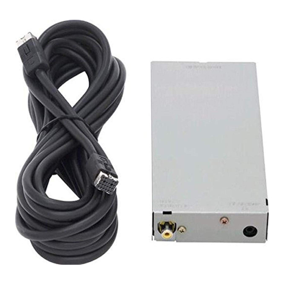
• Screw adjacent to mark on the product are used for disassembly. • For the applying amount of lobricants or glue, follow the instructions in this manual. (In the case of no amount instructions,apply as you think it appropriate.) 2.1 PACKING GEX-6100TV/UC... - Page 7 CEG1116 Antenna Unit CZX5019 6-2 Owner's Manual See Contrast table(2) 6-3 Warranty Card See Contrast table(2) (2) CONTRAST TABLE GEX-6100TV/UC and GEX-6100TVP/EW are constructed the same except for the following: Mark Symbol and Description GEX-6100TV/UC GEX-6100TVP/EW Owner's Manual CRD3641 CRD3657...
-
Page 8: Exterior
2.2 EXTERIOR GEX-6100TV/UC... - Page 9 CKN1032 Jack(CN2153) CKN1032 Screw ISS26P055FUC Front End(FE2201) See Contrast table(2) Pin Jack(CN2703) CKS1825 (2) CONTRAST TABLE GEX-6100TV/UC and GEX-6100TVP/EW are constructed the same except for the following: Mark Symbol and Description GEX-6100TV/UC GEX-6100TVP/EW Tuner Unit CWM8251 CWM8249 Front End(FE2201) CWB1093...
-
Page 10: Block Diagram And Schematic Diagram
3. BLOCK DIAGRAM AND SCHEMATIC DIAGRAM 3.1 BLOCK DIAGRAM - GEX-6100TV/UC TV TUNER PCB TV30V REG. TV5V REG. Q2601 IC 2651 TV9V TV30V TV9V TV5V TK11819M 75Ω DRIVE DIVER VIDEO Q2455 IC 2751 CN2703 NJM2267V CN2150 CN2701 ANT1 VIF DET... - Page 11 LA2120M TV5V Q2354 BRSBGI L2301 X2351 Q2352 22.70MHz Q2355 IFIN DETIN IFOUT AFOUT Q2357 IC 2352 SMETER Q2358 SIF(2ND)DET TC7SH02FU IC 2301 LA1145M X2352 Q2356 MULEV SDSEN 22.20MHz Q2359 Q2361 Q2362 VR2301 VR2302 BRSDK X2353 Q2360 21.70MHz CONNECTOR PCB GEX-6100TV/UC...
-
Page 12: Overall Connection Diagram(Guide Page)(Gex-6100Tv/Uc)
3.2 OVERALL CONNECTION DIAGRAM(GUIDE PAGE)(GEX-6100TV/UC) Note: When ordering service parts, be sure to refer to " EXPLODED VIEWS AND PARTS LIST" or "ELECTRICAL PARTS LIST". Large size SCH diagram CN2150 NOTE : Symbol indicates a resistor. Guide page Decimal points for resistor... - Page 13 TV TUNER PCB CONNECTOR PCB CN2701 CN2704 CN2701 CN2705 to AVR-W6100 series COMPOSITE VIDEO SIGNAL MONAURAL AUDIO SIGNAL(TV AUDIO) RF SIGNAL VIDEO IF SIGNAL AUDIO IF SIGNAL IF SIGNAL CN2703 TUNER UNIT Consists of TV TUNER PCB CONNECTOR PCB GEX-6100TV/UC...
- Page 14 A-b B GEX-6100TV/UC...
- Page 15 GEX-6100TV/UC...
- Page 16 CN2704 A-b B GEX-6100TV/UC...
- Page 17 GEX-6100TV/UC...
-
Page 18: Overall Connection Diagram(Guide Page)(Gex-6100Tvp/Ew)
The > mark found on some component parts indicates the importance of the safety factor of the part. Therefore, when replacing, be sure to use parts of identical designation. COMPOSITE VIDEO MONAURAL AUDIO RF SIGNAL VIDEO IF SIGNAL AUDIO IF SIGNAL IF SIGNAL GEX-6100TV/UC... - Page 19 TV TUNER PCB CONNECTOR PCB CN2701 CN2704 CN2701 CN2705 to AVR-W6100 series COMPOSITE VIDEO SIGNAL MONAURAL AUDIO SIGNAL(TV AUDIO) RF SIGNAL VIDEO IF SIGNAL AUDIO IF SIGNAL IF SIGNAL CN2703 TUNER UNIT Consists of TV TUNER PCB CONNECTOR PCB GEX-6100TV/UC...
- Page 20 A-b B GEX-6100TV/UC...
- Page 21 GEX-6100TV/UC...
- Page 22 CN2704 A-b B GEX-6100TV/UC...
- Page 23 GEX-6100TV/UC...
-
Page 24: Pcb Connection Diagram
For further information for respective destinations, be sure to check with the schematic dia- gram. 2. Viewpoint of PCB diagrams TC2110 Capacitor Connector SIDE A SIDE B P.C.Board Chip Part L2402 CN2704 L2301 GEX-6100TV/UC... - Page 25 SIDE B TV TUNER PCB VDIV5V VIDEO TVMONO GEX-6100TV/UC...
-
Page 26: Connector Pcb
4.2 CONNECTOR PCB SIDE A CONNECTOR PCB to AVR-W6100 series CN2701 SIDE B CONNECTOR PCB GEX-6100TV/UC... -
Page 27: Electrical Parts List
LCYB15NJ1608 R 2204 RS1/16S681J R 2205 RS1/16S101J L 2201 Inductor CTF1470 L 2202 Inductor LCTA2R2J2520 R 2206 RS1/16S102J L 2203 Inductor LCTA2R2J2520 R 2207 RS1/16S102J L 2204 Inductor CTF1470 R 2208 RS1/16S102J L 2205 Inductor LCTC1R5K2125 R 2209 RS1/16S102J GEX-6100TV/UC... - Page 28 C 2381 CKSRYB103K50 R 2511 RS1/16S471J C 2382 CKSRYB102K50 R 2512 RS1/16S821J C 2385 CCSRCK2R0C50 R 2601 RS1/16S102J C 2389 CCSRCH101J50 R 2651 RS1/16S101J C 2403 CEV470M16 R 2652 RS1/16S102J C 2404 CKSRYB103K50 R 2704 RS1/16S0R0J C 2405 CKSRYB224K16 GEX-6100TV/UC...
- Page 29 IC 2352 TC7SH02FU IC 2401 TA1290FN L 2401 Inductor LCTA2R2J2520 IC 2501 LA2120M L 2402 Coil CTE1149 IC 2651 TK11819M L 2451 Inductor LCTA6R8J2520 L 2452 Inductor LCKA150J2520 IC 2751 NJM2267V L 2453 Inductor LCKA150J2520 Q 2156 Transistor 2SC4226 GEX-6100TV/UC...
- Page 30 R 2702 RS1/16S101J R 2352 RS1/16S273J R 2354 RS1/16S221J R 2704 RS1/16S0R0J R 2751 RS1/16S105J R 2355 RS1/16S332J R 2752 RS1/16S105J R 2753 RS1/10S750J R 2356 RS1/16S102J R 2357 RS1/16S333J R 2754 RS1/10S750J R 2358 RS1/16S683J R 2360 RS1/16S681J GEX-6100TV/UC...
- Page 31 C 2365 CCSRCH100D50 C 2756 CEV101M16 C 2366 CCSRCKR50C50 C 2758 CEV220M16 C 2368 CKSRYB104K16 C 2759 CEV101M16 C 2369 CKSRYB104K16 C 2370 CKSRYB103K50 C 2371 CCSRCH101J50 C 2372 CCSRCH121J50 C 2373 CCSRCH7R0D50 C 2374 CCSRCKR50C50 C 2376 CKSRYB103K50 GEX-6100TV/UC...
-
Page 32: Adjustment
6. ADJUSTMENT - Adjustment Point L2402 VR2401 VR2751 VR2302 VR2301 L2301 VR2303 - Test Point VIDEO TVMONO GEX-6100TV/UC... - Page 33 GEX-6100TV/UC...
- Page 34 GEX-6100TV/UC...
-
Page 35: General Information
Disconnect the connector and then remove the Connector PCB. Removing the TV Tuner PCB (Fig.2) Straight the tabs at two locations indicated. Remove the two screws. TV Tuner PCB Disconnect the connector and then remove the TV Tuner PCB. Fig.2 GEX-6100TV/UC... -
Page 36: Connector Function Description
1. SDA 11. GVDTV 2. GND75 12. GNDV 3. BRSDK 13. NC 4. BRSGI 14. SL 5. GNDTV 15. TV9V 6. TVV 16. TVR 7. SCL 17. NC 8. NC 18. SD 9. TVARI 19. TVL 10. TV9V 20. GNDA GEX-6100TV/UC... - Page 37 2nd IF 1st IF LIMITER AMPLIFIER IF AGC DETECTION IC's marked by * are MOS type. *TC7SH02FU(GEX-6100TVP/EW) Be careful in handling them because they are very liable to be damaged by electrostatic induction. IN B IN A OUT Y GEX-6100TV/UC...
- Page 38 - Front End(FE2201:CWB1093)(GEX-6100TV/UC) Front End(FE2201:CWB1094)(GEX-6100TVP/EW) OSCILLATOR, MIXER GEX-6100TV/UC...
-
Page 39: Operations
8. OPERATIONS Basic Operation When using with a Pioneer Over Head Display AVR-W6100, please read the Over Head display’s Owner’s Manual. Basic Operation of TV Tuner 1. Select the TV source on the Over Head Display. For details, refer to the connected unit’s manual. - Page 40 • To select channels with the AVR-W6100’s main unit, first switch the selection mode to MANUAL/SEEK. Each time you simultaneously press the 2/3 CH button, the mode switches between MANUAL/SEEK and PRESET. Next, switch channels with a CH button. 4. Turn off the system. GEX-6100TV/UC...
- Page 41 • To switch the BSSM ON, press the CH CALL button for 2 seconds. B S S M JUST A MOMENT PLEASE. Each press changes the Mode ... • To cancel the process, press the CH CALL button for 2 seconds again before memorization is complete. GEX-6100TV/UC...
- Page 42 1. Display a menu screen and select [PRESET CHANNEL SETTING] menu. (Refer to the connected unit’s manual.) 2. Choose [PRESET NO.]. C O U N T R Y S E T T I N G PRESET NO . 1 [ 2ch] GEX-6100TV/UC...
- Page 43 6. Select [OK]. C O U N T R Y S E T T I N G 7. Press the 2 2 /3 3 button to preset. C O U N T R Y S E T T I N G GEX-6100TV/UC...
- Page 44 • This product is not compatible with channels in France. • Broadcast channels and broadcast systems may vary from country to country. If reception is not possible with the appropriate country group listed above, try reception using another country group. GEX-6100TV/UC...
- Page 45 (12 V DC) terminal, do not ON/OFF. remove the cap. Do not connect this lead to power source terminals to which power is continuously supplied. If the lead is connected to such terminals, the battery may be drained. Element GEX-6100TV/UC...