
Related Manuals for Acer AT1921


Summary of Contents for Acer AT1921
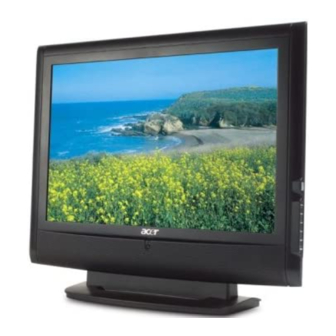
- Page 1 Acer AT1921/22 Service Guide Service guide files and updates are available on the CSD web: for more information, Please refer to http://csd.acer.com.tw/ 100% Recycled Paper - 1 -...
- Page 2 Copyright Copyright © 2003 by Acer Incorporated. All rights reserved. No part of this publication may be reproduced, transmitted, transcribed, stored in a retrieval system, or translated into any language or computer language, in any form or by any means, electronic, mechanical, magnetic, optical, chemical, manual or otherwise, without the prior written permission of Acer Incorporated.
- Page 3 Conventions The following conventions are used in this manual: Screen messages Denotes actual messages that appear on screen Note Gives bits and pieces of additional information related to the current topic. Warning Alerts you to any damage that might result from doing or not doing specific actions.
- Page 4 DIFFERENT part number code to those given in the FRU list of this printed Service Guide. You MUST use the list provided by your regional Acer office to order FRU parts for repair and Service of customer machines.
- Page 5 WARNING: (FOR FCC CERTIFIED MODELS) NOTE: this equipment has been tested and found to comply with the limits for a Class B digital device, pursuant to Part 15 of the FCC Rules. These limits are designed to provide reasonable protection against harmful interference in a residential installation.
- Page 6 PRECAUTIONS Do not use the monitor near water, e.g. near a bathtub, washbowl, kitchen sink, laundry tub, Swimming pool or in a wet basement. Do not place the monitor on an unstable trolley, stand, or table. If the monitor falls, it can injure a person and cause serious damage to the appliance.
-
Page 7: Special Notes On Lcd Monitors
SPECIAL NOTES ON LCD MONITORS The following symptoms are normal with LCD monitor and do not indicate a problem. NOTES Due to the nature of the fluorescent light, the screen may flicker during initial use. Turn off the Power Switch and then turn it on again to make sure the flicker disappears. You may find slightly uneven brightness in the screen depending on the desktop pattern you use. - Page 8 Table of contents Chapter 1 LCD TV FEATURE………………………………………………………………………..9 Chapter 2 OPERATING INSTRUTION ………………………………………………………..20 Chapter 3 MACHINE ASSEMBLY………………………………………………………………...25 Chapter 4 TROBLE SHOOTING…………………………………………………………………...39 Chapter 5 CONNECTOR INFORMATION…………………………………………………...42 Chapter 6 FRU LIST……………………………………………………………………………………...43 Chapter 7 SCHEMATIC DIAGRAM ……………………………………………………………..45 - 8 -...
-
Page 9: Chapter 1 Lcd Tv Feature
Chapter 1 LCD TV Feature Destination Europe Color System CCIR B/G, D/K, I and L/L’ Sound System Sound 1 and Sound 2 Stereo System NICAM and FM Stereo ( A2 ) Channel System Full frequency range from channel E2 ( 48.25 MHz ) to channel E69 ( 855.25 MHz) Sub-Title Teletext 100 pages... - Page 10 TV System PAL and SECAM system Receivable Tuner FQ1216-MK5 Horizontal input frequency range : 30~71 Vertical input frequency range : 50~85 Hz Maximum resolution : 1440*900 When input signal is out of range or down scaling support ,the OSD will show "Out of Range "within 5 seconds and LED Out of Range is green...
-
Page 11: Vesa
THD(Total Harmonic D distortion) Limited to 5 % at 2W (at 0.1~15 KHz) OSD Capability On screen display adjustment function ISP (In System Programming) function ISP Functions available for revising driver easily. Input Voltage 90 ~ 264 V , 47 ~ 63 Hz Input Current 0.6~1.5 A 58 Watts(not support Energy Star max... - Page 12 Impedance More than 22kΩ Interface 3.5mm Stereo Jack , Black color Type Stereo R/L Channels Level 40mW rms/per Channel(typ.) for 32 ohm earphone Impedance 32 ohm Headphone Output Interface 3.5mm Stereo Jack Max. Audio output 5W + 5W (at 1.0Vp-p / 1kHZ input,10% THD max.) Sound Distortion 1% THD max.
- Page 13 PC Timing Mode Pixel Hor. Freq. Hor. Vert. Vertical Freq. Standard Format Format (kHz) Polarity (Hz) Polarity 640*350 31.5 720*400 31.47 640*480 31.47 640*480 66.7 640*480 37.861 VESA 640*480 37.5 VESA 640*480 43.3 VESA 800*600 35.156 VESA 800*600 37.879 VESA 800*600 48.077 VESA...
-
Page 14: Lcd Panel
Monitor Block Diagram RS232 Speaker EEPROM PC Audio input CVBS/S-Video Audio input Audio Audio SCART Audio input Processor Amplifier MT8291 Tuner Audio input TFA9810 Tuner SCART Audio output 2-Wire Bus Earphone Video EEPROM SPDIF I2S Bus S-video 2-Wire Bus Backlight PC Video input CVBS input S-Video input... - Page 15 PCB CONDUCTOR VIEW MAIN BOARD...
- Page 17 BUTTON BOARD...
- Page 18 USB BOARD...
- Page 19 POWER BOARD...
-
Page 20: Operating Instructions
Chapter 2 OPERATING INSTRUCTIONS Front Panel Definition This Section defines the front panel User Interface for Led Indictor and Key function. BUTTON OSD On OSD Off 1 Power Software On / Off Menu / Press this button to open the OSD or Enter Exit function CH Up... - Page 21 Number key 2 Number key 3 Number key 4 Number key 5 Number key 6 Number key 7 Number key 8 Number key 9 Number key 0 Recall Reture to previous channel Enter Enter to confirm channel selection by number key 1.Navigate up in the OSD menu 2.channel up when OSD menu is not showed on screen Down...
- Page 22 SIZE When in teletext pages, this key zoom page toggle 1X/2X and page selection by Up-arrow and Down-arrow SUBPAGE Subpage directly HOLD when in teletext pages, press this button temporarily holds the current teletext page Red color button to do teletext operation In teletext mode, Green color button to teletext operation In teletext mode Yellow color button to teletext operation In teletext mode 42 B...
- Page 23 Sound Effect [Off] Steady Sound [Off] Country France Germany Italy Spain Switzerland Denmark Belgium Netherlands Luxembourg Czech Republic Portugal United Arab Emirates Saudi Arabia Skip [Off] Reorder Name Frequency Auto Scan Scan up Scan down Manual Scan Scan for update Lock This Please enter your PIN Lock/[Unlock]...
-
Page 24: Teletext Operation
Dansk Dutch Sleep [Off]/15/30/45/60/90/120 Please enter your PIN New PIN: Type it again to Set PIN [- - - -] confirm: Full [16:9] Panorama Letterbox1 Wide Mode Letterbox2 HDMI Scan Info. [Auto] / Overscan / Underscan Factory Default Teletext Operation TELETEXT/MIX TV/Teletext Mode By pressing Teletext (go to index page),screen will change from TV/AV mode to... -
Page 25: Chapter 3 Machine Assembly
Chapter 3 Machine assembly This chapter contains step-by-step procedures on how to assemble the monitor for maintenance and trouble shooting NOTE: 1. The screws for the different components vary in size. During the disassembly process, group the screws with the corresponding to avoid mismatch when putting back the components. 2. - Page 26 Real View: Top View: - 26 -...
- Page 27 Side View: (unit: mm )
- Page 28 Assembly process CHECKING THE FOAM AND PUT IT TO THE PRODUCTION LINE. CHECKING THE SHIELDING AND STICK 2*PCS FOAM. PUT THE FLOW CARD TO THE BOARD. SCAN THE FLOW CARD AND CODE OF P/B INTO THE TMS SYSTEM. INSERT THE JUMP CABLE INTO THE P/B AS LEFT SHOW.
- Page 29 LOCK UP 4*PCS SCREWS(F3.0*6.0- T) TO THE LOCATION OF M/B AND P/B AS LEFT SHOW. LOCK UP 1*PCS SCREW(F4.0*8.0-T) TO THE P/B. LOCK UP 1*PCS SCREW(M3.0*5.0-I) TO THE P/B. LOCK UP 2*PCS SCREWS(F3.0*6.0- T) TO THE P/B AS LEFT SHOW. LOCK UP 1*PCS SCREW(M3.0*5.0) TO THE SHIELDING .
- Page 30 TEAR OFF THE PROTECT FILM OF PANEL AND CHECKING IF BAD. STICK GOOEY TAPE FOR FIXING PROTECT FILM. TURN OVER LCD AND TEAR OFF EP BAG. STICK 1*PCS CODE TO PANEL AS LEFT SHOW. SCAN THE FLOW CARD, PANEL CODE AND P/N TO TMS SYSTEM.
- Page 31 STICK 1*PCS CABLE FASTNER TO THE DOWNSIDE OF RIGHT BRACKET AS LEFT SHOW. PUT THE RIGHT BRACKET TO THE PAENL. LOCK UP 2*PCS SCREWS TO RIGHT BRACKET FOR FIXING. SCAN FLOW CARD AND M/B CODE TO THE TMS SYSTEM. INSERT THE LVDS CABLE TO THE JOINT OF PANEL.
- Page 32 CONNECT THE SHIELDING AND BRACKET AS LEFT SHOW. LOCK UP 4*PCS SCREWS(F3*6) FOR FIXING SHIELDING. TRUN OVER LCD. CHECKING THE BEZEL IF BAD AND PUT IT TO THE PANEL. TRUN OVER THE LCD.
- Page 33 LOCK UP 3*PCS SCREWS FOR FIXING RIGHTSIDE BEZEL AND BRACKET. LOCK UP 3*PCS SCREWS FOR FIXING LEFTSIDE BEZEL AND BRACKET. INSERT THE 4PCS LAMP CABLE TO PUT THE SPEAKER TO THE BEZEL AS LEFT SHOW. LOCK UP 4*PCS SCREWS FOR FIXING LEFT SPEAKER.
- Page 34 LOCK UP 4*PCS SCREWS FOR FIXING RIGHT SPEAKER. GET THE B/B AND CONNECT THE B/B AND BEZEL WITH B/B CABLE. GET THE IR/B AND INSERT THE IR/B CABLE TO THE JOINT OF M/B. PUT THE IR/B TO THE LOCATION OF BEZEL.
- Page 35 LOCK UP 2*PCS IO NUTS FOR FIXING SHIELDING. INSERT 1*PCS CABLE FASTNER TO SHIELDING. SETTLE THE CABLE FOR B/B, SPEAKER, IR AND INSERT THEM INTO THE JOINT AS LEFT SHOW. STICK 1*PCS ACETIC TAPE FOR FIXING B/B AS LEFT SHOW.
- Page 36 STICK 1*PCS AL FOIL TO AL1 WHICH IS BETWEEN THE PAENL AND SHIELDING. LOCK UP 2*PCS SCREWS TO FIXING FASTENER BETWEEN PAENL AND BEZEL. CHECKING THE CABLE IF WRONG WAY. CHECKING THE SCERWS IF LOOSE. CHECKING THE AL FOIL IF WRONG WAY.
- Page 37 LOCK UP 2*PCS SCREWS FOR FIXING REAR COVER STICK 1*PCS FLOW CARD TO GOOEY OF REAR COVER. COVER IT WITH BAG. LOCK UP 5*PCS SCREWS FOR FIXING REAR COVER AND BEZEL. INSERT THE VGA CABLE INTO THE JOINT OF VGA. CONNECT THE POWER CORD AND LCD TV.
- Page 38 STICK FLOW CARD TO BASE. CHECKING THE BEZEL WHETHER BAD. CHECKING THE REAR COVER WHETHER BAD. CHECKING FUNCTION/B WHETHER BAD.
-
Page 39: Trouble Shooting
Chapter 4 TROUBLE SHOOTING This chapter provides trouble shooting information for AT1921/22 NO POWER Check P/B CN101 pin7 12V, Separate M/B & P/B Check CN101 Change P/B pin15V Correct? pin7 12V, pin15V Correct? Check M/B L56 3.3V L58 1.8V Change M/B... - Page 40 No Characters , Missing Color Check M/B CN3 Change Pin28~30 5V correct? Change Check LVDS cable LVDS cable Check LCD panel VGA always show No Signal Check VGA cable Change correct? VGA cable Check input P2 Change Pin13 H-sync ,pin14 V-sync correct? Check PC...
- Page 41 Video-mode always show No Signal Check Video cable Change correct? Video cable Change I/O board...
- Page 42 Chapter 5 Connector Information Length: 1.8meters +15mm/-0mm Cable Color: Black color Power Cord Quantity: Length: 1.8meters +15mm/-0mm Cable Color: Black color AV (Video& Audio) Cable Quantity: Length: 1.8meters +15mm/-0mm Cable Color: Black color SCART Cable Quantity: Length: 2.5meters +15mm/-0mm Cable Color: Transparent color TV Antenna Cable Quantity:...
-
Page 43: Chapter 6 Fru List
Acer office to order FRU parts repair and service of customer machines. NOTE: To scrap or to return the defective parts, you should follow the local government ordinance or regulations on how best to dispose it, or follow the rules set by your regional Acer office on how to return it. -
Page 45: Chapter 7 Schematic Diagram
Chapter 7 SCHEMATIC DIAGRAM AT1920 M/B CONTENTS SCHEMATIC SHEET CONTENT INDEX & POWER CONNECTOR MT8201 LQFP256 E-PAD DDR & FLASH HDMI INPUT-MT8293 VGA IN & PC AUDIO IN TUNER INPUT / GPIO AV/SV/AUDIO SCART FULL FUNCTION MT8291 AUDIO ADC LVDS OUT AUDIO AMP Keypad IR... - Page 46 DV33B DV33B 5VSB +12V_IN +12V +5V_IN 5VSB 10k/6 1k/6 10k/6 R290 10k/6 10k/6/NC C195 C196 C197 SI9435 SI9435 2200pF/6 0.1uF/6 10uF/25V BL_ON/OFF SI9435/NC 2200pF/6 0.1uF/6 10uF/25V 0.1uF/6/NC 10uF/25V/NC 2200pF/6/NC R291 SB33B 2.2K/6 2.2K/6/NC PWM1 PWM1 2N3904 2.2K/6 SOT23 4.7k/6 R308 10k/6/NC R354 4.7k/6...
- Page 47 STANDBY ANALOG POWER 2.2K/6F 1.4K/6F 2.2K/6F 5.6k/6F ASB18A SB18A ASB18A XTALVDD SB33B SB33A Bead_121_4A/8 5VSB Bead_121_4A/8 Bead_121_4A/8 Bead_121_4A/8 0.1uF/6 VOUT VOUT LVDS_GND ADJ/GND ADJ/GND Bead_121_4A/8 PLLVDD AP1117ELA/TO252 0.1uF/6 AP1117ELA/TO252 0.1uF/6 0.1uF/6 10uF/25V 0.1uF/6 10uF/25V 10uF/25V 0.1uF/6 10uF/25V 0.1uF/6 LVDS_GND Power ON alive source NORMAL VIDEO DAC POWER ADCV33A 2.2K/6F...
- Page 48 SOY1 SOY1 Y 1 N PB1P PB1P PB1N PB1N PR1P PR1P PR1N PR1N S C1 S C0 CVBS2 CVBS2 CVBS0 CVBS0 CVBS1 CVBS1 MPX1 VG AVSYNC# VGAVSYNC# MPX1 VGAHS YNC# VGAHSYNC# SCART_FB SCART_FB GPIO7_LRCK GPIO7_LRCK GPIO8_BCKL GPIO8_BCLK GPIO9_MCLK GPIO9_MCLK 7,14 AOSDATA3 AOSDATA3 VI[0..15]...
- Page 49 D1V25 DV25B DV25B 22R/8P4R RN13 75R/8P4R A_RA0 D_RA0 D_RA0 A_RA1 D_RA1 D_RA1 A_RA2 D_RA2 D_RA2 F_A1 F_D0 A_RA3 D_RA3 D_RA3 F_A2 F_D1 D_DQ0 D_DQ15 DQ15 F_A3 F_D2 VDDQ VSSQ 22R/8P4R RN14 75R/8P4R F_A4 F_D3 D_DQ1 D_DQ14 DQ14 A_RA7 D_RA7 D_RA7 F_A5 F_D4 D_DQ2...
- Page 50 R294 100/6F R295 200R/6F AVCC DV33B HDMI_PLUGPWR VCC18 DV33B VCC18 CB47 CB48 CB49 CB50 CB51 CB52 CB53 R332 R333 VOUT Bead_121_4A/8 10k/6 10k/6 R341 R340 R343 R344 1000pF/6 0.1uF/6 0.1uF/6 0.1uF/6 0.1uF/6 0.1uF/6 0.1uF/6 0.1uF/6 1000pF/6 4.7k/6 4.7k/6 4.7k/6/NC 4.7k/6/NC ADJ/GND CB54 R324...
- Page 51 VGA_PLAG VGA IN 10k/6 0.01uF/6 FB/6 68R/6 SDA0 SDA0 0R/6/NC VGASDA 100R/6 D-SUB15 DCN15VGA-15P 75R/6F 5pF/6 RE D_GND EZJZ0V800AA/NC EZJZ0V800AA/NC 0.01uF/6 RE D_GND GRN_GND 100R/6 VGASDA_IN GREEN VGA_PLUGPWR BLU_GND HS YNC# BLUE VGA_PLUGPWR VSY NC# VGASCL_IN 4.7nF/6 0R/6 VGASOG VGASOG VGA_PLAG GREEN FB/6...
- Page 52 +5Vt FQ1216ME Bead_121_4A/8 VS_TUNER R155 10k/6 10uH RC1206 CB71 CE12 CE13 TU_SDA 2,4,6,11 3300pF/6 0.1uF/6 1uF/6 330uF/25V 330uF/25V 2N7002 N-MOSFET DV33A VS_IF R156 10k/6 10uH RC1206 CB72 CE14 3300pF/6 0.1uF/6 1uF/6 330uF/25V TU_SCL 2,4,6,11 R329 100R/6 TU_SDA R330 100R/6 TU_SCL 2N7002 N-MOSFET DV33A...
- Page 53 S-VIDEO +RCA TEKCON_RCAJACK-SJACK 0R/6 R157 47nF/6 SY0_IN AV_SY0 AVSVL AV0_IN 0R/6 R158 75R/6F 330pF/6 AV0_GND EZJZ0V800AA/NC SC0_IN 330pF/6 330pF/6 SY0_GND SY0_IN AVSVR SY0_GND 0R/6 SC0_GND 0R/6 R159 47nF/6 SC0_IN AV_SC0 0R/6 R160 0R/6 75R/6F 330pF/6 AVSVL EZJZ0V800AA/NC AV0SY0_L 330pF/6 330pF/6 SC0_GND R401 C100...
- Page 54 SCART_FB SCART_FB C107 SCT1_FS_IN R181 33k/6 ADC_IN0 ADC_IN0 4.7nF/6 R163 0R/6 SO Y1 SOY1 R184 R183 EZJZ0V800AA/NC 75R/6F EZJZ0V800AA/NC 10k/6 C108 0R/6 47nF/6 SCT1_AV_IN R165 18R/6 SCT1_CVBS S Y0 CVBS2 C109 C110 R167 C111 330pF/6 EZJZ0V800AA/NC 56R/6 SCART PIN8 VIDEO STATUS SCART PIN16 RGB STATUS 330pF/6/NC 330pF/6/NC...
- Page 55 DV33B CE20 10uF/25V R187 34.5K/6 SCT1_AUR_IN Bead_121_4A/8 DV DD VMIDDAC VMIDADC DVDD CE21 10uF/25V R188 34.5K/6 RC0805 C130 SCT1_AUL_IN C129 CB74 CB75 10uF/10V/8 CB76 CE23 10uF/25V R189 34.5K/6 CB111 CE22 CE24 VGAIN_R 10uF/10V/8 0.1uF/6 100uF/16V 0.1uF/6 CC0805 CC0603 CE25 10uF/25V R190 34.5K/6 33uF/25v...
- Page 56 LOCATION LVDS VCC +12V +12V Bead_121_4A/8 DV33A DV33A Bead_121_4A/8/NC PANEL_PW R236 0R/6/NC CLK1N CLK1P CE39 CE40 R238 R237 330uF/25V 330uF/25V LVDSVDD CE41 330uF/25V 10k/6/NC 10k/6/NC CAR315 CLK2N CLK2P R241 C246 CE42 330uF/25V CB90 CB91 100k/6 0.1uF/6 0.1uF/6 0.1uF/6 SI9435 R240 R239 1841-30P DV33A...
- Page 57 +12V_AMP +12VAUDIO +12V_AMP R245 MAX809-S SOT-23 2.93V RST/NC DV33A 10k/6 ENABLE SOT23 +12V_AMP Bead_121_4A/8 R298 C146 CE43 0.1uF/6 100uF/16V R412 2N3904/NC 2N3904 R299 4.7k/6/NC 1k/6/NC 10k/6 OFF_MUTE R246 10k/6 GPIO20 LL4148/NC R247 10k/6 ENABLE Reset circuit +12VAUDIO 2,11 +12V_AMP R248 Bead_121_4A/8 Bead_121_4A/8 10R/12...
- Page 58 SB33B MTK ADC 0V~2.8V SB33B 0.22V 0.58V 1.1V 1.59V R276 MENU R275 2.2V 10k/6 SOURCE 2.49V 6.8k/6 PW_KEY R277 R278 R279 R280 R281 R282 C186 R391 ADC_IN1 20pF/6 510R/6 1k/6 2k/6 3k/6 6k/6 9.1k/6 47K/6/NC C193 C192 C191 C190 C188 C187 CB92 0.1uF/6...
-
Page 59: Number Key
TOUCH SWITCH 4P MENU TOUCH SWITCH 4P AUTO TOUCH SWITCH 4P POWER JST 8Pin PH2.0mm H TOUCH SWITCH 4P Down TOUCH SWITCH 4P TOUCH SWITCH 4P RIGHT TOUCH SWITCH 4P LEFT PROJECT : AT1922 Title 01. Contents Size Document Number R e v S9Q-WN B/B Key Board... - Page 60 4501-04-05P-R green LED1 orange EL-209-2EGW MTH276D126 MTH276D126 SEN1 PROJECT : AT1922 Title Size Document Number R e v IR-BOARD Date: Tuesday, May 29, 2007 Sheet...