
Related Manuals for Jaycar Electronics QC3624

Summary of Contents for Jaycar Electronics QC3624
- Page 1 Wireless Video Door Phone Installation and Operating Instructions Model: QC3624 PLEASE READ THESE INSTRUCTIONS CAREFULLY BEFORE USING THIS PRODUCT AND KEEP THIS MANUAL FOR FUTURE REFERENCE.
-
Page 2: Table Of Contents
INTRODUCTION ....................2 IMPORTANT SAFETY PRECAUTIONS ..............2 KNOWING YOUR DEVICES ................3 DOOR UNIT ......................3 ANSWERING UNIT ....................KNOWING THE SCREEN ICONS ................5 MOUNTING THE DOOR UNIT .................. KNOWING THE MAIN MENU ................. 10 ADVANCED SETTINGS ................. 11 CAMERA SETUP ....................11 RECORDER SETUP ....................12 SETUP MASKING AREA ...................14 EVENT LIST ......................15... -
Page 3: Introduction
INTRODUCTION PLEASE READ BEFORE YOU START Always use discretion when installing CCTV equipment, especially when there is perceived policy. Enquire relevant local regulations applicable to the lawful installation of video recording/ surveillance. Third party consent may be required. WIRELESS DEVICES OPERATING RANGE Ensure the signal reception viewed from the wireless camera(s) is the best possible reception between the camera(s) and the Wi-Fi router. -
Page 4: Knowing Your Devices
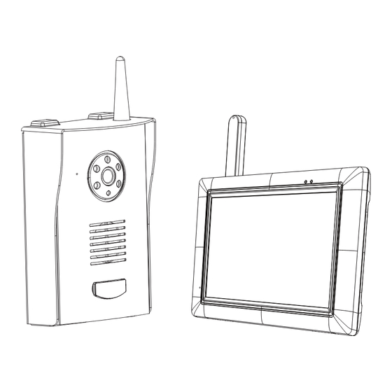
KNOWING YOUR DEVICES DOOR UNIT Item Function Item Function Antenna Dry Contact Output A Speaker Dry Contact Input (for DC Power Cable) IR LED Dry Contact Output B Power Adaptor Call Button DC Power Cable Microphone Unlock Connection Cable Pairing Key Battery Compartment Note: 1. -
Page 5: Answering Unit
ANSWERING UNIT Item Function Item Function Wirelless Signal Indicator Flip-out Stand Power Indicator Micro SD Slot Microphone Reset Antenna AV Out Jack Power Button Adaptor Plug Speaker Note: When using A/V cable connecting the receiver to TV, the display on receiver will not be available and answering visitor function will also be turned off until disconnecting A/V cable from the receiver. -
Page 6: Knowing The Screen Icons
KNOWING THE SCREEN ICONS Item Function Channel Number Active Voice Channel Wireless Signal Strength Camera Battery Capacity Channel Status Recording Countdown Indicator Receiver Battery Status System Time Information Record Status... - Page 7 System Tray Icon Icon image Name Function System Tray System Tray-Hide & display tray icon Channel Display Press to switch display channel Two Way Audio Press to start/stop communication. Door Control Press to open the door (Dry Contact B) Gate Control Press to open the gate (Dry Contact A) Volume Press to adjust receiver volume...
-
Page 8: Mounting The Door Unit
MOUNTING THE DOOR UNIT BEFORE YOU START • Before installing the door unit, please first check to make sure the location is suitable for the installation. To avoid possible damages, the installation location should free from excessive moisture, dust • and vibration. - Page 9 INSTALLATION VIA DC POWER MODE Dry Contact A - Related icon Adaptor connect to DC Jack Dry Contact B - Related icon Input A. 4-Wire Type Connection Diagram Power Power B. 2-Wire Type Connection Diagram 1. Remove the back cover of door unit. 2.
- Page 10 MOUNTING THE THE ANSWERING UNIT 1. Connect the power adapter to the DCIN jack and the nearest wall outlet. 2. Press [Power Button] for two seconds to turn on the receiver. Note: When using A/V cable connecting the receiver to TV, the display on receiver will not be available and answering visitor function will also be turned off until disconnecting A/V cable from the receiver.
-
Page 11: Knowing The Main Menu
KNOWING THE MAIN MENU Item Function CAMERA SETUP RECORDER SETUP EVENT LIST SYSTEM SETUP ALARM BUZZER PAN TILT ZOOM SCAN ACTIVATED CAMERAS MEMORY CARD OVERWRITE RETURN TO LIVE VIEW... -
Page 12: Advanced Settings
ADVANCED SETTINGS CAMERA SETUP In this section you can pair and adjust the brightness setting for Item Function door unit and optional CCTV cameras (for more information on CH1 (Doorphone 1) where to purchase the additional CCTV camera please contact vendor). -
Page 13: Recorder Setup
RECORDER SETUP 1. Each motion recording time is 2 minutes. 3. Users can stop manual record by themselves. Recording will be stopped after 10 minutes if users do not stop it. Item Function Memory Card Erase Record Schedule (24 hours) - Tap to start for matting - M = Motion Setup Masking Area... -
Page 15: Setup Masking Area
SETUP MASKING AREA 1. Save & Exit 2. Block grid 3. Unblock grid... -
Page 16: Event List
EVENT LIST DATE 1. Previous Page 2. Next Page 3. Return 4. Folder (Date) - Page 17 Press folder and hold on 2 seconds 5. Delete 6. Cancel Date Folder...
-
Page 18: Time
TIME 1. Return 2. Folder (Time) Press folder and hold on 2 seconds 3. Delete 4. Cancel... - Page 19 File 5. Previous Page 8. File 6. Next Page 9. Delete 7. Return 10. Cancel...
-
Page 20: File
FILE 1. Tray Icon Expand/Hide 2. Backward 3. Pause/Play 4. Forward 5. Display Channel 6. Stop Playback and Back to Folder 7. Time Stamp Information 8. Channel Status 9. Play Status... -
Page 21: System Setup
SYSTEM SETUP Item Description Multi Channels Idle Display - QUAD Display Date and Time - Doorphone Display - Adjust Year/Month/Date/Hour/ - 10 Sec. Scan with Doorphone Display Minute - 10 Sec. Scan without Doorphone Display TV Output Default (Language Setting) - NTSC/PAL - English (Default) Power Saving... - Page 22 TV Output Tip: Users should choose right TV output format to match NTSC or PAL TV. Receiver output will be invisible when TV output port is connected. Power Saving Tip: Set receiver panel turn off time to save the power. Multi Channels Idle Display Tip: Set sequential switch time interval of all active channels.
-
Page 23: Alarm Buzzer
ALARM BUZZER Alarm Buzzer setting of receiver. -
Page 24: Pan Tilt Zoom
PAN TILT ZOOM 1. Channel Information 2. Digital Zoom Information (2X) 3. Zoom Mode Status 4. Wireless Signal Strength 5. Receiver Battery Status 6. System Time Information Note: 1. Red triangle mark is used to adjust the visible range. 2. Black return mark is used to exit the mode. -
Page 25: Scan Activated Cameras
SCAN ACTIVATED CAMERAS Enter sequential switch mode of all active channels. System Tray Icon 1. Channel Information 2. Scan Activated Cameras Mode 3. Wireless Signal Strength 4. Receiver Battery Status 5. System Time Information 6. System Tray Icon 7.Exit Scan Mode and Back to Setup Menu... -
Page 26: Memory Card Overwrite
MEMORY CARD OVERWRITE... -
Page 27: Pc Playback Software
PC PLAYBACK SOFTWARE Sec24 MEDIA PLAYER INTRODUCTION The Sec24 Media Player is specially designed for security playback the unique video format generated from the system after detecting unusual movements from the site where the camera of the system is installed. 1. -
Page 28: Software Installation
Software Installation Insert the CD into the CD-ROM of the PC. Click on MY COMPUTER, double click on the drive where the CD-ROM is assigned by the PC (for example: E;\) and you will find the Sec24 Media Player icon. Please read the following steps to complete installation. - Page 29 Note: The following error message will appear if you did not select “Run as administrator” option first before starting the installation. 2. Double click the icon to start the installation process. 3. Click “Next” to continue the installation. 4. When the installation is completed, click “Finish” to exit the install wizard.
-
Page 30: Playback Recorded File(S)
Playback Recorded File(s) 1. Double click the Sec24 Media Player icon on the desktop to start the software. Sec24 Media Player icon 2. Click on “Load” to import and playback previous recorded files (SNX files) already stored on your PC. Note: You will first need to save the files from the Micro SD card to the PC first. - Page 31 Channel Disable / Enable Select During playback, all four channels can playback at once, including audio. For privacy concern, user can select specific channel(s) for playback, with or without audio. Select Audio to playback audio from channel 1 or 2 or 3 or 4 Select 1 to playback video image from channel 1 Select 2 to playback video image from channel 2 Select 3 to playback video image from channel 3...
-
Page 32: Adding Additional Cctv Camera
ADDING ADDITIONAL CCTV CAMERA CAMERA SETUP Note: A. Channel 1 is dedicated to door unit only. B. Only use camera specified compatibility. NOT all CCTV cameras will work with this system. For more details please contact your vendor. To add additional CCTV camera, first make sure the camera is powered Item Function on. -
Page 33: Product Specification
PRODUCT SPECIFICATION Door Unit Receiver Unit Maximum Unit(s) Communica on Range 200 Meters (Line of Sight) View Angle H: 90°±-3; V: 60°±-3 IR LED Wave Length 850nm Resolu on 640 x 480 (VGA) 800 x 480 (LCD) Single Channel 640 x 480 (VGA) Mul ple Channel 320 x 240 (QVGA) per Channel IR Night Vision Range 2 Meters...