Table of Contents
Advertisement
Quick Links
QQ
3 7 63 1515 0
FLASH MEMORY NAVIGATION AUDIO RECEIVER
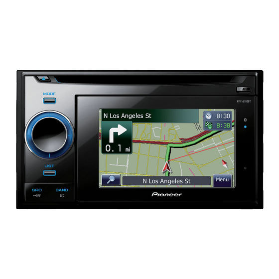
AVIC-U310BT
GPS NAVIGATION AUDIO SYSTEM
AVIC-F310BT
AVIC-F310BT
This service manual should be used together with the following manual(s):
TE
L 13942296513
Model No.
CX-3240
CRT4050
www
For details, refer to "Important Check Points for Good Servicing".
.
PIONEER CORPORATION
PIONEER ELECTRONICS (USA) INC. P.O. Box 1760, Long Beach, CA 90801-1760, U.S.A.
PIONEER EUROPE NV Haven 1087, Keetberglaan 1, 9120 Melsele, Belgium
PIONEER ELECTRONICS ASIACENTRE PTE. LTD. 253 Alexandra Road, #04-01, Singapore 159936
PIONEER CORPORATION 2009
http://www.xiaoyu163.com
Order No.
Mech. Module
S10.5COMP2-iPod/USB
x
ao
y
i
4-1, Meguro 1-chome, Meguro-ku, Tokyo 153-8654, Japan
http://www.xiaoyu163.com
8
AVIC-U310BT/XSUC
/XSEU5
/XSAU
Q Q
3
6 7
1 3
CD Mech. Module : Circuit Descriptions, Mech. Descriptions, Disassembly
u163
.
2 9
9 4
2 8
1 5
0 5
8
2 9
9 4
Remarks
m
co
K-ZZZ.-001 JUNE 2009 Printed in Japan
9 9
ORDER NO.
CRT4377
/XSUC
2 8
9 9
Advertisement
Table of Contents

Related Manuals for Pioneer


Summary of Contents for Pioneer
- Page 1 PIONEER CORPORATION 4-1, Meguro 1-chome, Meguro-ku, Tokyo 153-8654, Japan PIONEER ELECTRONICS (USA) INC. P.O. Box 1760, Long Beach, CA 90801-1760, U.S.A. PIONEER EUROPE NV Haven 1087, Keetberglaan 1, 9120 Melsele, Belgium PIONEER ELECTRONICS ASIACENTRE PTE. LTD. 253 Alexandra Road, #04-01, Singapore 159936 PIONEER CORPORATION 2009 K-ZZZ.-001 JUNE 2009 Printed in Japan...
-
Page 2: Safety Information
Improperly performed repairs can adversely affect the safety and reliability of the product and may void the warranty. If you are not qualified to perform the repair of this product properly and safely, you should not risk trying to do so and refer the repair to a qualified service technician. - Page 3 3 7 63 1515 0 WARNING! The AEL (accessible emission level )of the laser power output is less than CLASS 1 but the laser component is capable of emitting radiation exceeding the limit for CLASS 1. A specially instructed person should do servicing operation of the apparatus.
- Page 4 9 There should be no spark traces or similar marks on the power plug. When spark traces or similar marks are found on the power supply plug, please check the connection and advise on secure connections and suitable usage. Please exchange the power cord if necessary.
-
Page 5: Table Of Contents
6.3 USING THE TEST DISC ..........................38 7. DISASSEMBLY ...............................48 8. EACH SETTING AND ADJUSTMENT......................55 8.1 CD ADJUSTMENT ...........................55 8.2 CHECKING THE GRATING AFTER CHANGING THE PICKUP UNIT ............56 L 13942296513 8.3 TOUCH PANEL TEST MODE ........................58 9. EXPLODED VIEWS AND PARTS LIST ......................60 9.1 PACKING..............................60... -
Page 6: Service Precautions
Therefore, for lead-free soldering, the tip temperature of a soldering iron must be set to around 373 C in general, although the temperature depends on the heat capacity of the PC board on which reworking is required and the weight of the tip of the soldering iron. -
Page 7: Specifications
2. SPECIFICATIONS 3 7 63 1515 0 2.1 SPECIFICATIONS UC medel Backup current ....5 mA or less L 13942296513 u163 AVIC-U310BT/XSUC http://www.xiaoyu163.com... - Page 8 3 7 63 1515 0 L 13942296513 u163 AVIC-U310BT/XSUC http://www.xiaoyu163.com...
- Page 9 EU5 medel 3 7 63 1515 0 Backup current ....5 mA or less L 13942296513 u163 AVIC-U310BT/XSUC http://www.xiaoyu163.com...
- Page 10 3 7 63 1515 0 L 13942296513 u163 AVIC-U310BT/XSUC http://www.xiaoyu163.com...
- Page 11 AU medel 3 7 63 1515 0 Backup current ....5 mA or less L 13942296513 u163 AVIC-U310BT/XSUC http://www.xiaoyu163.com...
- Page 12 3 7 63 1515 0 L 13942296513 u163 AVIC-U310BT/XSUC http://www.xiaoyu163.com...
-
Page 13: Disc/Content Format
2.2 DISC/CONTENT FORMAT 3 7 63 1515 0 The Bluetooth word mark and logos are owned by the Bluetooth SIG, Inc. and any use of such marks by Pioneer Corporation is under license. Other trademarks and trade names are those of their respective owners. -
Page 14: Panel Facilities
2.3 PANEL FACILITIES 3 7 63 1515 0 L 13942296513 u163 AVIC-U310BT/XSUC http://www.xiaoyu163.com... - Page 15 3 7 63 1515 0 L 13942296513 u163 AVIC-U310BT/XSUC http://www.xiaoyu163.com...
-
Page 16: Connection Diagram
2.4 CONNECTION DIAGRAM 3 7 63 1515 0 Connection Diagram L 13942296513 u163 AVIC-U310BT/XSUC http://www.xiaoyu163.com... -
Page 17: Basic Items For Service
L 13942296513 See the table below for the items to be checked regarding video and audio: Item to be checked regarding video Item to be checked regarding audio Disturbed image (video jumpiness) -
Page 18: Pcb Locations
3.2 PCB LOCATIONS 3 7 63 1515 0 CD Core Unit (S10.5COMP2-iPod-C3) Key PCB GPS IF Unit Main PCB NAVI Board L 13942296513 Main Unit Consists of Main PCB Key PCB Unit Number CWN4078:AVIC-U310BT/XSUC Unit Number CWN4079:AVIC-F310BT/XSEU5 Unit Number... -
Page 19: Jigs List
CD Mechanism Module Grease GEM1045 CD Mechanism Module 3.4 CLEANING Before shipping out the product, be sure to clean the following portions by using the prescribed cleaning tools: Portions to be cleaned Cleaning tools u163 CD pickup lenses Cleaning liquid : GEM1004... -
Page 20: Block Diagram
4. BLOCK DIAGRAM 3 7 63 1515 0 4.1 OVERALL CONNECTION DIAGRAM Power Switch OTSW1 OTJ1 SSM120 AXA2R73061 RESET OTSW1 STS-A5 A:CX AVIC-U310BT/XSUC B:CX AVIC-F310BT/XSEU5 C:CX AVIC-F310BT/XSAU BT-ANT1 OSCAR150 GPS ANTENNA ASSY CXE2705-A GPJ2 FM/AM TUNER L 13942296513 CKS5702-A:K... - Page 21 3 7 63 1515 0 OTJ2 Touch Panel MB005S503ZRA OTJ1 AXA2R73061 PND UNIT LCJ2 FH23-45S-0.3SHW A:CXE2187-A/S B:CXE2188-A/S C:CXE2189-A/S Battery Battery SPJ1 OTJ3 3800-6 R41-A102 BTOB CN701 GRILLE UNIT CKS6050-B GND_KEY GND_KEY A:CWN4078- /S EJECT B:CWN4079- /S L 13942296513 MAIN UNIT...
-
Page 22: Block Diagram
TMCSNS TMCSENS TMCSENS FLAG CCON TMCSYNC TMCSYNC VDD33 SYSPW CD CORE UNIT(S10.5COMP2-iPod-C3) CN151 USB5 PICKUP UNIT UBS5 RF AMP, CD DECODER, MP3&WMA DECODER (P10.5)(SERVICE) VOUT DD5V DIGITAL SERVO/DATA•PROCESSOR IC151 CPU, USB HOST CONTROLLER BD6538G VDD2 CN101 USBCON Q102 USBM Q101... - Page 23 3 7 63 1515 0 SYSTEM JA571 CONTROLLER IC602(2/2) RCFL PEG567A: PEG566A: Q573 PEG568A: RCA OUT TUNCE2 TUNCE1 RCRL or SWL: STOT SWL: SYSTOTUN TTOS TUNTOSYS MUTE TUNCLK Q571 TUNSL Q534 Q301 MUTE RDS_CK JA101 BSENS Q201 RDS_HSLK RDS57K B.UP...
- Page 24 3 7 63 1515 0 FM/AM TUNER UNIT 10 9 8 18 19 → IC3 EEPROM 3.3V 5.0V AM ANT FMRF 3.3V 2.5V MIXER, IF AMP FM ANT DET, FM MPX, RDS DECODER FMRF RF adj ANT adj CF52 →...
-
Page 25: Power Supply System Figure
AV8(8.4 V) X-2026 NJM2388F84 max 255 mA max 140 mA SYSPW E-VOL max 55 mA CAPTAIN6 60 mA GUIDE max 0.3 mA max 80 mA + ant 30 mA POWER AMP PAL007C SYSPW TPD1018F 1.25 A TMCPW u163 AVIC-U310BT/XSUC http://www.xiaoyu163.com... -
Page 26: Diagnosis
ASENBO <- H UC MODEL only Pin 55 L 13942296513 VMCON <- H Pin 86 Starts communication Communication error : VMCON -> L (90 seconds later) with NAVIGATION SYSPW <- H Pin 82 Source keys operative Source ON Completes power-on operation. -
Page 27: Diagnosis Flowchart
- How to detect the cause of the trouble involving the PND unit and the Main unit If the Main unit returns to the normal operation after replacing the PND unit, the PND unit is defective, basically. If the Main unit returns to the normal operation after replacing the Main unit, the Main unit is defective. - Page 28 100 min 52 min 158 min *1) Above table value is measured using brand new Battery. *2) Generally, actual duration time is less than 50% the Battery may be reached to the end of the life. L 13942296513 u163 AVIC-U310BT/XSUC...
-
Page 29: Error Code List
- Error Messages If a CD is not operative or stopped during operation due to an error, the error mode is turned on and cause(s) of the error is indicated with a corresponding number. This arrangement is intended at reducing nonsense calls from the users and also for facilitating trouble analysis and repair work in servicing. - Page 30 3 7 63 1515 0 L 13942296513 u163 AVIC-U310BT/XSUC http://www.xiaoyu163.com...
-
Page 31: Connector Function Description
TMC (EU5) POWER SUPPLY IP-BUS IN (UC) 6 5 4 3 2 1 8 9 10 11 1 3 5 7 9 11 13 15 2 4 6 8 10 12 14 16 PRE-REAR 1 2 3 4 1. BUP PRE-SUB WOOFER 1. -
Page 32: Service Mode
Note : “ Test Mode ” folder must be on the SD card root. 2. Download a ID file from the Service Site and copy the file to the “ Test Mode” folder on the SD card. 3. Attach the PND into which the SD card containing the program has been inserted to the main unit. - Page 33 PC). “CHARGING”: Indicates that the battery is being charged. Battery Flag “HIGH”:It doesn't charge it. (Charge end or the power supply doesn't feed power. ) Battery Voltage Displays the voltage value for the battery. ADC Value This is the AD conversion value of battery voltage.
- Page 34 Selects the partition to be tested. Write files Writes the test file in an open area. Read/verify files Reads the file written by Write files to compare it and check if it is correct. Delete files Deletes the file written by Write files. Format disk Formats the selected partition.
- Page 35 3 7 63 1515 0 Graphics Graphic test is executed by selecting the type of graphic with “Test” command. (Ex.) When center-marker is selected, L 13942296513 Touch Panel Touch panel calibration is executed by “Calibration” command. Touch panel rendering test is executed by “Touch panel test” command.
- Page 36 Port Test Executes the PB, K-Mode and ILM connection check. For indications, please see the table below; Parking brake signal “Hi” indication if Parking terminal is set to Low. “Hi” indication if K-Mode terminal is set to Low. K-Mode signal...
-
Page 37: Cd Test Mode
CRG Move and 100TR Jump, the mechanism shall be set to the Tracking Close mode when the key is released. • When the power is turned on/off the jump mode is reset to the Single TR (91) while the gain of the RFAMP is reset to 0 dB. At the same time all the self-adjusting values shall return to the default setting. -
Page 38: Using The Test Disc
Note : “ Test Mode ” folder must be on the SD card root. 2. Download a ID file from the Service Site and copy the file to the “ Test Mode” folder on the SD card. 3. Attach the PND into which the SD card containing the program has been inserted to the main unit. - Page 39 3 7 63 1515 0 It will proceed to the next test item when PASS is selected. PASS Retry Version test will be started again when Retry is selected. 2. RGB Illumination TestDisc3.7 for PIE, byJams 09.03.19 Test item name will be displayed.
- Page 40 3 7 63 1515 0 ****RGB ILLumination**** RED: Lighting GREEN: Waiting BLUE: Waiting RGB LED will turn red. It will proceed to the next step when you touch the screen. ****RGB ILLumination**** RED: Done GREEN: Lighting BLUE: Waiting RGB LED will turn green.
- Page 41 Left: Right: This is the screen shown immediately after the test is started. Turn Left: * indication for the corresponding key Turn Right: will turn to OK by operating the hard key. Center Push: List: Source: Band: Mode: L 13942296513...
- Page 42 3 7 63 1515 0 It will proceed to the next test item when PASS is selected. PASS Retry Key Pad test will be started again when Retry is selected. 4. Guidance TestDisc3.7 for PIE, byJams 09.03.19 Test item name will be displayed.
- Page 43 Test item name will be displayed. Check that the external microphone is External MIC connected and touch the screen. Test will start when you touch the screen. ****External MIC**** Recording Recording of the sound input from the microphone will be started.
- Page 44 3 7 63 1515 0 ****External MIC**** Recorded The recorded sound will be replayed. Playing Check if the sound similar to the input sound is played. ****External MIC**** This is an operation check screen. Select Yes if the sound input into the microphone is played without problem.
- Page 45 It will proceed to the next screen when you touch the square on top right of the screen. COM2: 57600 It will proceed to the next test item when PASS is selected. PASS Retry GPS test will be started again when Retry is selected.
- Page 46 Note : “ Test Mode ” folder must be on the SD card root. 2. Download a ID file from the Service Site and copy the file to the “ Test Mode” folder on the SD card. 3. Attach the PND into which the SD card containing the program has been inserted to the main unit.
- Page 47 3 7 63 1515 0 TestDisc3.7 for PIE, byJams 09.03.19 warning This screen will be displayed when all All Items Tested, will you Exit ? test items are completed. Detach PND and remove the SD card. Attach PND and press the Reset button.
-
Page 48: Disassembly
7. DISASSEMBLY 3 7 63 1515 0 While the photograph shown is slightly different from this model in shape, the disassembly procedure is the same. Removing the Case (Fig.1) Case Remove the two screws and then remove the Case. - Page 49 Remove the four screws. Disconnect the FFC and then remove the CD Mechanism Module. Fig.4 CD Mechanism Module Removing the GPS IF Unit (Fig.5, 6) Heat Sink Remove the two screws.(Fig.5) Remove the four screws and then remove the Heat Sink.(Fig.5) Fig.5...
- Page 50 3 7 63 1515 0 Removing the Knob Unit (Fig.8) Remove the Knob Unit. Attention when assembling: • When mounting Knob Unit in the Grille Assy , be careful to don't destroy the Encoder part. Fig.8 Knob Unit Encoder part Removing the Grille PCB (Fig.9)
- Page 51 Removing the Front Cover (Fig.13, 14 ,15) Remove the four TORX screws(T5) using Jig: GGK1098.(Fig.13) Remove the two seals.(Fig.13) Disconnect the Cable.(Fig.13) Fig.13 L 13942296513 Remove the four hooks and lift the Front cover from the Right side.(Fig.14,15) Fig.14 (Right side) Front Cover u163 Fig.15 AVIC-U310BT/XSUC http://www.xiaoyu163.com...
- Page 52 Rear Cover is bent, Fig.16 and the Connector is removed. Rear Cover Removing the LCD Panel (Fig.17) LCD Panel Remove the four screws. Remove the Holder and then remove LCD Panel. L 13942296513 Fig.17 Holder u163 AVIC-U310BT/XSUC http://www.xiaoyu163.com...
- Page 53 - How to hold the Mechanism Unit 3 7 63 1515 0 1. Hold the Upper and Lower Frames. 2. Do not hold the front portion of the Upper Frame, because it is not very solid. Do not squeeze this area.
- Page 54 Caution: When assembling, move the Planet Gear to the load/eject position before setting the Feed Screw in the Inner Holder. Assemble the sub unit side of the Pickup, taking the plate (Chassis) in-between. When treating the leads of the Load L 13942296513 Carriage Motor Assy, do not make them loose over the Feed Screw.
-
Page 55: Each Setting And Adjustment
When the power is turned off and on, the jump mode adjustment, be sure to turn off the regulator. is reset to the single TR (91), the RF amp gain is set to 0 dB, and the auto-adjustment values are reset to the default For stable circuit operation, keep the mechanism settings. -
Page 56: Checking The Grating After Changing The Pickup Unit
75 degrees. Refer to the photographs supplied to determine the phase angle. 5. If the phase difference is determined to be greater than 75 degrees try changing the PU unit to see if there is any improvement. If, after trying this a number of times, the grating angle does not become less than 75 degrees then the mechanism should be judged to be at fault. - Page 57 3 7 63 1515 0 Grating waveform Ech -> Xch 20 mV/div, AC Fch -> Ych 20 mV/div, AC 0 degrees 30 degrees 45 degrees 60 degrees L 13942296513 75 degrees 90 degrees u163 AVIC-U310BT/XSUC http://www.xiaoyu163.com...
-
Page 58: Touch Panel Test Mode
8.3 TOUCH PANEL TEST MODE 3 7 63 1515 0 Touch Panel Calibration 1. Go to the Menu screen to perform the following operations. [Requirements for Calibration] • PND only • Refer to the following charts EU, AU Safe_Mode... - Page 59 3 7 63 1515 0 2. When touching the center of the target with the stylus, the target moves to directions indicated by the arrows. Repeat touching the target. 3. When the calibration is completed, the screen appears as shown below.
-
Page 60: Exploded Views And Parts List
3 7 63 1515 0 OTES : Parts marked by " * " are generally unavailable because they are not in our Master Spare Parts List. The > mark found on some component parts indicates the importance of the safety factor of the part. - Page 61 See Contrast table (2) Microphone Assy CPM1083 24-12 Passport See Contrast table (2) Clip Holder CZN7912 Cushion CZN7913 (2) CONTRAST TABLE AVIC-U310BT/XSUC, AVIC-F310BT/XSEU5 and AVIC-F310BT/XSAU are constructed the same except for the fol- lowing: Mark Description AVIC-U310BT/XSUC AVIC-F310BT/XSEU5 AVIC-F310BT/XSAU Cover CEG1359 CEG1356...
- Page 62 CPJ1286 * CRB3023 Italian CPJ1286 * CRB3024 Dutch CPJ1286 * CRB3031 English CPJ1287 All operation manuals are supplied in PDF files by the CD-ROM. Regarding the availability of paper manual, contact Pioneer Service representative in your region. u163 AVIC-U310BT/XSUC http://www.xiaoyu163.com...
- Page 63 3 7 63 1515 0 L 13942296513 u163 AVIC-U310BT/XSUC http://www.xiaoyu163.com...
-
Page 64: Exterior(1)
9.2 EXTERIOR(1) 3 7 63 1515 0 L 13942296513 u163 AVIC-U310BT/XSUC http://www.xiaoyu163.com... - Page 65 L 13942296513 Card CNW1231 GPS IF Unit See Contrast table (2) Connector See Contrast table (2) (2) CONTRAST TABLE AVIC-U310BT/XSUC, AVIC-F310BT/XSEU5 and AVIC-F310BT/XSAU are constructed the same except for the fol- lowing: Mark Description AVIC-U310BT/XSUC AVIC-F310BT/XSEU5 AVIC-F310BT/XSAU Main Unit CWN4078...
-
Page 66: Exterior(2)
9.3 EXTERIOR(2) 3 7 63 1515 0 UC,AU L 13942296513 u163 AVIC-U310BT/XSUC http://www.xiaoyu163.com... - Page 67 TF-GASKET 346147300100 TF-TAPE 346149700300 TF-LCD ASSY KIT 541217230004 TF-LCD HOLDER KIT 541217230005 TF-GASKET 346160600001 (2) CONTRAST TABLE AVIC-U310BT/XSUC, AVIC-F310BT/XSEU5 and AVIC-F310BT/XSAU are constructed the same except for the fol- lowing: Mark Description AVIC-U310BT/XSUC AVIC-F310BT/XSEU5 AVIC-F310BT/XSAU Cord Assy CDP1247 CDP1246 CDP1247...
-
Page 68: Cd Mechanism Module
9.4 CD MECHANISM MODULE 3 7 63 1515 0 L 13942296513 43 10 u163 (1) : GEM1024 : GEM1045 AVIC-U310BT/XSUC http://www.xiaoyu163.com... - Page 69 CD MECHANISM MODULE SECTION PARTS LIST Mark No. Description Part No. 3 7 63 1515 0 Mark No. Description Part No. Rack CNV8342 CD Core Unit(S10.5COMP2-iPod-C3) CWX3678 Connector(CN101) CKS4808 Roller CNV8343 Connector(CN701) CKS5854 Holder CNV8344 Screw BMZ20P025FTC CNV8345 Screw...
-
Page 70: Schematic Diagram
10. SCHEMATIC DIAGRAM 3 7 63 1515 0 10.1 MAIN PCB(GUIDE PAGE) Note: When ordering service parts, be sure to refer to " EXPLODED VIEWS AND PARTS LIST" or "ELECTRICAL PARTS LIST". Large size SCH diagram AU84 TUNER UC,AU:CWE2098-... - Page 71 541-570 10u/16 151-160 571-600 BSENS 201-210 uCOM 601-680 681-690 ASENS 211-220 The > mark found on some component parts indicates MAIN UNIT KMODE 221-230 691-700 ISENS 231-240 701-750 Consists of the importance of the safety factor of the part. PBSENS...
- Page 72 3 7 63 1515 0 L 13942296513 u163 AVIC-U310BT/XSUC http://www.xiaoyu163.com...
- Page 73 3 7 63 1515 0 L 13942296513 u163 AVIC-U310BT/XSUC http://www.xiaoyu163.com...
- Page 74 3 7 63 1515 0 L 13942296513 u163 AVIC-U310BT/XSUC http://www.xiaoyu163.com...
- Page 75 3 7 63 1515 0 L 13942296513 u163 AVIC-U310BT/XSUC http://www.xiaoyu163.com...
-
Page 76: Key Pcb
10.2 KEY PCB 3 7 63 1515 0 GRILL S802 CN801 CKS4808-A CSG1155-A GND_KEY EJECT GND_KEY EJECT KEY0 R810 ILM_V KEY1 R811 ILM_R1 R812 ILM_G1 R813 ILM_B1 CN951 R814 ILM_R2 R815 ILM_G2 R816 ILM_B2 ROT0 ROT1 ILM_V ILM_V L 13942296513... - Page 77 3 7 63 1515 0 KEY PCB KEY0 R822 R827 R830 R828 KEY1 KEY1 1.8k 3.3k 1.2k ILM_V S803 S805 S806 S807 CSG1155-A CSG1155-A CSG1155-A CSG1155-A BAND LIST DISP R825 ROT0 ROT1 L 13942296513 D832 D837 S804 R826 Phase_A...
-
Page 78: Cd Mechanism Module(Guide Page)
10.3 CD MECHANISM MODULE(GUIDE PAGE) 3 7 63 1515 0 PICKUP UNIT(P10.5)(SERVICE) L 13942296513 SWITCHES: CD CORE UNIT(S10.5COMP2-IPOD-C3) S901:HOME SWITCH..ON-OFF S903:DSCSNS SWITCH..ON-OFF S904:12EJ SWITCH...ON-OFF S905:8EJ SWITCH.....ON-OFF M1 CXC7134 SPINDLE MOTOR M2 CXC4026 LOADING/CARRIAGE MOTOR u163 AVIC-U310BT/XSUC http://www.xiaoyu163.com... - Page 79 3 7 63 1515 0 CD CORE UNIT(S10.5COMP2-iPod-C3) SIGNAL LINE FOCUS LINE TRACKING LINE CARRIAGE LINE SPINDLE LINE L 13942296513 CN401 u163 AVIC-U310BT/XSUC http://www.xiaoyu163.com...
- Page 80 3 7 63 1515 0 L 13942296513 u163 AVIC-U310BT/XSUC http://www.xiaoyu163.com...
- Page 81 3 7 63 1515 0 L 13942296513 u163 AVIC-U310BT/XSUC http://www.xiaoyu163.com...
- Page 82 3 7 63 1515 0 L 13942296513 u163 AVIC-U310BT/XSUC http://www.xiaoyu163.com...
- Page 83 3 7 63 1515 0 L 13942296513 u163 AVIC-U310BT/XSUC http://www.xiaoyu163.com...
-
Page 84: Waveforms
10.4 WAVEFORMS 3 7 63 1515 0 - CD CORE UNIT Note : 1. The encircled numbers denote measuring points in the circuit diagram. 2. Reference voltage REFO1(1.65 V) 1DSCSNS 1DSCSNS 1DSCSNS 5 V/div 500 ms/div 5 V/div 500 ms/div... - Page 85 Mode: Mode: Normal Normal Normal 1 V/div 50 ns/div 2 V/div 50 ms/div 2 V/div 50 ms/div 1 V/div 2 V/div 2 V/div USB Play USB device inserting to USB connector. CD Play with USB(iPod) device connecting. u163 AVIC-U310BT/XSUC http://www.xiaoyu163.com...
- Page 86 2 V/div 10 s/div 2 V/div ⁄SDA ⁄SDA 2 V/div 2 V/div 2 V/div ¤SCL ¤SCL 2 V/div 2 V/div ACC OFF with USB(iPod) device connecting. iPod Authentication Operation iPod Authentication Operation(zoom until 2 s) L 13942296513 u163 AVIC-U310BT/XSUC http://www.xiaoyu163.com...
- Page 87 3 7 63 1515 0 L 13942296513 u163 AVIC-U310BT/XSUC http://www.xiaoyu163.com...
-
Page 88: Pcb Connection Diagram
11. PCB CONNECTION DIAGRAM 3 7 63 1515 0 11.1 MAIN PCB NOTE FOR PCB DIAGRAMS 1.The parts mounted on this PCB AUX/WREM include all necessary parts for JA901 several destination. For further information for IC541 respective destinations, be sure... - Page 89 3 7 63 1515 0 SIDE A IC541 L543 L542 C549 C550 R545 C546 ANTENNA C547 JA571 JA301 C551 L541 C548 C545 CN151 L544 C578 C577 C531 C582 D907 C581 D906 R578 R579 R582 R583 GPS IF UNIT Q571...
- Page 90 3 7 63 1515 0 MAIN PCB C579 C574 C580 C573 C554 R541 C555 R542 C556 R544 C553 R543 D908 P301 P571 L302 L502 C312 C310 R307 L 13942296513 R755 R302 C755 R754 C754 R753 C307 R303 R674 C681...
- Page 91 3 7 63 1515 0 SIDE B D901 D902 C901 R906 C902 R907 D102 D103 C101 C558 IC151 R151 C151 L 13942296513 C152 C134 u163 AVIC-U310BT/XSUC http://www.xiaoyu163.com...
-
Page 92: Key Pcb
11.2 KEY PCB 3 7 63 1515 0 KEY PCB SIDE A BAND R830 R825 S803 R831 R832 R824 R810 R829 R823 LIST DISP D832 R812 S807 S806 ROTARY R811 L 13942296513 R828 C804 COMMANDER C803 R815 R813 S802... - Page 93 3 7 63 1515 0 KEY PCB SIDE B CN951 CN801 L 13942296513 u163 AVIC-U310BT/XSUC http://www.xiaoyu163.com...
-
Page 94: Cd Core Unit(S10.5Comp2-Ipod-C3)
11.3 CD CORE UNIT(S10.5COMP2-iPod-C3) 3 7 63 1515 0 CD CORE UNIT(S10.5COMP2-iPod-C3) SIDE A PICKUP UNIT(P10.5) (SERVICE) CN401 REFO1 L 13942296513 HOME LOADING/CARRIAGE MOTOR SPINDLE MOTOR u163 AVIC-U310BT/XSUC http://www.xiaoyu163.com... - Page 95 3 7 63 1515 0 CD CORE UNIT(S10.5COMP2-iPod-C3) SIDE B 12EJ DSCSNS L 13942296513 u163 AVIC-U310BT/XSUC http://www.xiaoyu163.com...
-
Page 96: Electrical Parts List
Therefore, when replacing, be sure to use parts of identical designation. Meaning of the figures and others in the parentheses in the parts list. Example) IC 301 is on the point (face A, 91 of x-axis, and 111 of y-axis) of the corresponding PC board. - Page 97 D 204 (A,73,89) Diode EDZ20(B) L 951 (A,84,29) Chip Coil LCTAW100J2520 D 211 (A,13,55) Diode HZU6R8(B2) X 601 (A,108,35) Ceramic Resonator 20.000 MHz VSS1186 D 212 (A,15,57) Diode PTZ20(B) S 802 (A,7,21) Push Switch CSG1155 D 221 (A,16,74) Diode(A) PTZ27(B)
- Page 98 Circuit Symbol and No. Part No. Circuit Symbol and No. Part No. R 232 (A,57,46) RS1/4S472J R 617 (A,121,48) RS1/16SS104J 3 7 63 1515 0 R 233 (A,54,55) RS1/4S102J R 618 (A,121,49) RS1/16SS681J R 241 (A,25,129) RS1/4S103J R 620...
-
Page 99: Ao Y U163
Circuit Symbol and No. Part No. Circuit Symbol and No. Part No. R 682 (B,128,52) RS1/16SS104J R 960 (A,34,41) RS1/16SS121J 3 7 63 1515 0 R 691 (A,116,25) RS1/16SS822J R 961 (A,32,41) RS1/16SS101J R 701 (A,135,23) RS1/10S0R0J R 962... - Page 100 Circuit Symbol and No. Part No. Circuit Symbol and No. Part No. C 411 (A,80,53) CKSRYB105K10 C 615 (B,111,35) CKSQYB475K10 3 7 63 1515 0 C 501 (A,92,87) (A) CKSRYB105K10 C 616 (B,120,47) CKSRYB102K50 C 502 (A,92,85) (A) CKSRYB105K10 C 681...
- Page 101 Circuit Symbol and No. Part No. Circuit Symbol and No. Part No. CAPACITORS R 105 (B,44,57) RS1/16SS102J 3 7 63 1515 0 R 107 (B,52,60) RS1/16SS105J C 106 (B,56,67) CKSQYB475K10 R 202 (A,27,32) RS1/16SS473J C 202 (A,28,57) CKSSYB104K10 R 203...