
Related Manuals for NEC Promise SuperTrak EX8350


Summary of Contents for NEC Promise SuperTrak EX8350
- Page 1 Promise SuperTrak EX8350 Express 5800 120Lh Disk Array Controller (SATA2) User’s Guide...
- Page 2 This page is deliberately left empty.
- Page 3 The information disclosed in this document, including all designs and related materials, is the valuable property of NEC Computers S.A.S. and/or its licensors. NEC Computers S.A.S. and/ or its licensors, as appropriate, reserve all patent, copyright and other proprietary rights to this document, including all design, manufacturing, reproduction, use, and sales rights thereto, except to the extent said rights are expressly granted to others.
-
Page 4: Preface
Preface Congratulations for your purchase of the Disk Array Controller. The User’s Guide describes how to install and use the Promise Disk Array Controller (SATA2) correctly and safely. Read the guide thoroughly before handling it. In addition, refer to this manual when you want to know how to use it or some malfunction occurs. -
Page 5: Notes On Use - Always Read The Notes
Keep this User's Guide at hand for quick reference at anytime necessary. Be sure to read this section carefully. NOTES ON USE - Always read the Notes - The following includes information necessary for proper and safe operation of the product. SAFETY INDICATIONS In the User’s Guide, "WARNING"... -
Page 6: Symbols Used In This Manual And Warning Labels
Symbols Used in This Manual and Warning Labels Attentions Indicates a general notice or warning that cannot be specifically identified. Indicates that improper use may cause an electric shock. Indicates that improper use may cause personal injury. Indicates that improper use may cause fumes or fire. Prohibited Actions Indicates a general prohibited action that cannot be specifically identified. -
Page 7: Safety Indications
NEC does not assume any liability for accidents resulting in injury or death, or for any damages to property that may occur as a result of using the product in such facilities, equipment, or control systems. -
Page 8: Power Supply And Power Cord Use
Power Supply and Power Cord Use CAUTION Disconnect the power cord(s) before installing or removing the product in/from the server. Make sure to power off the server and disconnect the power cord(s) from a power outlet before installing/removing the product in/from the server, or connecting with the peripheral devices. All voltage is removed only when the power cords are unplugged. -
Page 9: Installation, Relocation, Storage, And Connection
Do not use any unauthorized interface cable. Use only interface cables authorized by NEC and locate a proper device and connector before connecting a cable. Using an unauthorized cable or connecting a cable to an improper destination may cause a short circuit, resulting in a fire. -
Page 10: During Operation
Cleaning and Working wit h the Product WARNING Do not disassemble, repair, or alter the server. Never attempt to disassemble, repair, or alter the product on any occasion. Failure to follow this instruction may cause an electric shock or fire as well as malfunctions of the product. Disconnect the power plug before accessing inside the server. -
Page 11: This Manual
This Manual The guide is intended for persons who are familiar with operating systems including Windows and fundamental operations of general-purpose I/O devices including the keyboard and mouse. Text Conventions The following conventions are used throughout this User's Guide. For safety symbols, see "SAFETY INDICATIONS"... -
Page 12: Transfer To Third Party
For details on data erasure, ask your sales representative. NEC assumes no liability for data leakage if the product is transferred to third party without erasing the data. To transfer or sell any software application that comes with the product to a third party, the following requirements must be satisfied: All provided software applications must be transferred and no backup copies must be retained. -
Page 13: Table Of Contents
Contents Preface 4 NOTES ON USE - Always read the Notes - ...................... 5 Symbols Used in This Manual and Warning Labels....................6 Attentions ................................6 Prohibited Actions ..............................6 Mandatory Action ...............................6 Safety Indications ..............................7 General ................................7 Power Supply and Power Cord Use........................8 Installation, Relocation, Storage, and Connection....................9 During Operation..............................10 This Manual ................................ - Page 14 2. Media Patrol ................................33 3. Synchronization................................ 34 Chapter 4 - Lamp Indications .......................... 35 1. Indications of Lamps on Server..........................35 2. Indications of Disk Lamps on Trays.......................... 36 Chapter 5 - Creating Logical Drive ........................37 1. Before Using SuperBuild Utility ..........................37 1-1.
-
Page 15: Chapter 1 - Overview
Chapter 1 - Overview Read this chapter first if you use the disk array controller for the first time. This chapter describes the notes you should always follow while you use the disk array controller, the features of the disk array controller, and the hardware setup. 1. -
Page 16: Preventive Maintenance By Media Patrol And Synchronization
1-4. Preventive Maintenance by Media Patrol and Synchronization Routine Media Patrol or Synchronization is recommended as the preventive maintenance against subsequent defects of hard disk drives (called HDDs hereafter). These features allow subsequent defects of HDDs to be found and repaired as soon as possible. Both the features can be performed routinely by using the WebPAM scheduling feature. -
Page 17: Specification
2. Specification Item Specification Remarks Number of SATA connectors 8 internal ports SATA Signal: 7pin Cache size 128 MB PCI connector PCI-Express (x4) Maximum PCI bus transfer rate 1 GB/sec Device interface Serial ATA II (expanded SATA 1.0) supported Maximum data transfer rate 300 MB/sec RAID level 0, 1, 5, or 10... -
Page 18: Disk Array Controller Features
3. Disk Array Controller Features The disk array controller is equipped with eight ports of interface connectors conforming to Serial-ATA II (expanded SATA 1.0). The data transfer rate per port is up to 3000 MB/sec. The card realizes low cost and high performance. -
Page 19: Names And Functions Of Sections
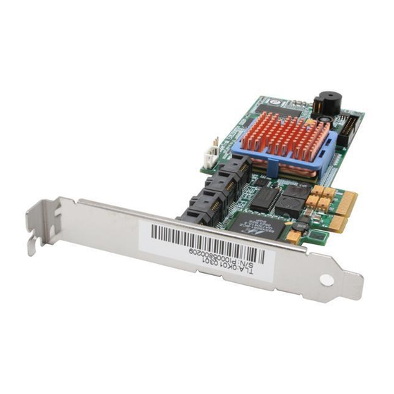
4. Names and Functions of Sections This section describes the sections on the card. (Front view) (Rear view) - Page 20 Ports 1 to 8 These channels allow the card to be connected to SATA devices. Port numbers 1 to 8 are available on this controller (depending on the server). Port 1 Port 2 Port 3 Port 4 Port 5 Port 6 Port 7 Port 8 HW label Indicates the management revision of the card.
-
Page 21: Hardware Setup
5. Hardware Setup Install the disk array controller in a server in the following procedure. Before the installation, always refer to the User’s Guide of the server. The job flow varies depending on the server type, device configuration, and existence of additional HDD cage. Check the server type and device configuration before the installation to follow the correct flow. -
Page 22: Selecting And Installing Bracket
5-2. Selecting and Installing Bracket The card is shipped with factory-installed full-height PCI bracket. To install the card on a low-profile PCI slot, the full-height PCI bracket should be replaced with the low-profile PCI bracket. Remove the screws (2) fixing the full-height PCI bracket to the card. Remove the full-height PCI bracket. - Page 23 Screw This card (disk array controller) Installation example: Rack-mount model This card (disk array controller) Screw Installation example: Tower model To connect an additional battery to the card, install the battery in the same procedure. When the card cannot be inserted into the PCI (or PCI Express) slot well, pull it out once and insert it again.
-
Page 24: Connecting Led And Sata Cables
5-4. Connecting LED and SATA Cables Connect the LED cable coming with the server to the HDD LED connector. For the connection, see the figure and the connection table below. For the connection to the motherboard, refer to the User’s Guide of the server. -
Page 25: Installing Additional Hdd Cage
5-5. Installing Additional HDD Cage To install an additional HDD cage in the server, see the procedure described in the User’s Guide coming with the additional HDD cage. 5-6. Connecting I2C Cable To use the additional HDD cage, connect the card to the cage through the I2C cable coming with the card. Connect the 3-pin connector (white) of the I2C cable to the I2C connector on the card and the 4-pin connector (black) to the backplane of the server or the additional HDD cage. -
Page 26: Forming Cables
5-7. Forming Cables To fix the SATA and I2C cables appropriately, form the cables in the following procedure. Attachment of cable clamp Attach the cable clamp coming with the card on the server. Attach the cable clamp at an arbitrary position where cables can be fixed securely. -
Page 27: Chapter 2 - Raid
Chapter 2 - RAID This chapter describes the RAID features which the disk array controller supports. 1. Overview of RAID 1-1. What is RAID (Redundant Array of Inexpensive Disks)? RAID is an abbreviation for "Redundant Array of Inexpensive Disks". The RAID technology allows more than one hard disk drive (HDD) to be handled collectively. -
Page 28: Logical Drive
1-3. Logical Drive A logical drive is configured with a group of more than one HDD. It is recognized as a physical drive by OS. Up to eight logical drives are permitted by the card when four HDDs are installed in the server. The figure below shows a sample configuration in which the disk array controller is connected with four HDDs, three of which create a logical drive and the remaining HDD is set to a single hot-spare disk. -
Page 29: Hot-Spare Disk
1-6. Hot-Spare Disk The hot-spare disk is prepared as an auxiliary HDD substituting for a defected HDD included in a logical drive which is configured at a redundant RAID level. Detecting a HDD fault, the system disconnects the HDD (or makes it offline) and starts rebuild using the hot-spare disk. The hot-spare disk can be set in two types as listed in the table below. -
Page 30: Raid Levels
2. RAID Levels This section details the RAID levels which the disk array controller can support. 2-1. Characteristics of RAID Levels The table below lists the characteristics of the RAID levels. Level Function Redundancy Characteristics RAID0 Striping Data read/write at the highest rate Largest capacity Capacity: (capacity of single HDD) ×... -
Page 31: Raid5
Disk array controller Disk 1 Disk 2 Stripe 1 Stripe 1 Stripe 2 Stripe 2 2-4. RAID5 In RAID5, data is distributed to HDDs by striping as well as in RAID0 and, at the same time, the parity (redundant data) is distributed to the HDDs. This mode is called "striping with distributed parity". Each of stripe x, stripe x+1, and parity (x, x+1) created from stripe x and stripe x+1 is recorded to a specific HDD. -
Page 32: Chapter 3 - Disk Array Controller Features
Chapter 3 - Disk Array Controller Features This chapter describes the features of the disk array controller. 1. Rebuild If a HDD is defected, the rebuild feature can recover the data in the defected HDD. The rebuild can be applied to redundant logical drives in the RAID1, RAID5, or RAID10 level. 1-1. -
Page 33: Media Patrol
2. Media Patrol The media patrol gives the read & verify test in the entire area of HDDs. It is available for all HDDs assigned to logical drives and hot-spare disks. The media patrol allows subsequent defects of HDDs to be detected and repaired. Accordingly, routine media patrol is recommended as preventive maintenance. -
Page 34: Synchronization
3. Synchronization The synchronization checks consistency among logical drives. It is available for redundant logical drives in the RAID1, RAID5, or RAID10 level. Similar to the media patrol, routine synchronization can be performed by scheduling. The synchronization checks consistency and also repairs detected error sectors in the same way as the media patrol. -
Page 35: Chapter 4 - Lamp Indications
Chapter 4 - Lamp Indications When the disk array controller is connected with an additional HDD cage or installed in the server that supports hot-swap feature, it allows you to check the access status of HDDs and other status including that under a failure or rebuild operation. -
Page 36: Indications Of Disk Lamps On Trays
2. Indications of Disk Lamps on Trays Disk lamp Indication Description Green Does not access to HDD. Rapid blink Access to HDD now. Amber ON during start Supplies power to HDD. Does not indicate that HDD is defected. ON during operation Indicates that HDD is defected or SATA cable is disconnected. -
Page 37: Chapter 5 - Creating Logical Drive
Chapter 5 - Creating Logical Drive This chapter describes the disk array controller configuration utility "SuperBuild Utility" that allows you to configure and manage the disk array. 1. Before Using SuperBuild Utility Before using the SuperBuild Utility, see the supported functions and notes described below. 1-1. -
Page 38: Notes On Creation Of Logical Drive
1-2. Notes on Creation of Logical Drive Setting hot-spare disk SuperBuild Utility cannot assign hot-spare disks. To assign hot-spare disks, use the disk array controller management utility WebPAM after OS is installed. For free HDDs unassigned to any logical drives, standby rebuild can be performed but media patrol cannot. -
Page 39: Unsupported Split Configurations
(2) Unsupported split configurations (2-1) Configuration of logical drives in different RAID levels (1) Disk array controller RAID5 LD1-1 LD1-2 LD1-3 LD size: 160GB 80GB 80GB 80GB LD2-1 LD2-2 LD2-3 RAID0 40GB 40GB 40GB LD size: 120GB HDD 1 HDD 2 HDD 3 (120GB) (120GB) - Page 40 (2-4) Configuration of logical drives created by HDDs of different capacities Disk array controller RAID5 LD1-1 LD1-2 LD1-3 LD1-4 LD size: 240GB 80GB 80GB 80GB 80GB LD1-1 LD1-2 RAID1 40GB 40GB LD size: 40GB HDD 1 HDD 2 HDD 3 HDD 4 (120GB) (120GB)
-
Page 41: Starting Superbuild Utility And Menus
2. Starting SuperBuild Utility and Menus 2-1. Starting SuperBuild Utility When the POST screen shown below appears, press the [Ctrl] + [S] keys to start SuperBuild Utility. [POST screen image (with no logical drive defined)] S u p erTrak E X 16350/16300/8350/8300(S ATAII 300) B IO S Version x.x.xxxx.xx (c) xxxx-xxxx P ro m ise Tech no lo g y, In c. -
Page 42: Main Menu
2-2. Main Menu When SuperBuild Utility starts, the Main Menu is displayed first. Then press arrow keys [↑], [↓], [←], or [→] or [Enter] key to display the screen on which you can make required settings. Controller Selection Not used in this controller. Controller Information You can view the controller information and firmware and BIOS versions. -
Page 43: Controller Selection
2-3. Controller Selection When you select [Main Menu] → [Controller Selection], a screen as shown below is displayed. This menu is used to select a target controller if one or more controller is installed. The Express5800 series server can contain only one controller, therefore, this menu is not used. -
Page 44: Controller Information
2-4. Controller Information When you select [Main Menu] → [Controller Information], a screen as shown below is displayed. You can view the firmware and BIOS versions of this controller, and assigned status on PCI bus. This menu is for information only. Tips Vendor/ Model Indicates vendor name and model name. -
Page 45: Physical Drive Management
2-5. Physical Drive Management When you select [Main Menu] → [Physical Drive Management], a screen as shown below is displayed. You can view the model name and capacity of HDDs connected on this menu. This menu is for information only. Tips Indicates the port number (Port 1 to Port 8) of connected HDD. - Page 46 Physical Drive ID Indicates the port number (Port 1 to Port 8) of the connected HDD. Model Number Indicates the vendor model name of HDD. Serial Number Indicates the vendor serial number. Firmware Version Indicates the firmware version. DMA Mode Indicates DMA mode.
-
Page 47: Logical Drive Management
2-6. Logical Drive Management When you select [Main Menu] → [Logical Drive Management], a screen as shown below is displayed. You can create or delete a logical drive on this menu. Indicates the logical drive number. Logical Drive Name Indicates the logical drive name specified in logical drive creation procedure. Capacity Indicates capacity of logical drive. - Page 48 Selecting a desired logical drive and pressing <Enter> opens the [Logical Drive Information] screen which shows the detailed information of the selected logical drive. Logical Drive ID Indicates the logical drive number. Logical Drive Name Indicates the logical drive name specified in logical drive creation procedure. Capacity Indicates capacity of logical drive.
- Page 49 (*) Cannot be identified because the HDD is in offline status or is not connected. Status Indicates the current status of logical drive. Status Description The logical drive operates normally and in online status. Critical The logical drive is in critical status. One of the HDDs configuring the logical drive is in offline status.
-
Page 50: Background Activity
2-7. Background Activity When you select [Main Menu] → [Background Activity], a screen as shown below is displayed. You can view the progress, pause, or restart the background task for logical drive (e.g., rebuild or full initialization). You can also execute some of background tasks. Device Indicates the existing logical drives. -
Page 51: Exiting Superbuild Utility
Percentage Indicates the progress of background task in percentage (%). If no background task is running, "N/A" is indicated. [Rebuild] Select this menu to execute rebuild process or restart rebuild process that has been paused. [Pause] Select this menu to pause the running background task. [Initialize] Select this menu to restart full initialization process that has been paused. -
Page 52: Creating Logical Drive
3. Creating Logical Drive This section describes the creation of a logical drive on SuperBuild Utility. 3-1. Job Flow of Creation of Logical Drives Start creation of logical drive Start SuperBuild Utility Are there existing logical drives? Are logical drives added? [Logical Drive Management] →... -
Page 53: Logical Drive Creation Procedure
3-2. Logical Drive Creation Procedure Start SuperBuild Utility. Select [Main Menu] → [Logical Drive Management]. Use an arrow key [↑] or [↓] to move cursor to [Create], and press [Enter] key. The [Create (Step 1/2)] screen is displayed. - Page 54 Check the connection status of HDDs connected to each port. [Check items] Whether all HDDs connected to the disk array controller are recognized. Whether the capacities of the HDDs are indicated correctly and whether all the HDDs have the same capacity. Whether every "Status"...
- Page 55 Provide settings required for creating logical drive. Item Default Available value RAID Level RAID0 RAID0/RAID1/RAID5/RAID10 Logical Drive Name Alphanumeric and symbol characters Physical Drive ID X X X X Do not change. Stripe Size 64 KB 32 KB/64 KB/128 KB (*1) Capacity (Free) xxxxxx MB Do not change.
- Page 56 cache memory. The access performance is improved compared with the Write Through mode. However, if an accident such as instantaneous power failure occurs, the data may be lost. Write Through This control method writes data into both cache memory and HDD simultaneously.
-
Page 57: Deleting Logical Drive
4. Deleting Logical Drive This section describes the deletion of a logical drive on SuperBuild Utility. 4-1. Logical Drive Deletion Procedure Start SuperBuild Utility. Select [Main Menu] → [Logical Drive Management]. - Page 58 Move cursor to the logical drive to be deleted, and press the <Space> key to select it. The selected logical drive is preceded by an asterisk (*) and displayed in yellow. You can select one or more logical drives. Tips Move the cursor to [Delete] and press the <Enter>...
-
Page 59: Chapter 6 - Operation And Maintenance
Chapter 6 - Operation and Maintenance 1. Maintenance Service Service representatives subordinate to or authorized by us provide services of the disk array controller with use of genuine parts and high technical capabilities. You can get the services for your own convenience. For the services, contact your sales representative. -
Page 60: Maintenance
3. Maintenance The disk array controller supports the following maintenance features: Configuration on Disk (COD) feature Rebuild feature Critical boot feature 3-1. Configuration on Disk (COD) Feature The COD feature records the configuration information in HDDs. The feature prevents the configuration information from being lost if the disk array controller is defected and replaced. -
Page 61: Replacement Of Disk Array Controller
4. Replacement of Disk Array Controller Replace the disk array controller as follows: For the handling of the server, refer to the User’s Guide of the server. Check With the power of the server being ON, shutdown OS, turn off the power of the server, and pull out the power cords from the receptacles. -
Page 62: Troubleshooting
5. Troubleshooting If the server equipped with the disk array controller does not operate normally or some utilities are disabled, check the following. Follow the action described in the relevant item if found. OS cannot be installed. Have logical drives been created? →... - Page 63 Synchronization is disabled. Is the logical drive in the critical state, isn’t it? → Replace the defected HDD and perform rebuild. Is the RAID level of the logical level RAID0, isn’t it? → Synchronization is not possible because of no redundancy in RAID0. Use media patrol for preventive maintenance of HDDs.
- Page 64 This page is deliberately left empty.