Table of Contents
Advertisement
Owner's Manual
AC/DC True RMS
Clamp Meter
Model No.
73756
CAUTION: Read, understand and
follow Safety Rules and Operating
Instructions in this manual before
using this product.
© Sears, Roebuck and Co., Hoffman Estates, IL 60179 U.S.A.
www.craftsman.com
• Safety
• Operation
• Maintenance
• Español
062006
Advertisement
Table of Contents

Related Manuals for Craftsman 73756


Summary of Contents for Craftsman 73756
- Page 1 Owner's Manual AC/DC True RMS Clamp Meter Model No. 73756 • Safety CAUTION: Read, understand and • Operation follow Safety Rules and Operating Instructions in this manual before • Maintenance using this product. • Español © Sears, Roebuck and Co., Hoffman Estates, IL 60179 U.S.A.
-
Page 2: Table Of Contents
TABLE OF CONTENTS Warranty Page 3 Safety Instructions Safety Symbols Control and Jacks Symbols and Annunciators Specifications Battery Installation Operating Instructions AC/DC Current Measurements DC Voltage Measurements AC Voltage Measurements Resistance Measurements Capacitance Measurements Frequency Measurements Temperature Measurements Continuity Check Diode Test Data Hold DC Zero... -
Page 3: Warranty
ONE YEAR FULL WARRANTY ON CRAFTSMAN PROFESSIONAL AC/DC TRUE RMS Clamp Meter If this CRAFTSMAN Professional AC/DC True RMS Clamp Meter fails to give complete satisfaction within one year from the date of purchase, RETURN IT TO THE NEAREST SEARS STORE OR OTHER CRAFTSMAN OUTLET IN THE UNITED STATES, and Sears will replace it, free of charge. -
Page 4: Safety Instructions
SAFETY INSTRUCTIONS This meter has been designed for safe use, but must be operated with caution. The rules listed below must be carefully followed for safe operation. NEVER apply voltage or current to the meter that exceeds the specified maximum: Input Limits Function Maximum Input... -
Page 5: Safety Symbols
SAFETY SYMBOLS This symbol adjacent to another symbol, terminal or operating device indicates that the operator must refer to an explanation in the Operating Instructions to avoid personal injury or damage to the meter. This WARNING symbol indicates a potentially WARNING hazardous situation, which if not avoided, could result in death or serious injury. -
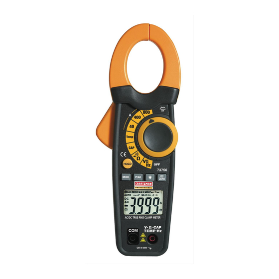
Page 6: Control And Jacks
CONTROLS AND JACKS Current clamp Clamp opening trigger Control buttons: • Data Hold • Mode • Peak • Backlight • DCA Zero Backlit LCD Display COM negative input jack for black test lead Rotary function switch V• •CAP•TEMP•HZ• positive input jack for red lead SYMBOLS AND ANNUNCIATORS HOLD Data Hold... -
Page 7: Specifications
SPECIFICATIONS Function Range Resolution Accuracy DC Current 40.00A 0.01A ± (5% + 10d) (A DC) 400.0A 0.1A ± (5% + 10d) 800A ± (2.8% + 10d) AC Current 40.00A 0.01A ± (5% + 10d) (A AC) 400.0A 0.1A ± (5% + 10d) 50/60Hz 800A ±... - Page 8 Function Range Resolution Accuracy Temperature -4 to 1ºF ± (3% reading + 9ºF) 1400ºF -20 to 1ºC ± (3% reading + 5ºC) 760ºC NOTE: Accuracy specifications consist of two elements: • (% reading) – This is the accuracy of the measurement circuit. •...
-
Page 9: Battery Installation
Operating Humidity Max 80% up to 87 F (31 decreasing linearly to 50% at 104 Storage Humidity <80% Operating Altitude 7000ft. (2000) meters maximum Weight 10.7 oz (303g) Size 9.0” x 3.1” x 2.0” (229 x 80 x 49mm) Safety For indoor use and in accordance with the requirements for double insulation to IEC1010-1 (2001):... -
Page 10: Operating Instructions
OPERATING INSTRUCTIONS WARNING: Risk of electrocution. High-voltage circuits, both AC and DC, are very dangerous and should be measured with great care. 1. ALWAYS turn the function switch to the OFF position when the meter is not in use. 2. If “OL” appears in the display during a measurement, the value exceeds the range you have selected. -
Page 11: Dc Voltage Measurements
DC VOLTAGE MEASUREMENTS CAUTION: Do not measure DC voltages if a motor on the circuit is being switched ON or OFF. Large voltage surges may occur that can damage the meter. Insert the black test lead into the negative COM terminal and the red test lead into the positive V·... -
Page 12: Ac Voltage Measurements
AC VOLTAGE MEASUREMENTS WARNING: The probe tips may not be long enough to contact the live parts inside some 240V outlets for appliances because the contacts are recessed deep in the outlets. As a result, the reading may show 0 volts when the outlet actually has voltage on it. -
Page 13: Resistance Measurements
RESISTANCE MEASUREMENTS WARNING: To avoid electric shock, disconnect power to the unit under test and discharge all capacitors before taking any resistance measurements. Remove the batteries and unplug the line cords. Insert the black test lead into the negative COM terminal and the red test lead into the V·... -
Page 14: Frequency Measurements
FREQUENCY MEASUREMENTS Insert the black test lead banana plug into the negative COM jack and the red test lead banana plug into the V· ·CAP·TEMP·Hz· positive jack. Set the function switch to the V Hz Position. Press and hold the MODE button to select the Frequency (Hz) function. -
Page 15: Temperature Measurements
TEMPERATURE MEASUREMENTS Set the function switch to the TEMP position. Insert the Temperature Probe into the negative COM and the V· ·CAP·TEMP·Hz· positive jacks, observing polarity. Touch the Temperature Probe head to the device under test. Continue to touch the part under test with the probe until the reading stabilizes. -
Page 16: Diode Test
DIODE TEST Insert the black test lead banana plug into the negative COM jack and the red test lead banana plug into the V· ·CAP·TEMP·Hz· positive jack. Turn the function switch to position. Use the MODE button to select the diode function if necessary (diode symbol will appear on the LCD when in Diode test mode). -
Page 17: Data Hold
Data Hold To freeze the LCD reading, press the HOLD button. While data hold is active, the HOLD icon appears on the LCD. Press the HOLD button again to return to normal operation. DC ZERO (Relative) The DC ZERO is a relative feature and can be used in any function. -
Page 18: Display Backlight
LCD Backlight Button The LCD is equipped with backlighting for easier viewing, especially in dimly lit areas. Press the backlight button to turn the backlight on. Press again to turn the backlight off. Note that the meter does have an auto power off feature as described below. -
Page 19: Maintenance
MAINTENANCE WARNING: To avoid electric shock, disconnect the test leads from any source of voltage before removing the back cover or the battery cover. WARNING: To avoid electric shock, do not operate your meter until the battery cover is in place and fastened securely. This multimeter is designed to provide years of dependable service, if the following care instructions are performed: 1. -
Page 20: Battery Replacement
BATTERY REPLACEMENT WARNING: To avoid electric shock, disconnect the test leads from any source of voltage before removing the battery cover. 1. When the battery becomes exhausted or drops below the operating voltage, “ ” will appear in the left-hand side of the LCD display. -
Page 21: Troubleshooting
2. Call our Customer Service Line 1-888-326-1006. SERVICE AND PARTS Item Number Description 93894 9V battery 82378 Set of black and red Test Leads 73756-D Replacement battery cover 73756-C Front Cover 73756-CS Rear cover screws 82377 Thermocouple probe For replacement parts shipped directly to your home Call 9 am –...