Table of Contents
Advertisement
Advertisement
Table of Contents

Related Manuals for IDTECK 100RV


Summary of Contents for IDTECK 100RV
- Page 1 User Manual 100RV Standalone RFID Access Controller...
-
Page 2: Table Of Contents
Table of contents ............Table of contents . - Page 3 100RV ............12...
- Page 4 100RV ............25 exceed the limit .
- Page 5 100RV ........43 8 To check the output specified for AUX 3 .
-
Page 6: Safety Information
Safety Information CAUTION: TO REDUCE THE RISK OF ELECTRIC SHOCK, DO NOT REMOVE COVER (OR BACK) NO USER SERVICEABLE PARTS INSIDE. REFER SERVICING TO QUALIFIED SERVICE PERSONNEL. This symbol indicates that dangerous voltage consisting a risk of electric shock is present within this unit. - Page 7 100RV 5. When installing the controller, fasten it securely and firmly. The fall of controller may cause personal injury. 6. Do not place conductive objects (e.g. screwdrivers, coins, metal parts, etc.) or containers filled with water on top of the controller. Doing so may cause personal injury due to fire, electric shock, or falling objects.
-
Page 8: Important Safety Instructions
100RV IMPORTANT SAFETY INSTRUCTIONS 1. Read these instructions. 2. Keep these instructions. 3. Heed all warnings. 4. Follow all instructions. 5. Do not use this apparatus near water. 6. Clean only with dry cloth. 7. Do not block any ventilation openings. Install in accordance with the manufacturer’s instructions. -
Page 9: Product Introduction
You can use the RF card to control a single door. User Registration You can register a total of 512 cards including the Master Card. Keypad Registration 100RV is equipped with the built-in keypad that you can use to register, delete cards or confi gure various settings independently. -
Page 10: Buzzer On/Off
External I/O Pins 100RV has 5 input ports and 4 output ports installed (2 relay and 2 TTL outputs). The input ports can receive signals from the Exit button and the Door Contact sensor, while the two relays can be connected to the door lock and the alarm device. -
Page 11: At A Glance
100RV At a glance Product introduction... -
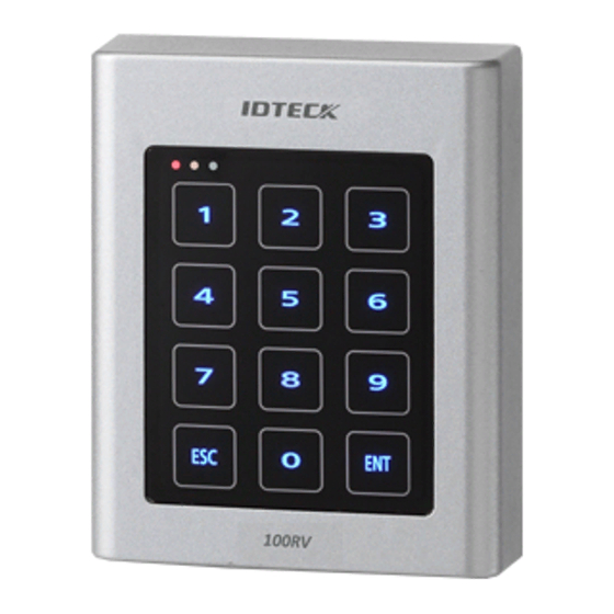
Page 12: Front / Rear
100RV Front / Rear 1. System Status LED Indicates the operation status of the system. 2. Keypad Use this to confi gure or release settings as appropriate, or enter a card number. 3. TAMPER SWITCH A tamper switch to detect falling from the wall. - Page 13 100RV Item Cable color Signal Line Description Purple NO(RL2) Alarm Relay (NO) Port Orange with white stripes TTL Output Port Brown with white stripes Chime Bell Output Input Orange EXIT Exit button connection port Yellow with red stripes CONTACT Door Contact Sensor Connection Port...
-
Page 14: Installation And External Connection
Installation and external connection Cable selection Number Item Cable type Power (DC12V) Belden #9409, 18 AWG 2 Conductor, Unshielded DC Power → This Product Reader (power and data) Belden #9512, 22 AWG 4 Conductor, Shielded External Reader → This Product Belden #9514, 22 AWG 8 Conductor, Shielded Door Contact Sensor Belden #9512, 22 AWG 4 Conductor, Shielded... -
Page 15: Bypass Diode Connection
100RV The cables should be thick enough to allow the maximum current consumed by the reader. Bypass diode connection If you connected an inductor (door locks or alarm device) to the output relay, there should occur a voltage surge while the inductor is turning on and off. If you do not connect a reverse diode to the relay, the surge voltage will cause damage to the electric circuit of the controller. -
Page 16: Exit Button Connection
100RV 1. Connect the DC 12V(+) of the power supply unit to the red line. 2. Connect the GND(-) of the power supply unit to the black line. Exit Button Connection 1. Connect one line of the Exit button to the orange line. -
Page 17: (Door Relay)
100RV Door open (POWER FAIL SAFE) when the power is disconnected from the door lock (Door Relay) 1. Connect the relay COM line (gray with red stripes for locking the door) to DC +12V. 2. Connect the relay NC line (blue with white stripes for locking the door) to the plus(+) line of the door lock. -
Page 18: External Reader Connection
100RV External reader connection Proximity Reader Connection 1. Connect the DC 12V(+) of the power supply unit to the plus (+) line of the reader. 2. Connect the GND(-) line of the power supply unit to the minus (-) line of the reader. -
Page 19: Initialization
Initialization Basic operations Initial state While the product is working normally, the orange LED indicator blinks every one second. Predefi ned Operation for a Registered Card When reading a registered card, it opens the door with the melody. Exit Button Operation If you press the Exit button, the door will be opened. -
Page 20: Duress Alarm
100RV For effective security purposes, you can set to activate the sensors (via auxiliary input ports) only in Secure mode. Duress Alarm If you are forced to open the door under a robber’s control, enter the Duress password and press with the number of your registered card (or PIN). -
Page 21: Forced Initialization With External Line
100RV Forced initialization with external line 1. Turn off the product, shortcircuit between the green line and the orange line with white stripes, and turn it back on. 2. When the initialization is completed, 3 LED indicators are blinking with a beep. -
Page 22: Reader Mode Setup
Reader mode setup You can specify the operation mode for the device. ● Once a mode is specifi ed, it will not switch until you perform the initialization. ● You must keep the Master Card in safe for later use as it is required for your change to ●... -
Page 23: Reader Mode Setup (Rf + P/W)
100RV Reader mode setup (RF + P/W) No Master Card or Master PIN is ever registered. If you remember the Master Card or the Master PIN was registered, initialize the product and try again. 1. When you turn on the product, all of the 3 LED indicators will flash with a beep. -
Page 24: Reader Mode Setup (Rf/Pin Combination Mode)
100RV Repeat the step above if you want to register PIN numbers with the device in sequence. If you don’t want to register the PIN number right now, simply jump to Step 5 above without through Step 4 above. 5. Enter the 4-6 digit Master PIN number again and press 6. - Page 25 100RV in sequence, and press You can set the device to allow you to control the door by entering the 8 digit card number using the keypad. The default is “Keypad Input Disabled”. p.20 Reader mode setup...
-
Page 26: User Management
User management To register cards in RF only mode Ensure that you must have registered the Master Card and the device is specifi ed in RF ONLY mode. 1. Present the Master Card to the device. When the mode is specified, only the green LED indicator flashes. 2. -
Page 27: To Register Cards In Pin Mode
100RV When the device enters Standby, only the red LED indicator flashes. 3. Present a card to the device, enter the 4-6 digit password and press Repeat this step if you want to register multiple cards. 4. Present the Master card to the device again, and the device will switch to normal mode. -
Page 28: To Delete A Registered Card Or Pin Number
100RV When the mode is specified, only the green LED indicator flashes. 2. Press Button and Button in sequence and press When the device enters Standby, only the red LED indicator flashes. 3. Present cards or PIN numbers (4-6 digits) to register with the device one after another, and the device will register them with a beep. -
Page 29: Basic Setup
Basic setup DURESS alarm If you are forced to open the door under the control of a criminal such as a robber, enter the predefi ned password with the number of your registered card (or PIN), which outputs the emergency TTL signal. 1. -
Page 30: To Specify The Keypad Input Suspension Time If The Retry Count With An Unregistered Id
100RV • The retry count for an unregistered ID is defaulted to “05”. To specify the keypad input suspension time if the retry count with an unregistered ID exceed the limit 1. Present the Master Card to the device. 2. Press Button... -
Page 31: To Specify The Operation Time Of The Door Contact Sensor
100RV your motion will be detected before you can get out of the secure area, which will trigger the alarm. Thus, it is recommended to set the Secure mode to get activated after a certain time. Enter the delayed start time by the minute; the sensor operation in Secure mode must have been specifi ed in advance. -
Page 32: To Specify The Alarm Output Port For The Dismantled Device
100RV 2. Press Button and Button in sequence and press 3. Enter the two-digit operation time (unit: second) and press • The default is set to “20” second. • You can specify from 10 to 99. To specify the alarm output port for the dismantled device Specify the alarm type for the dismantled device. -
Page 33: To Set Or Release The Quick Mode
100RV press To set or release the quick mode The QUICK mode is applicable to RF ONLY mode (01) and PIN ONLY mode (03) and RF/PIN combination mode (05), which enables you to open the door by simply pressing without the need of the PIN number. (This is useful for the normal business hours when the door entries and exits occur frequently.) -
Page 34: O Time Setup
I/O time setup Output Port Setting Table You must specify the port settings using whatever combination of the followings if you want the device to operate in Secure mode or normal + Secure mode. Port Setting Value Example Operation mode setting value EX 1) If only the door relay operates in normal and Operate only in Secure mode... -
Page 35: To Specify The Output Time If The Card Is Authenticated
100RV To specify the output time if the card is authenticated You can specify the output time if the card ID is authenticated. When the card ID is authenticated, the door relay and the TTL output operate for a set time. -
Page 36: To Specify The Duress Ttl Output
100RV • You can specify a two-digit time from 00 to 99 seconds. By default, only the alarm relay operates for “02” seconds in normal and Secure modes. Other output ports that are not specifi ed for the output mode will not be activated. -
Page 37: To Specify The Alarm Operation Time For Aux 1
100RV 2. Press Button and Button in sequence and press 3. Refer to the output port table on page 28 and specify a desired output mode. • If you want the alarm relay alone to operate in normal and Secure modes in case of an error from the Door contact Sensor, select the <... -
Page 38: To Specify The Alarm Operation Time For Aux 2
100RV Other output ports that are not specifi ed for the output mode will not be activated. For instance, if you set the output mode to [5][2] and assign the operation time for each output device by following the steps 4, 5, and 6 above, only the alarm relay will operate. -
Page 39: To Activate Or Deactivate The Door Relay By The Door Contact Sensor
100RV 1. Present the Master Card to the device. 2. Press Button and Button in sequence and press 3. Refer to the output port table on page 28 and specify a desired output mode. • If you want the alarm relay alone to operate in normal and Secure modes in case of an input through the auxiliary port, select the <... - Page 40 100RV The default is set to “disabled”. I/O time setup p.35...
-
Page 41: Advanced Setting
Advanced setting To specify the TTL output operation mode This is to switch the TTL output from LOW (0V) to HIGH (5V) when it is activated. 1. Present the Master Card to the device. 2. Press Button and Button in sequence and press •... -
Page 42: To Specify The Chime Bell Operation Time
100RV • To release the setting, press the < > buttons and press The default is set to “use the chime bell”. To specify the chime bell operation time You can specify the chime bell operation time. 1. Present the Master Card to the device. -
Page 43: To Specify The Input Mode For Aux 2
100RV The default is set to “switch from HIGH(5V) to LOW(0V)”. To specify the input mode for AUX 2 You can specify an operation for the auxiliary port 2 when it switches from LOW (0V) to HIGH (5V). 1. Present the Master Card to the device. -
Page 44: To Specify The Input Mode For The Exit Button
100RV To specify the input mode for the exit button You can specify an operation for the Exit button when it switches from LOW (0V) to HIGH (5V). 1. Present the Master Card to the device. 2. Press Button and Button in sequence and press •... -
Page 45: Additional Features
Additional features MUTE You can mute the keypad tone or melody in normal operation. 1. Present the Master Card to the device. 2. Press Button and Button in sequence and press • To release the setting, repeat Step 1 above, select the < >... -
Page 46: To Check The Output Specified For A Registered Card User
100RV < > buttons and press The default is set to “disabled”. You can release the alarm for the dismantled device by presenting the Master Card or a registered card. To check the output specified for a registered card user You can check the output setting that you specifi ed in “To specify the output time if the... -
Page 47: To Check The Output Specified For The Door Contact Sensor Alarm
100RV To check the output specified for the door contact sensor alarm You can check the output setting that you specifi ed in “To specify the alarm output for an input error of the Door contact Sensor”. (See page 30.) 1. -
Page 48: To Check The Output Specified For Aux 3
100RV To check the output specified for AUX 3 You can check the output setting that you specifi ed in “To specify the alarm operation time for AUX 3”. (See page 31.) 1. Present the Master Card to the device. -
Page 49: Other Information
Other information Initial values This product operates in the following initial values: For changing the settings or registering/deleting the user card, refer to the applicable section in this document. 1. Entry permitted for a registered card - The door control relay operates for 3 seconds. - The green LED indicator fl ashes for 3 seconds. -
Page 50: Function Codes
100RV 15. Control Lock by the Door Sensor : Disabled Function codes Code number Function item Additional user card registration (RF CARD ONLY MODE) Additional user card and PIN registration (RF CARD + PIN MODE) Additional PIN registration (PIN ONLY MODE) - Page 51 100RV Code number Function item Sensor Turn off the sound Turn on the sound To specify the keypad input suspension time if the retry count with an unregistered ID exceeds the limit Sense if AUX 1 switches from L to H...
-
Page 52: Troubleshooting
Set the operation mode and register the Master card and user cards as usual because the product is in the initial state. 100RV modes available : Mode Number + ENT √ RF Only : 01 + ENT √ RF + P/W : 02 + ENT √... - Page 53 Set the operation mode and register the Master card and user cards as usual because the product is in the initial state. 100RV modes available : Mode Number + ENT √ RF Only : 01 + ENT √ RF + P/W : 02 + ENT √...
- Page 54 100RV Problem Action according to the operation mode √ RF Only : 11 + ENT √ RF + P/W : 12 + ENT √ PIN Only : 13 + ENT √ RF or PIN : 15 + ENT III. Enter the user card or PIN number and provide the...
- Page 55 If the problem persists after you have followed the procedures above, contact a designated service center. 100RV can recognize a presented Check if the buzzer sounds when you press a key. RF card but can not recognize the - If you hear the buzzer sound RF card number using the keypad.
- Page 56 If the problem persists after you have followed the procedures above, contact a designated service center. The Exit button does not work at Check if the Exit button is connected to 100RV properly. all. - Ensure that the Exit button is of the NO type.
- Page 57 If the problem persists after you have followed the procedures above, contact a designated service center. The door lock does not operate at Check if the door lock is connected to 100RV properly. all. The connection method may differ depending on the type and operation mode (NO, NC) of the door lock.
- Page 58 Remove the door lock from 100RV, and check the relay output of 100RV: Replace the door lock if the relay output of 100RV shows a normal state. III. For more information, refer to the door lock connection section in the user manual.
-
Page 59: Product Specifications
Product specifications Product specifications Item 100RV User 512 Users Power / Current DC 12V / Max.180mA Reader Port External Reder Port 1ea : 26bit Wiegand for Exit Reading Time (Card) 30ms Door Open Time 00~99 Sec. (Default 3Sec.) Input Port... -
Page 60: Rma Request
(Please refer to the IDTECK webpage for more details.) 2. RMA Code will be issued after the RMA Center reviews the RMA request form. 3. Enclose the product along with the RMA Code and send it to IDTECK RMA Center. - Page 61 Tel: +82 2 2659 0055 Fax: +82 2 2659 0086 E-mail: webmaster@idteck.com Website: www.idteck.com E-Training Center: http://www.idtecktraining.com IDTECK Production Facility and RMA Center 2F, 89-4, Dodang-Dong, Weonmi-Gu, Bucheon-Si, Gyeonggi-Do 420-130, Korea Tel: +82 2 2659 0055 Fax: +82 2 2659 0086 E-mail: webmaster@idteck.com Website: www.idteck.com...
-
Page 62: Warranty Policy And Limitation Of Liability
1) to any product which has been dismantled without authorization of IDTECK or/and has a damaged or detached QC label on its back side; 2) to any losses, defects, or damages caused by improper testing, operation, installation, maintenance, modification, alteration, or adjustment;... - Page 63 100RV p.58 Warranty Policy and Limitation of Liability...
-
Page 64: Back Cover
The specifications contained in this manual are subject to change without notice at any time. 5F, Ace Techno Tower B/D, 684-1, Deungchon-Dong, Gangseo-Gu, Seoul, 157-030, Korea Tel : +82-2-2659-0055 Fax : +82-2-2659-0086 E-mail : webmaster@idteck.com FFMA0246 May. 2013 Copyright IDTECK Co., Ltd.