Table of Contents
Advertisement
Quick Links
Advertisement
Table of Contents

Related Manuals for Asus VivoMini UN66


Summary of Contents for Asus VivoMini UN66
- Page 1 VivoMini UN66 User Manual...
- Page 2 ASUS will only be responsible for or indemnify you for loss, damages or claims based in contract, tort or infringement under this Warranty Statement. This limit also applies to ASUS’ suppliers and its reseller. It is the maximum for which ASUS, its suppliers, and your reseller are collectively responsible.
-
Page 3: Table Of Contents
About this document..................5 Conventions used in this manual ............... 6 Typography ......................6 Package contents ....................7 Chapter 1: Specifications Summary ASUS VivoMini UN66 Specifications Summary ........10 Chapter 2: Product Introduction Motherboard Overview ..............14 2.1.1 Before you proceed ..............14 2.1.2... - Page 4 4.4.8 APM Configuration ..............50 4.4.9 Network Stack Configuration ...........51 Monitor menu ..................52 Boot menu ....................52 Tool menu .....................57 4.7.1 ASUS EZ Flash 3 Utility ..............57 4.7.2 ASUS SPD Information ..............57 Exit menu ....................58 Updating BIOS ..................59 4.9.1 EZ Update..................59 4.9.2 ASUS EZ Flash 3 Utility ..............60...
-
Page 5: About This Document
About this document This document provides information about the product specifications of your ASUS VivoMini UN66, organized through the following chapters: Chapter 1: Specifications Summary This chapter details the hardware and software features of your VivoMini UN Series. Chapter 2: Product Introduction This chapter describes the features of the motherboard. -
Page 6: Conventions Used In This Manual
Conventions used in this manual To highlight key information in this manual, some text are presented as follows: IMPORTANT! This message contains vital information that must be followed to complete a task. NOTE: This message contains additional information and tips that can help complete tasks. -
Page 7: Package Contents
• * *The availability and quantity of these items vary with your VivoMini package. • I f the device or any of its components fail or malfunction during normal or proper use and it is still within the warranty period, bring the device and the warranty card to you nearest ASUS Service Center. VivoMini UN Series... - Page 8 VivoMini UN Series...
-
Page 9: Chapter 1: Specifications Summary
Specifications Summary... -
Page 10: Asus Vivomini Un66 Specifications Summary
ASUS VivoMini UN66 Specifications Summary Form factor 101.6 x 101.6 x 30 mm Intel 6th generation Core™ i7-6500U Processor ® Processor Intel 6th generation Core™ i5-6200U Processor ® Intel 6th generation Core™ i3-6100U Processor ® 2 x 260 pin SO-DIMM DDR4 2133 MHz (support up to... -
Page 11: Additional Features
ASUS Business Manager ASUS Hystream ASUS Watchdog Timer Media Streamer Remote GO! eManual APRP ASUS AP ASUS Remote Management Tool ASUS EZ Installer My Logo ASUS WebStorage Additional features WinZip Adobe Reader (continued on the next page) VivoMini UN Series... - Page 12 ASUS CrashFree BIOS 3 ASUS DRAM SPD (Serial Presence Detect) memory information ASUS EZ Flash 3 Asset Tag Override DMI2.0, WfM 2.0, SM BIOS 2.7, ACPI 3.0 BIOS F12 Print Screen Last Modified Log Multi-language BIOS Quick Note UEFI AMI BIOS, PnP...
-
Page 13: Chapter 2: Product Introduction
Chapter 2: Product Introduction Product Introduction... -
Page 14: Motherboard Overview
Motherboard Overview 2.1.1 Before you proceed Take note of the following precautions before you install motherboard components or change any motherboard settings. WARNING! • U nplug the power cord from the wall socket before touching any component. • B efore handling components, use a grounded wrist strap or touch a safely grounded object or a metal object, such as the power supply case, to avoid damaging them due to static electricity. -
Page 15: Motherboard Layout
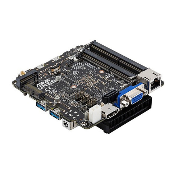
2.1.2 Motherboard layout Bottom view Connectors and slots Internal USB2.0 single port header SATA 6Gb/s connector (FFC, Flat Flexible Cable) 260 pin SO-DIMM DDR4 2133 MHz SATA 6Gb/s connector & power connector 2pin power connector(+19V, GND) Custom Solutions header (3xGPIO, 2xI C;... -
Page 16: Top View
Top view Connectors and slots CPU fan connector CEC header VivoMini UN Series... -
Page 17: Motherboard Dimensions
2.1.3 Motherboard dimensions Side view Bottom view VivoMini UN Series... -
Page 18: System Memory
2.1.4 System memory The motherboard comes with two (2) Double Data Rate 4 (DDR4) Small Outline Dual Inline Memory Modules (SODIMM) slots. VivoMini UN Series... -
Page 19: Internal Connectors
2.1.5 Internal connectors Internal USB2.0 single port header (4-pin USB2_5, USB2_6) These connectors are for USB 2.0 ports. Connect the USB module cable to any of these connectors. These USB connectors comply with USB 2.0 specification that supports up to 480 Mbps connection speed. - Page 20 2pin power connector (2-pin AUX_PWR) This power connector is used to power custom solutions. The standby power is always on, even when the board is powered off, and the presence of1.8V, 3.3V, and 5V standby power can be monitored with pins. SATA 6Gb/s connector &...
- Page 21 SATA 6Gb/s connector (FFC, Flat Flexible Cable) (10-pin SATA6G_2) This connector connects to Serial ATA 6 Gb/s hard disk drives via the Serial ATA 6 Gb/s signal FCC cable. NOTE: Ensure to use the bundled cable when connecting a hard disk drive to this connector.
- Page 22 M.2 connector (M2_TYPE_E) This M.2 slot is for the supports 2230 WiFi modules. NOTE: Ensure to use the bundled screw pack to secure the M.2 module. M.2 connector (SOCKET3) The M.2 (Socket 3) with M Key supports type 2242 (22mm x 42mm), and 2280 (22mm x 80mm) SSD modules.
- Page 23 CPU fan connector (4-pin CPU_FAN) Connect the fan cable to the fan connector on the motherboard, ensuring that the black wire of the cable matches the BLACK WIRE pin of the connector. WARNING! • D O NOT forget to connect the fan cables to the fan connector. Insufficient air flow inside the system may damage the motherboard components.
- Page 24 10. CEC header (4-pin CEC) This connector provides the standard communication signal from the HDMI connector, allowing third part solutions to monitor or control CEC activity between multiple HDMI devices. VivoMini UN Series...
-
Page 25: I/O Connectors
I/O connectors Rear panel Side panel Front panel Rear, front, and side panel connectors LAN (RJ-45) port VGA port HDMI port Power input (DC 19V) USB 3.0 ports (with BC1.2 capability) Audio jack USB 2.0 ports Consumer IR sensor VivoMini UN Series... - Page 26 VivoMini UN Series...
- Page 27 Upgrading your VivoMini...
-
Page 28: Installing Or Upgrading Memory Modules
2GB, 4GB, 8GB, or 16GB unbuffered with non-ECC 1.2 V DDR4 260-pin SO-DIMMs for a maximum of 32GB memory. IMPORTANT! Refer to http://www.asus.com for the list of compatible DIMMs. You can only install 1.2 V DDR4 SO-DIMM to the VivoMini’s DIMM slots. - Page 29 Align and insert the memory module into the slot (A) and press it down (B) until it is securely seated in place. Repeat the same steps to install the other memory module. IMPORTANT! Always install into the upper slot first. VivoMini UN Series...
-
Page 30: Installing Or Upgrading The Wireless Card
Installing or upgrading the wireless card NOTE: Your VivoMini includes a M.2 slot for 2230 wireless and Bluetooth modules. Refer to http://www.asus.com for the list of compatible wireless and Bluetooth modules. Align and insert the wireless card into the lower slot inside the VivoMini. - Page 31 (optional) Connect the antennas to your wireless card. NOTE: • C onnecting antennas to your wireless card may strengthen the wireless signal. • A soft clicking sound indicates that the antenna has been securely attached on the wireless card. • The antennas are purchased separately. VivoMini UN Series...
-
Page 32: Installing Or Upgrading The M.2 Ssd
Installing or upgrading the M.2 SSD NOTE: Your VivoMini includes a M.2 slot that supports 2280 or 2242 M.2 SSD. 3.3.1 To install or upgrade a 2242 M.2 SSD Insert the bundled hexagon screw, as illustrated. Align and insert the 2242 M.2 SSD into its slot inside the VivoMini. -
Page 33: To Install Or Upgrade A 2280 M.2 Ssd
Gently push down the 2242 M.2 SSD on top of the screw hole and fasten it using one of the bundled 3mm round screws. Refer to the illustration for the location of the screw hole. 3.3.2 To install or upgrade a 2280 M.2 SSD Align and insert the 2280 M.2 SSD into its slot inside the VivoMini. - Page 34 Gently push down the 2280 M.2 SSD on top of the screw hole and fasten it using one of the bundled 3mm round screws. Refer to the illustration for the location of the screw hole. VivoMini UN Series...
-
Page 35: Installing 2.5" Hdd Or Ssd
Installing 2.5” HDD or SSD 3.4.1 To install the HDD or SSD using the FFC SATA cable NOTE: Ensure to use the bundled Flat Flexible cable (FFC) SATA cable when installing an HDD or SSD to SATA6G_2 connector. Connect the bundled FFC SATA cable to the HDD or SSD. Connect the bundled FFC SATA cable to your VivoMini. -
Page 36: To Install The Hdd Or Ssd Using The Sata Cable
3.4.2 To install the HDD or SSD using the SATA cable NOTE: Ensure to use the bundled SATA cable when installing an HDD or SSD to SATA6G_1 connector. Connect the bundled SATA cable to the HDD or SSD. Connect the bundled SATA cable to the SATA_PWR1 and SATA6G_1 connectors on your VivoMini. -
Page 37: Chapter 4: Bios Setup
BIOS Setup... -
Page 38: Getting To Know Your Bios
Getting to know your BIOS The BIOS (Basic Input and Output System) stores system hardware settings such as Storage Device Configuration, Advanced Power Management, and Boot Device Configuration that are needed for system startup. Under normal circumstances, the default BIOS settings apply to most conditions to ensure optimal performance. -
Page 39: Bios Menu Screen
BIOS menu screen This section provides a brief introduction of the BIOS Interface of VivoMini UN Series. Quick Note (F9) Menu bar Scroll bar Language Hot Keys General help Last modified settings Submenu items Search on the FAQ Menu items Displays the CPU temperature, CPU voltage, Configuration fields... - Page 40 Move your mouse over this button to show a QR code, scan this QR code on your mobile device to connect to the BIOS FAQ web page of the ASUS support website. You can also scan the following QR code: Quick Note (F9) This button above the menu bar allows you to key in notes of the activities that you have done in BIOS.
- Page 41 Hot Keys This button above the menu bar contains the navigation keys for the BIOS setup program. Use the navigation keys to select items in the menu and change the settings. Scroll bar A scroll bar appears on the right side of a menu screen when there are items that do not fit on the screen.
-
Page 42: Main Menu
Main Menu The Main menu provides you an overview of the basic system information, and allows you to set the system date, time, language, and security settings. Security The Security menu items allow you to change the system security settings. NOTE: The Administrator or User Password items on top of the screen show the default [Not Installed]. -
Page 43: Advanced Menu
Advanced menu The Advanced menu items allow you to change the settings for the CPU and other system devices. WARNING! Be cautious when changing the settings of the Advanced menu items. Incorrect field values can cause the system to malfunction. 4.4.1 Trusted Computing NOTE: All values changed here do not take effect until computer is restarted. -
Page 44: Cpu Configuration
TPM State Allows you to enable or disable the security device. Configuration options: [Disabled] [Enabled] Pending operation Allows you to schedule an operation for the security device. Configuration options: [None] [TPM Clear] 4.4.2 CPU Configuration The items in this menu show the CPU-related information that the BIOS automatically detects. -
Page 45: Amt Configuration
4.4.3 AMT Configuration The items in this menu allow you to configure the Active Management Technology Parameters. Intel AMT Allows you to enable or disable Intel (R) Active Management Technology BIOS Extension. Configuration options: [Disabled] [Enabled] NOTE: • iAMT H/W is always enabled. • This option just controls the BIOS extension execution. -
Page 46: Pch-Fw Configuration
4.4.4 PCH-FW Configuration The items in this menu allow you to configure Management Engine Technology Parameters. TPM Device Selection Allows you to select the TPM device. Configuration options: [dTPM 1.2] [PTT] WARNING! When [dTPM 1.2] is selected, PTT/dTPM will be disabled and all data saved on it will be lost. -
Page 47: Aggressive Lpm Support
SATA Mode Selection This item allows you to set the SATA configuration. [AHCI] Set to [AHCI] when you want the SATA hard disk drives to use the AHCI (Advanced Host Controller Interface). The AHCI allows the onboard storage driver to enable advanced Serial ATA features that increases storage performance on random workloads by allowing the drive to internally optimize the order of commands. -
Page 48: Usb Configuration
4.4.6 USB Configuration The items in this menu allow you to change the USB-related features. NOTE: The USB Devices item shows the auto-detected values. If no USB device is detected, the item shows None. Legacy USB Support [Disabled] The USB devices can be used only for the BIOS setup program. It cannot be recognized in boot devices list. -
Page 49: Onboard Devices Configuration
USB Single Port Control This item allows you to enable or disable the individual USB ports. NOTE: Refer to section 2.1 Motherboard Overview for the location of the USB ports. 4.4.7 Onboard Devices Configuration HD Audio Controller [Disabled] HDA will be unconditionally disabled. [Enabled] HDA will be unconditionally enabled. -
Page 50: Apm Configuration
Change Settings Allows you to choose the setting for Super IO device. Configuration options: [IO=3F8h; IRQ=4] [IO=2F8h; IRQ=3] [IO=3E8h; IRQ=4] [IO=2E8h; IRQ=3] 4.4.8 APM Configuration ErP Ready Allows you to switch off some power at S4+S5 or S5 to get the system ready for ErP requirement. When set to [Enabled], all other PME options will be switched off. -
Page 51: Network Stack Configuration
Power On By RTC [Disabled] Disables RTC to generate a wake event. When set to [Enabled], the items RTC Alarm Date (Days) and [Enabled] Hour/Minute/Second will become user-configurable with set values. 4.4.9 Network Stack Configuration Network Stack Allows you to enable or disable UEFI Network Stack. Configuration options: [Disabled] [Enabled] NOTE: The following items appear only when you set the Network Stack to [Enabled]. -
Page 52: Monitor Menu
Monitor menu The Monitor menu displays the system temperature/power status, and allows you to change the fan settings when the items are set to [Monitor]. Selecting [Ignore] will not display any status values. CPU Q-Fan Control Allows you to enable or disable CPU Q-Fan control. Configuration options: [Disabled] [Enabled] Boot menu The Boot menu items allow you to change the system boot options. - Page 53 Next Boot after AC Power Loss [Normal Boot] Returns to normal boot on the next boot after an AC power loss. [Fast Boot] Accelerates the boot speed on the next boot after an AC power loss. Boot Logo Display [Auto] Auto adjustments for Windows requirements.
- Page 54 Launch CSM [Auto] The system automatically detects the bootable devices and the add-on devices. [Enabled] For better compatibility, enable the CSM to fully support the non-UEFI driver add-on devices or the Windows UEFI mode. ® [Disabled] Disable the CSM to fully support the non-UEFI driver add-on devices or the Windows UEFI mode.
-
Page 55: Key Management
Key Management Clear Secure Boot keys This item allows you to clear all default Secure Boot keys. Save Secure Boot Keys This item allows you to save the PK (Platform Keys) to a USB storage device. PK Management Set New Key This item allows you to load the downloaded PK from a USB storage device. -
Page 56: Boot Option Priorities
The number of device items that appears on the screen depends on the number of devices installed in the system. NOTE: • T o access Windows OS in Safe Mode, press <F8> after POST (Windows ® ® 8 not supported). • T o select the boot device during system startup, press <F8> when the ASUS Logo appears. VivoMini UN Series... -
Page 57: Tool Menu
Select an item then press <Enter> to display the submenu. 4.7.1 ASUS EZ Flash 3 Utility Allows you to run ASUS EZ Flash 3. When you press <Enter>, a confirmation message appears. Use the Left/Right arrow key to select between [via Storage Devices(s)] or [via Internet], then press <Enter>... -
Page 58: Exit Menu
Exit menu The Exit menu items allow you to load the optimal default values for the BIOS items, and save or discard your changes to the BIOS items. Load Optimized Defaults This option allows you to load the default values for each of the parameters on the Setup menus. -
Page 59: Updating Bios
BIOS setup program. EZ Update: Updates the BIOS in Windows® environment. ASUS EZ Flash 3: Updates the BIOS using a USB flash drive. ASUS CrashFree BIOS 3: Restores the BIOS using the motherboard support USB drive when the BIOS file fails or gets corrupted. -
Page 60: Asus Ez Flash 3 Utility
To update the BIOS by USB: Insert the USB flash disk that contains the latest BIOS file to the USB port. Go to the Tool menu to select ASUS EZ Flash 3 Utility and press <Enter>. Select via Storage Device(s) and press <Enter>. - Page 61 Press the Up/Down arrow keys to find the BIOS file, and then press <Enter> to perform the BIOS update process. Reboot the system when the update process is done. WARNING! • T his function can support devices such as a USB flash disk with FAT 32/16 format and single partition only. • D O NOT shut down or reset the system while updating the BIOS to prevent system boot failure! IMPORTANT! Ensure to load the BIOS default settings to ensure system...
- Page 62 To update the BIOS by Internet: Go to the Tool menu to select ASUS EZ Flash 3 Utility and press <Enter>. Select via Internet and press <Enter>. Press the Left/Right arrow keys to select an Internet connection method, and then press <Enter>...
-
Page 63: Asus Crashfree Bios 3
USB drive that contains the BIOS file. IMPORTANT! The BIOS file in the motherboard support USB drive may be older than the BIOS file published on the ASUS official website. If you want to use the newer BIOS file, download the file at https://www.asus.com/support/ and save it to a USB flash drive. - Page 64 VivoMini UN Series...
-
Page 65: Appendix
Appendix... -
Page 66: Safety Information
Safety information Your VivoMini is designed and tested to meet the latest standards of safety for information technology equipment. However, to ensure your safety, it is important that you read the following safety instructions. Setting up your system • Read and follow all instructions in the documentation before you operate your system. • Do not use this product near water or a heated source. • Set up the system on a stable surface. • Openings on the chassis are for ventilation. Do not block or cover these openings. - Page 67 • If you encounter the following technical problems with the product, unplug the power cord and contact a qualified service technician or your retailer: – The power cord or plug is damaged. – Liquid has been spilled into the system. – The system does not function properly even if you follow the operating instructions. – The system was dropped or the chassis is damaged. –...
-
Page 68: Regulatory Notices
REACH Complying with the REACH (Registration, Evaluation, Authorization, and Restriction of Chemicals) regulatory framework, we publish the chemical substances in our products at ASUS REACH website at http://csr.asus.com/english/REACH.htm ASUS Recycling/Takeback Services ASUS recycling and takeback programs come from our commitment to the highest standards for protecting our environment. - Page 69 the equipment off and on, the user is encouraged to try to correct the interference by one or more of the following measures: • Reorient or relocate the receiving antenna. • Increase the separation between the equipment and receiver. • Connect the equipment to an outlet on a circuit different from that to which the receiver is connected. • Consult the dealer or an experienced radio/TV technician for help. CAUTION! Any changes or modifications not expressly approved by the grantee of this device could void the user’s authority to operate the equipment.
- Page 70 France Restricted Wireless Frequency Bands Some areas of France have a restricted frequency band. The worst case maximum authorized power indoors are: • 10mW for the entire 2.4 GHz band (2400 MHz–2483.5 MHz) • 100mW for frequencies between 2446.5 MHz and 2483.5 MHz NOTE: Channels 10 through 13 inclusive operate in the band 2446.6 MHz to 2483.5 MHz. There are few possibilities for outdoor use: On private property or on the private property of public persons, use is subject to a preliminary authorization procedure by the Ministry of Defense, with maximum authorized power of 100mW in the 2446.5–2483.5 MHz band.
-
Page 71: Canadian Department Of Communications Statement
This requirement is likely to change over time, allowing you to use your wireless LAN card in more areas within France. Please check with ART for the latest information (www.art-telecom.fr) NOTE: Your WLAN Card transmits less than 100mW, but more than 10mW. Canadian Department of Communications Statement This digital apparatus does not exceed the Class B limits for radio noise emissions from digital apparatus set out in the Radio Interference Regulations of the Canadian Department of Communications. - Page 72 CE Mark Warning CE marking for devices without wireless LAN/Bluetooth The shipped version of this device complies with the requirements of the EMC directives 2004/108/EC (replaced in April 2016 by 2014/30/EU) “Electromagnetic compatibility” and 2006/95/EC (replaced in April 2016 by 2014/35/EU) “Low voltage directive”. CE marking for devices with wireless LAN/ Bluetooth This equipment complies with the requirements of Directive 1999/5/EC (replaced in 2017 by RED 2014/53/EU) of the European Parliament and Commission from 9 March, 1999 governing Radio...
-
Page 73: Asus Contact Information
+1-510-739-3777 +1-510-608-4555 Web site http://usa.asus.com Technical Support Support fax +1-812-284-0883 General support +1-812-282-2787 Online support http://qr.asus.com/techserv ASUS COMPUTER GmbH (Germany and Austria) Address Harkort Str. 21-23, D-40880 Ratingen, Germany +49-2102-959931 Web site http://www.asus.com/de Online contact http://eu-rma.asus.com/sales Technical Support Telephone +49-2102-5789555 Support Fax... - Page 74 VivoMini UN Series...