
Related Manuals for Fujitsu FP-1000


Summary of Contents for Fujitsu FP-1000
- Page 1 FP-1000 Thermal Printer User’s Manual Standard Model FP-1000 Built-in Power Supply Model FP-1000PW Fujitsu Isotec Limited. KA02066-Y900-04...
- Page 2 All the company names and product names mentioned in this document are the trademarks or registered trademarks of their respective companies. This document is subject to change without notice. Unauthorized reproduction or copying of this document, whether in part or in whole is prohibited.
-
Page 3: Federal Communications Commission
How to Use This Product Safely Using This Document This document contains important information for using the product safely. Carefully read and understand this manual before using the product. After reading this manual, store it with care at a place where it can be found at any time, such as near the product. - Page 4 要求以下。 ×:表示该有毒有害物质至少在该部件的某一均质材料中的含量超出SJ/T11363-2006规定的 限量要求。 Notice The contents of this manual may be revised without prior notice. No part of this manual may be reproduced in any form without permission. All Rights Reserved, Copyright 2013 Fujitsu Isotec Limited - ii -...
-
Page 5: Safety Precautions
Safety Precautions Warning Marks This document uses the following warning marks in order to ensure safe and correct use of the product and to prevent any harm or damage to you or to others. Warning Caution Used for instructions intended Used for instructions intended to to alert the user to the risk of alert the user to the risk of injury... - Page 6 Warning Only the AC adapter specified by Fujitsu Isotec may be used with this printer. Using any other AC adapter carries the risk of fire and electric shock. When connecting the drawer kick cable, do not use any method not specified in the instruction manual. This may result in fire or electric shock.
- Page 7 Do not place this product in places with high humidity, dust, smoke or bad ventilation, or in places with fire hazards. This may result in electric shock or fire. When connecting the AC adapter, do not use voltages outside the range indicated on the adapter. In addition, avoid using multiple cords connected to one outlet.
- Page 8 In case of emergency involving heat, smoke or acrid fumes occurring, immediately turn off the power switch, and remove the power plug from the outlet. Request the sales company (or maintenance service center) for repair after confirming the smoke has gone. Users must under no circumstances whatsoever try to repair the product due to the dangers involved.
- Page 9 Caution Do not place heavy objects on the product. This may destroy the balance and cause the product to fall over or down, resulting in injuries. Do not locate the product on a place with severe vibration, or on an unstable or inclined surface. The product may fall over or down, resulting in injuries.
- Page 10 When shifting the product, be sure to remove the power plug from the outlet. In addition, also remove the connection cable, etc. Pay adequate attention to your feet while performing the operation. Scratching the power cable may result in electric shock or fire, and injuries may also be caused if the product falls over or down.
-
Page 11: Table Of Contents
Table of Contents 1. Appearance and Name of Components ················································· 1 1-1. Names of Components ································································ 1 1-2. Package Contents······································································· 2 2. AC Adapter ························································································· 3 3. Paper Specifications············································································ 4 3-1. Paper Width ················································································ 4 3-2. Paper Thickness ········································································· 4 3-3. - Page 12 8-3. Printing Problems······································································ 37 9. Special Mode (Test Print, Setup Menu...) ············································ 38 9-1. Test Print ················································································· 38 9-2. Changing the Setup··································································· 40 9-3. Setup Settings ·········································································· 50 9-4. HEX Dump ················································································ 56 9-5. Command Trace········································································ 57 9-6. Sample Print ············································································· 58 10.
-
Page 13: Appearance And Name Of Components
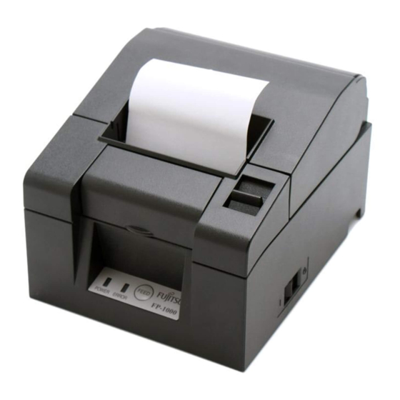
1. Appearance and Name of Components 1-1. Names of Components Standard Model Release Lever Top Cover Middle Cover Front Cover Control Panel Power Switch Built-in Power Supply Model AC Inlet Top Cover • Opens to replace paper. Release Lever • Used for opening the top cover. -
Page 14: Package Contents
1-2. Package Contents Quick Start Guide Thermal Paper Rubber Feet (For vertical installation) 58mm Width Separator Serial Interface Cable *The Serial Interface Cable is not supplied in some cases, depending on the printer model, region,etc. AC Adapter *The AC Adapter is not supplied in some cases, depending on the printer model, region,etc. -
Page 15: Ac Adapter
2. AC Adapter Only use the AC adapter specified below. Item Remarks Input : 100 to 240V, 50-60Hz, 1.1A AC Adapter KA02951-0120 Output : 24V ,1.5A Warning: Only use authorized AC adapters. Warning: Do not use any other bundled AC adapter other than designed for this printer. -
Page 16: Paper Specifications
3. Paper Specifications Only use the thermal paper roll specified below. 3-1. Paper Width • 80mm paper • 58mm paper 3-2. Paper Thickness • 65 - 85μm 3-3. Paper Roll φ83mm or less • Outside diameter: • Core diameter: φ12±0.5mm (inside) / φ18±0.5mm (outside) •... -
Page 17: Recommended Thermal Paper
3-4. Recommended Thermal Paper Manufacturer Product Quality Characteristic Paper Density Name Thickness Oji Paper Co., Monochrome thermal paper PD160R 75μm 100% Ltd. (high-grade preservation type ) Monochrome thermal paper PD190R 75μm 100% (mid-grade preservation type ) Monochrome thermal paper Nippon Paper TF60KS-E 75μm 100%... -
Page 18: Preparation
4. Preparation No printer cable is provided with the product. Obtain a printer cable suitable for the product interface. If you have any question, consult your dealer. Before connecting or disconnecting cables, make sure of the following: (1) The power to the printer and all other devices connected to the printer is turned off. -
Page 19: Connecting The Interface Cable (To The Printer)
4-1. Connecting the Interface Cable (to the printer) 4-1-1 Printers with serial and USB interfaces Standard Model USB Interface Cable Type-B * Connect the printer to a PC through this connector. Serial Interface Cable * Use the screws to secure it in place after connection. Built-in Power Supply Model USB Interface Cable Type-B * Connect the printer to a PC through this connector. - Page 20 4-1-2 Printers with LAN interfaces Standard Model LAN Interface Cable Built-in Power Supply Model LAN Interface Cable DIP Switch Power Connector LAN Interface Connector Drawer Kick Connector Caution: Do not touch the DIP switches during normal use. This may change the network settings, disabling normal printing. Caution: If the device is installed vertically, the LAN cable may be un-usable due to its shape.
-
Page 21: Connecting The Interface Cable (To The Pc)
4-2. Connecting the Interface Cable (to the PC) 4-2-1 Serial Interface (1) Connect the connector of serial interface cable to the serial port on the computer as shown in the figure. 4-2-2 USB Interface (1) Connect the connector of USB interface cable to the USB port on the computer as shown in the figure. - Page 22 4-2-3 LAN Interface (1) Connect the connector of LAN interface cable to the LAN port on the computer as shown in the figure. − 10/83 −...
-
Page 23: Connecting The Drawer Kick Cable
4-3. Connecting the Drawer Kick Cable Standard Model Drawer Kick Cable Built-in Power Supply Model Drawer Kick Cable Caution: This product uses a special-purpose modular connector for the cash drawer. Do not attempt to use other types of connectors such as public telephone connectors. −... -
Page 24: Connecting The Ac Adapter And Cable
4-4. Connecting the AC Adapter and Cable Standard Model (1) Connect the cable connector of the AC adapter to the power connector. Power Connector Flat Side Cable Connector AC Adapter Connector AC Adapter AC Inlet Power Cable Warning: Use the specified AC adapters. Warning: Use only the specified AC power cable with specifications based on national regulations. - Page 25 (2) Confirm that the cable is locked in place by gently pulling on the cable base after connection. Cable Base (3) Connect the power connector to the AC inlet of the AC adapter. The AC Inlet of the AC Adapter Power Cable (4) Insert the plug of the power cable into the outlet.
- Page 26 Built-in Power Supply Model (1) Connect the power connector to the AC inlet. Power Cable AC Inlet Warning: Use only the specified AC power cable with specifications based on national regulations. Caution: Before connecting the power cable, turn off the power switches on the printer and all the devices connected to the printer.
-
Page 27: Removing The Ac Adapter
4-5. Removing the AC Adapter To remove the cable of the AC adapter, pull it while gripping the connector section on the cable side as shown in the following figure. The lock is released, making it easy to remove. Forcibly pulling the cable will damage the connector section. -
Page 28: Installing The Printer
4-6. Installing the Printer Both horizontal installation (the paper exit is on the topside) and vertical installation (the paper exit is on the front side) orientations are available. In the case of vertical installation, attaching the optional splash-proof cover can protect the printer from water. - Page 29 Splash-proof Cover (Optional) Mount the splash-proof cover at the top when the printer is installed vertically. Splash-proof Cover Caution: The splash-proof cover is used only for vertical installation. − 17/83 −...
- Page 30 Wall Hanging Bracket (Optional) To fix the printer to a wall, follow the procedures below: (1) Mount two metal screws (thread diameter: Φ4, head diameter: Φ7) on the wall, spaced 62mm apart in a horizontal line, such that the length of each screw entering the wall is at least 10mm and the length protruding outside is 2-4mm.
- Page 31 (2) Attach the wall hanging bracket to the printer and fix it securely with the enclosed screws. Wall Hanging Bracket (3) Align the holes of the wall hanging bracket with the screws mounted to the wall and hang the printer securely. Screw Head Section −...
-
Page 32: Power On
4-7. Power On (1) Connect to the power cable according to 4-4 above. (2) Turn on the power switch at the side of the printer. After turning the power on, the POWER lamp on the control panel will light Standard Model Control Panel Power Switch Built-in Power Supply Model... -
Page 33: Installing The Printer Software
4-8. Installing the Printer Software Refer to the "Installation Guide"(*1) in the enclosed CD for instructions on installing the printer driver and utility software. *1: \Manual\Software\English\FP1000_InstallGuide1_en.pdf The "Installation Guide" can also be viewed by loading the CD in your PC's CD drive and selecting "Manuals"... -
Page 34: Inserting Paper
5. Inserting Paper 5-1. Opening the Top Cover (1) Pull the release lever in the direction of the arrow, and then open the top cover. Top Cover Release Lever Caution: Lift the cover until it is vertical so that it will stay open. Part A Part B Part C... - Page 35 Front part of Printer (Shaded part) Caution: When using printer vertically, steady the front part of the printer (shaded part in the above picture) to open the top cover. − 23/83 −...
-
Page 36: Paper Width Setting (Width: 58Mm / 80Mm)
5-2. Paper Width Setting (Width: 58mm / 80mm) As the factory setting for paper width is 80mm, follow the instructions in "5-3. Setting the Paper" to set the paper roll when using 80mm paper. When using 58mm paper, first attach the separator in accordance with the instructions in "5-2-1. - Page 37 5-2-1 Attaching the Separator (1) Align the three lugs of the supplied 58mm width separator with the corresponding holes on the printer body, then push it into place. 58mm Width Separator Setting Hole Caution: Push the plate until it locks with a clicking sound and confirm that the top side of the separator is horizontal.
-
Page 38: Setting The Paper
5-3. Setting the Paper (1) In the case of a new roll of paper, remove the glued portion and tape on the paper roll. When replacing the roll paper, first remove the old paper core. Caution: Since the glued portion of the paper should not be printed on, remove about one turn (about 30 cm) of the roll paper from the beginning so that none of the remaining paper has glue on it. - Page 39 Caution: Setting the paper as shown in the following figures may cause paper or printing jams. The paper has been set incorrectly. The paper does not pass over the top of the cover. Caution: Do not use deformed roll paper. Using rolls such as those shown below may cause trouble such as paper or printing jams.
-
Page 40: Closing The Top Cover
5-4. Closing the Top Cover Set the paper correctly and carefully close the top cover. Push Top Cover Caution: Set the paper correctly. Closing the top cover while the paper is skewed may cause a paper jam or messy printing. Caution: When closing the top cover, close it securely by pressing around the central position (shown by the arrow in the figure) until you hear a clicking sound. -
Page 41: Control Panel
6. Control Panel 6-1. Control Panel POWER lamp() If the power switch is turned on and the printer is supplied with power, this lamp will light up. ERROR lamp() This lamp lights up or blinks to indicate an error. FEED Button Pressing this button once causes the printer to feed the paper by an amount equivalent to one line. -
Page 42: Error Indications
6-2. Error Indications Recoverable errors Error State LED Lamp Blinking Pattern No paper POWER () Constantly on Paper end ERROR () Constantly on Cover open POWER () Constantly on ERROR () Constantly on Cutter jam POWER () Constantly on ERROR () Constantly on Error State LED Lamp... - Page 43 Unrecoverable errors Error State LED Lamp Blinking Pattern Internal error POWER() —— — — ERROR() ————— Repetition of two blinks of the lamp and one blink of the lamp Head not POWER() ——...
-
Page 44: Paper Jam Prevention And Removal
7. Paper Jam Prevention and Removal 7-1. Paper Jam Prevention Do not touch the paper while it is coming out or before cutting is complete. Pressing or pulling the paper with your hand while it is coming out may cause a paper jam, bad cut, or bad line feed. -
Page 45: If The Top Cover Does Not Open
7-3. If the Top Cover Does Not Open When the printer has stopped with the cutter blade exposed due to some abnormality such as a paper jam, the top cover will not open. In such a case, instead of opening it forcibly, perform the following steps: (1) Turn off the power switch to disconnect the printer from the power. - Page 46 (5) Lift the protective sheet as indicated by arrow A and rotate the cutter gear in the direction indicated by arrow B while pulling the release lever toward you. If the auto-cutter blade fails to move despite rotating the cutter gear and the top cover still will not open, pull the release lever toward you and rotate the cutter gear in the opposite direction (indicated by arrow C) until the top cover is able to open.
- Page 47 (6) Open the top cover and remove the jammed paper while holding the printer steady. Caution: When removing paper, remove the paper slowly without pulling it forcibly. Caution: As the thermal head may be damaged by static electricity, do not touch the thermal head. Also, do not touch the thermal head as it may still be hot after printing.
-
Page 48: Troubleshooting
8. Troubleshooting This section provides solutions for printer malfunctions and print quality problems. 8-1. Problems at Power-on and Other Errors Symptom Cause Solution Although the power has (1) The power cable is (1) Connect the power cable. been turned on, the disconnected. -
Page 49: Printing Problems
8-3. Printing Problems Symptom Cause Solution The printer does not (1) The interface cable is (1) Connect the interface cable print. disconnected or broken. correctly, or replace it. * Refer to 4-1. Connecting the Interface Cable (2) The printer setup is not correct. (2) Amend the setting. -
Page 50: Special Mode (Test Print, Setup Menu
9. Special Mode (Test Print, Setup Menu...) 9-1. Test Print Ensure that paper is set in the printer. Turn off the power switch on the printer, then turn it on again while pressing the FEED button on the control panel. This outputs the following printout. - Page 51 Test Print (Example) Firmware Number KA02041-Jxxx The Firmware Number and Firmware Firmware Version 01A (0xxxxx) 123456 Version vary according to the model. “123456”is an example serial number. Memory Switch 1 Power On Status Enable Receive Buffer 4KByte Busy Condition Bufferfull Receive Error ?Print Auto LF...
-
Page 52: Changing The Setup
9-2. Changing the Setup This section explains how to setup the printer without using a PC. Alternatively, when the printer is connected to a Windows PC, the settings can be changed using the utility software on the enclosed CD. For instructions on installing and using the utility software, refer to the "Installation Guide"... - Page 53 Ensure that paper is set in the printer. Turn off the power switch on the printer, then turn it on again while pressing the FEED button on the control panel. This outputs the printout shown in section 9-1. Then Press the FEED button twice (to select 2. Setup Menu) enters setup mode and prints the following menu.
- Page 54 3. Then Press the FEED button once (to select 1. Setting) enters setting mode and prints the following setting groups. Setting 1.Memory Switch 1 2.Memory Switch 2 3.Print 4.Hardware 5.Interface <Set> Press FEED button for the number of times as the same as your selecting item, and wait more than 1 second.
- Page 55 4. Then Press the FEED button three times (to select 3. Print) selects the Print group and prints the following setting options. Print 1.Paper Width 80mm/48columns 2.Max Speed 180mm/s 3.Print Density 100% <Set> Press FEED button for the number of times as the same as your selecting item, and wait more than 1 second.
- Page 56 5. Then Press the FEED button three times (select 3.Print Density) selects the Print Density setting and prints the following Print Density settings. Print Density 100% 1.70% 2.80% 3.90% 4.100% 5.110% 6.120% 7.130% <Set> Press FEED button for the number of times as the same as your selecting item, and wait more than 1 second.
- Page 57 6. Then Press the FEED button seven times (to select 7. 130%) returns to the Print settings group. Changed items are displayed in bold and underlined. Print 1.Paper Width 80mm/48columns 2.Max Speed 180mm/s 3 . P r i n t D e n s i t y 1 3 0 % <Set>...
- Page 58 7-1. Exiting to Previous Level Hold the FEED button down for 1 second or more until the buzzer sounds twice. Release the FEED button after the buzzer sounds. This returns to the previous level and prints the Setting group options. Setting 1.Memory Switch 1 2.Memory Switch 2...
- Page 59 Hold down the FEED button again for 1 second or longer until the buzzer sounds twice. Release the FEED button after the buzzer sounds. This returns to the previous level and prints the Setup Menu. Setup Menu 1.Setting 2.Setup Print 3.Save &...
- Page 60 7-2. Exiting Directly to Setup Menu Hold the FEED button down for 3 seconds or more to return to the Setup Menu. Although holding down the FEED button for a long time causes the buzzer to sound twice after 1 second, ignore this and continue to press the FEED button.
- Page 61 8. Pressing the FEED button three times (to select 3. Save & End) saves the settings, cuts the paper, and then exits setup mode. Caution: If the power switch of the printer is turned off without selecting "Save & End", any changes made will not be saved. ...
-
Page 62: Setup Settings
9-3. Setup Settings Setting Groups Settings Group Description Memory Switch 1 settings Memory Switch 1 Memory Switch 2 settings Memory Switch 2 Print settings Print Hardware settings Hardware Interface Serial and USB interface settings (This group is not displayed on printers with a LAN interface.) Setting Items and Detailed Setting Items (Note) Setup items and the default values depend on the printer model and/or area. - Page 63 (2) Memory Switch 2 Group Item Description Setting Value Recovery method for Cover Open Error Auto Recovery Cover Open Error during print Recovery by CMND What to do at power on or after recovery from error "Auto Recovery": Perform auto recovery Auto Recovery to enable data reception.
- Page 64 (3) Print Group Item Description Setting Value 80mm/48columns Paper width and number of characters 80mm/42columns Paper Width per line 58mm/35columns 58mm/32columns 100mm/s 110mm/s Maximum print speed 120mm/s 130mm/s The maximum for printing ladder Max Speed 140mm/s barcodes and two-dimensional codes 150mm/s is 120mm/s.
- Page 65 (4) Hardware Group Item Description Setting Value Whether to sound a buzzer when an error occurs None Error Alert "None": Does not beep. One Time "One Time": Beeps four times. Continuous "Continuous": Beeps continuously. The buzzer tone to use during printing Pattern 1 The buzzer beeps in the following cases Buzzer Interval...
- Page 66 *1 "Error Alert" The operation when a "continuous" buzzer tone is output is as follows: (Note) To stop the buzzer during continuous beeping, press the FEED button. Recoverable Error (Excluding Paper Near End) • Continuous beeping of 500mSecON/200mSecOFF Hardware Error •...
- Page 67 (5) Interface Group Item Description Setting Value 2400BPS 4800BPS 9600BPS 19200BPS Baud rate Baud rate for the serial interface 38400BPS 57600BPS 115200BPS 7EVEN1 7ODD1 Format Data format for the serial interface 8NONE1 8ENEN1 8ODD1 Buffer control protocol for the serial DSR/DTR Protocol interface...
-
Page 68: Hex Dump
9-4. HEX Dump Ensure that paper is set in the printer. Turn off the power switch on the printer, then turn it on again while pressing the FEED button on the control panel. This outputs the printout shown in section 9-1. Pressing the FEED button three times (select 3. -
Page 69: Command Trace
<1 B 6 1 0 2 :Set justification RIGHT (ESC a n)> <1 C 2 E :Reset kanji mode (FS .)> Fujitsu Isotec <0 A :Print and line feed (LF)> a. Undefined commands or commands with abnormal command parameters are treated as errors and printed with background and foreground reversed. -
Page 70: Sample Print
9-6. Sample Print Ensure that paper is set in the printer. Turn off the power switch on the printer, then turn it on again while pressing the FEED button on the control panel. This outputs the printout shown in section 9-1. Pressing the FEED button five times (select 5. - Page 71 To clear sample print mode, turn the power switch off and on again. Sample print mode performs a cut after each sheet is printed. Sample print mode uses the 80mm or 58mm pattern depending on the paper width setting in setup. If a recoverable error occurs, the sample print resumes after recovery.
- Page 72 <Printing Results of Sample Print, 80mm Pattern> "Receipt" Pattern "Coupon" Pattern − 60/83 −...
- Page 73 "Bar Code" Pattern − 61/83 −...
- Page 74 <Printing Results of Sample Print, 58mm Pattern> "Receipt" Pattern "Barcode" Pattern "Coupon" Pattern − 62/83 −...
-
Page 75: Regular Cleaning
10. Regular Cleaning The print quality may be impaired by paper particles, dust, or other material. To avoid this problem, remove any paper particles or dust from the paper holder, the paper transport, the platen roller, and the thermal head as described below. -
Page 76: Cleaning The Platen Roller
10-2. Cleaning the Platen Roller (1) Be sure to turn off the printer power. (2) Open the top cover. (3) Wipe off any dust, paper particles, glue, or other foreign material from the platen roller using a soft, dry cloth. Platen Roller Caution: Do not damage or dent the platen roller. -
Page 77: Cleaning The Thermal Head
10-3. Cleaning the Thermal Head (1) Be sure to turn off the printer power. (2) Open the top cover. (3) Using an alcohol solvent, remove black paper particles and other residue from the surface of the thermal head. Thermal Head Caution: The thermal head can easily be damaged. -
Page 78: Interface
11. Interface 11-1. Serial Interface (1) Transmission Interface Specifications Transmission Asynchronous Method Line Type Full duplex Input/Output Input: MAX211 Equivalent Circuit Output: MAX211 Equivalent Baud Rate 2400, 4800, 9600, 19200, 38400, 57600, 115200BPS (Setup Settings) Transmission 7 or 8 bits Code Type Transmission Start bits:... - Page 79 (2) Serial Interface Connector Pin No. Signal Name Direction Signal Line Name Signal Ground Output Transmit Data Input Receive Data Output Request to Send Input Clear to Send Input Data Set Ready Signal Ground 8~12 No Connection +24V Ground +24V Ground 15~17 No Connection +24V...
- Page 80 (3) Connection Cable The connection setup shown in the following figure is recommended. Host Printer FG < > FG DCD < > SG RXD < > TXD TXD < > RXD DTR < > RTS SG < > CT DSR < >...
-
Page 81: Usb Interface
11-2. USB Interface (1) Type-B Connector: 4 Pins Pin No. Signal Name Direction Signal Line Name VBUS Input VBUS D-inB Input/Output D+inB Input/Output Signal Ground Caution: Use a shielded USB cable. − 69/83 −... -
Page 82: Lan Interface
11-3. LAN Interface (1) LAN Interface Connector Pin No. Signal Name Direction Signal Line Name Output Output data Output Output data Input Input data Input Input data (2) LED Meaning Description Lights up when the connection is recognized as 10BASE-T Link 10BASE-T 100BASE-TX Lights up when the connection is recognized as... - Page 83 (3) DIP Switches Caution: These switches are for maintenance. During normal usage, leave them all in the OFF state. Off (Fixed) Settings Information Initialization Settings Information Self-diagnosis Print Procedures for Settings Initialization 1) Turn off the printer power. 2) Set No.2 DIP switch to ON. 3) Turn on the printer power.
-
Page 84: Drawer Kick Connector
11-4. Drawer Kick Connector Pin No. Signal Name Direction Signal Line Name Frame Ground *DRD1 Output Drawer Kick Drive Signal 1 DRSNS1 Input Drawer Sense Signal 1 +24V Drive Power *DRD2 Output Drawer Kick Drive Signal 2 Signal Ground <Connecting side> −... - Page 85 <Connection> Printer Cable Drawer 1 Drawer Open/Close Drawer Kick Solenoid (24Ω or bigger) Drawer 2 Drawer Kick Solenoid (24Ω or bigger) Caution: The drawer connection cable should be of the shielded type. Caution: Simultaneous drive from the two drives is not available. Caution: Specify the ON time and OFF time (t1 and t2) for the drawer using the pulse generation command (ESC p m t1 t2).
-
Page 86: Power Specifications
11-5. Power Specifications (1) Standard Model ±10% Operating Voltage: Current 1.5A Operating Power Consumption: During standby: 3.0W or less/0.1A (Dual Interface) 4.5W or less/0.1A (LAN Interface) During operation: 38W or less /1.5A (at 25°C, print density setting 100%, paper width 80mm, print duty 9%) (2) Built-in Power Supply Model Rated Input Voltage: 100-240V, 50-60Hz... -
Page 87: Specifications
12. Specifications 12-1. General Specifications (1) Printing Method: Direct Line Thermal Printing (2) Print Speed: Maximum 180 mm/s (Monochrome only) (3) Print Resolution: 8dot/mm (0.125mm) (4) Relationship between Number of Print Column and Character Size Body face ((Width)x(Height) dot) Paper width: 58mm 32 column printing 35 column printing ANK: Font A... - Page 88 (5) Character Sets Alphanumeric character (95) International character (16 sets : Gothic) International character (14 sets : Mincho) Enlarged graphics (128 x 20 pages : Gothic) Enlarged graphics (128 x 9 pages : Mincho (It contain a Thai page)) Down-loaded registration (96) Hangul character (2350) Big5-2003 character (13501) GB18030-2000 character (28427)
- Page 89 (7) Outline View Standard Model Built-in Power Supply Model − 77/83 −...
-
Page 90: Cutter Specifications
12-2. Cutter Specifications (1) Cutting Method: Partial cut (the paper remains connected at one point) Caution: Do not use the cutter continuously at a rate exceeding 10 cuts per minute (1 cut per 6 seconds or more). Excessive use may cause a malfunction. -
Page 91: Environment Specifications
12-5. Environment Specifications (1) Temperature Operating Operation Guaranteed at: 0°C - 40°C Print Quality Guaranteed at: 5°C - 35°C Non-operating -5°C - 60°C Transportation or storage (packaging) -20°C - 60°C (2) Humidity Operating Operation Guaranteed at: 10%-95%RH (no condensation) Print Quality Guaranteed at: 10%-85%RH (no condensation) Non-operating 8%-95%RH (no condensation) Transportation or storage (packaging) -
Page 92: Reliability Specifications
12-6. Reliability Specifications (1) Printer Life 20 million line-feed (When the recommended paper of 75μm is used) (2) Head Life Running Life: 100km (When the recommended paper of 75μm is used) Pulse Life: 100 million pulses (When the recommended paper of 75μm is used) (3) Cutter Life Paper Thickness 75μm: 1.5 million cuts (When the recommended paper of 75μm is used) -
Page 93: Usage Precautions
13. Usage Precautions 13-1. Paper Related Precautions (1) High printing rates may cause blurred printing. Choose a suitable printing rate to avoid blurring. Alternatively, set a suitable combination of print speed and print density to avoid blurring. (Refer to 9 Special Mode: 9-2. Changing the Setup.) (2) Printing characters from a non-standard character set in a thin serif or similar font will result in the characters appearing very faint. -
Page 94: Cutter Related Precautions
(8) If the paper has been left in the printer for a long time, it may deform and cause faint printing. Therefore, if the paper has been left for a long time, feed the paper forward by 20-30mm before printing. (9) If non-recommended paper is used, print quality and/or the thermal head life cannot be guaranteed. -
Page 95: Usb Interface Usage Precautions
(3) If a barcode is printed at the top of the printer paper when it is first fed, or at the bottom when paper feeding is completed, readability should be checked as accuracy in paper feeding may become unstable. 13-4. USB Interface Usage Precautions (1) Connect the printer directly to the host computer.