Table of Contents
Advertisement
MITSUBISHI Electronic Multi-Measuring Instrument
Types
ME110NSR
ME110NSR-4APH
ME110NSR-4A2P
User's Manual
Before operating the instrument, you should first read thoroughly
this operation manual for safe operation and optimized
performance of the product.
Deliver this user's manual to the end user.
ME110NSR-C
ME110NSR-MB
Three-phase 4-wire models
Advertisement
Table of Contents

Related Manuals for Mitsubishi ME110NSR


Summary of Contents for Mitsubishi ME110NSR
- Page 1 MITSUBISHI Electronic Multi-Measuring Instrument Types ME110NSR ME110NSR-C ME110NSR-4APH ME110NSR-MB ME110NSR-4A2P Three-phase 4-wire models User’s Manual Before operating the instrument, you should first read thoroughly this operation manual for safe operation and optimized performance of the product. Deliver this user’s manual to the end user.
-
Page 2: Check On Your Delivery
Check on your delivery Check the following point as soon as you receive Mitsubishi Electronic Multi-Measureing Instrument : ● The package is in good condition, ● The product has not been damaged during transit, ● The product corresponds to your order specifications, ●... -
Page 3: Table Of Contents
4.6 Menu 5 : Alarm Set-up ..........................21 4.7 Menu 6 : Analog output, Pulse output set-up ....................23 4.8 Menu 7 : Communication Set-up (ME110NSR-C) ..................26 4.9 Menu 7 : Communication Set-up (ME110NSR-MB) ................. 27 4.10 Menu 8 : Alarm output Test ........................28 5. -
Page 4: Safety Precaution
Safety precaution (Always read these instructions before using this equipment) For personnel and product safety please read the contents of these operating instructions carefully before using. Please save this manual to make it accessible when required and always forward it to the end user. Indicates that incorrect handling may cause hazardous conditions. - Page 5 ■Operation instructions CAUTION ● When the external terminals are connected to the external equipments, the instrument and the exter- nal equipments must not be powered and used until its definitive assembly on the cabinet's door. ● The rating of the terminal of the external equipment should satisfy the rating of the external terminal of this instrument.
-
Page 6: Emc Directive Instruction
EMC DIRECTIVE INSTRUCTION This section summarizes the precautions on conformance to the EMC Directive of the cabinet con- structed using this Instrument. However, the method of conformance to the EMC Directive and the judgment on whether or not the cabinet con- forms to the EMC Directive has to be determined finally by the manufacturer. -
Page 7: Features
1. Features The ME110NSR series is an instrument for measuring and metering electrical values for three-phase LV/HV electrical networks. ■Various measurement parameters Maximum Minimum Measuement parameters value value Current A1, A2, A3, AN, A Current demand DA1, DA2, DA3, DAN, DA... -
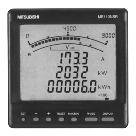
Page 8: Display And Key Functions
2. Display and Key functions ■Display HARMONICS ALARM It means that the digital displays are harmonics values. Harmonics They show direction of Power Factor or Reactive Power on bar graph. LEAD status They show the type of counting of Reactive Energy on Reactive Energy Display. LAG status They show the scales of the bar graph. - Page 9 ■Functions of operation key The operation key have various functions RESET MAX/MIN PHASE DISPLAY according to how they are pressed down. Reset key Phase change Set key Maximum/minimum +/– key Display change Meaning of code : (press), (press on over 1 second), (press on over 2 seconds), (press simultaneously) –...
-
Page 10: Function Modes
3. Function modes This meter has 3 kinds of function modes. Use it at each mode according to your requirements. ■Diagram of Each Mode Set-up mode Operation mode Set-up Menu 1 Set-up Menu 2 Set-up Menu 3 Pressing SET + RESET simultaneously Set-up Menu 4 for 2 seconds... - Page 11 ■Outline of Function Mode Operation mode Measuring and displaying in this mode. Instantaneous value display The instantaneous values of the set-up display pattern are displayed. Usually, this display is used. Maximum value and minimum value display The maximum values and minimum values are displayed. (see page 32) Cyclic display change Displays are automatically changed at every 5 seconds.
-
Page 12: Set-Up
4. Set-up 4.1 Set-up Diagram • How to access the set-up items. 1 Press the 4 After completion of set-up, select ‘End’ in the set-up menu key and the key simultaneously for RESET 2 seconds to get in the set-up mode. and press the key. - Page 13 Analog Alarm cancel ModBus Indicator module parity item 2 output 3 method reset ✽ ✽ ✽ ✽ Analog Alarm delay (ME110NSR-C) ModBus Indicator stop bit value 2 output 4 time ✽ ✽ ModBus Pulse Indicator module item 3 output reset ✽...
- Page 14 4. Set-up 4.2 Set-up Menu 1 In this set-up menu 1, set-up the basic contents as following for correct measurement . In the operation mode, after pressing the and the simultaneously for 2 seconds or more, the following RESET operation becomes available. An underline shows an initial value. Set the set-up menu number to “1”.
-
Page 15: Menu 1 : Basic Set-Up
Set-up Menu 1 (basic set-up) Sets the secondary voltage values of VT in the case of useing VT. LEAD 高 調 波 サーマル NRSTRN (phase to neutral / phase to phase) NRSTRN 最 小 大 次 テ マント 63.5V/110V NRSTRN 分... - Page 16 4. Set-up Set-up Menu 1 (basic set-up) continued From previous page !0 Set up the time constant for calculating active power demand. LEAD 高 調 波 サーマル DISPLAY 0 second 40 seconds 3 minutes 7 minutes 15 minutes NRSTRN NRSTRN 最...
-
Page 17: Menu 2 : Model Code, Lcd And Backlight Set-Up
LEAD changed.) NRSTRN NRSTRN Model type Display 最 小 大 次 テ マント – ......NRSTRN • ME110NSR 分 秒 1 Model code 最 小 大 テ マント ....varh • ME110NSR-4APH 4APH NRSTRN 最 小 大 テ マント .... -
Page 18: Menu 3 : Bar Graph, Unit, Expanded Counting, Harmonics Set-Up
4. Set-up 4.4 Bar graph, Unit, counting, harmonics set-up In this set up menu, you can do in detail set up for the bar-graph, unit, counting, harmonics. In the operation mode, press the and the simultaneously for 2 seconds or more, and the following RESET operation becomes available. - Page 19 Set-up Menu 3 5 Set the reactive power maximum scale. 5 Reactive power – maximum scale The setting method is same as that of 2 maximum scale value of active power. DISPLAY 6 Set the reactive power measure among var, kvar, and Mvar. –...
-
Page 20: Menu 4 : Index Indicator Set-Up
4. Set-up Set-up Menu 4 4.5 Index Indicator Set-up The Index indicator ( ) of bar graph is set here. Up to 4 measurement items can be set. In the operation mode, press simultaneously for 2 seconds or more, and the following operation RESET becomes available. -
Page 21: Menu 5 : Alarm Set-Up
Set-up Menu 5 4.6 Alarm Set-up This sets the upper and lower limit alarm. The upper and lower limit set value mark “ (blinking)” is displayed on the bar graph. From the display items, 4 element can be set. In the operation mode, press simultaneously for 2 seconds or more, and the following operation RESET becomes available. - Page 22 4. Set-up Set-up Menu 5 continued From the previous page 4 Set the alarm cancel method at occurrence of alarm. (screen, LEAD 高 調 波 サーマル relay) NRSTRN NRSTRN 最 小 大 次 テ マント Method Cancel method NRSTRN 分 秒 最...
-
Page 23: Menu 6 : Analog Output, Pulse Output Set-Up
Set-up Menu 6 4.7 Analog Output, Pulse Output Set-up Output item of analog output, pulse output, pulse unit and so forth are set here. In the operation mode, press the button and the button simultaneously for 2 seconds or more, and the RESET following operation becomes available. - Page 24 At initial, imported active energy is set to pulse output 1, and in NRSTRN 最 小 大 次 テ マント the case of ME110NSR-4A2P, imported reactive energy is set NRSTRN 分 秒 最 小 大 テ マント to pulse output 2, accordingly, normally press the SET...
- Page 25 !0 Set pulse output 2 item set-up (ME110NSR-4A2P) !0 Pulse output item 2 Set pulse output 2 is set as same as 8 Set pulse output item 1 set-up. DISPLAY !1 Set pulse output 2 pulse unit set-up (ME110NSR-4A2P) !1 Pulse output item 2 – pulse unit Set pulse output 2 is set as same as 9 Set pulse output 1 pulse unit.
-
Page 26: Menu 7 : Communication Set-Up (Me110Nsr-C)
4. Set-up Set-up Menu 7 4.8 Communication Set-up (ME110NSR-C) In the operation mode, press button simultaneously for 2 seconds or more, and the following RESET operation becomes available. – Set the set-up menu number to “7”. (Set as shown in the right LEAD 高... -
Page 27: Menu 7 : Communication Set-Up (Me110Nsr-Mb)
Set-up Menu 7 4.9 Communication Set-up (ME110NSR-MB) In the operation mode, press button simultaneously for 2 seconds or more, and the following RESET operation becomes available. – Set the set-up menu number to “7”. (Set as shown in the right LEAD 高... -
Page 28: Menu 8 : Alarm Output Test
4. Set-up Set-up Menu 8 4.10 Alarm output Test (only ME110NSR-4APH) Alarm circuit test is possible. (This mode is not a set-up.) In the operation mode, press the and the simultaneously for 2 seconds or more, and the following RESET operation becomes available. -
Page 30: Operation
5. Operation 5.1 Display Change By pressing DISPLAY , the measurement display will switch over. Example of display change (display pattern: P01) 高調波 サーマル 高調波 サーマル 高調波 サーマル 高調波 サーマル LEAD LEAD LEAD LEAD DISPLAY DISPLAY DISPLAY DISPLAY NRSTRN NRSTRN NRSTRN NRSTRN NRSTRN... -
Page 31: Bar Graph Display
5.3 Bar Graph Display Measurement item to be displayed on bar graph can be selected. By displaying others than the measurement items digitally displayed, 4 elements can be displayed at once. ● Explanation of bar graph (example) In the bar graph, measurement elements shown by “ ” or LEAD 高... -
Page 32: Maximum Value And Minimum Value Display
5. Operation 5.5 Maximum Value and Minimum Value Display The maximum values and the minimum values are displayed. ● Display of maximum value and minimum value When MAX/MIN is pressed, the display is changed into the maximum value and minimum value display. And when MAX/MIN is pressed, the display changes back to the present value display. -
Page 33: Cyclic Display Change
5.6 Cyclic Display Change In cyclic display, display and phases automatically change at every 5 seconds. ● Cyclic display change When DISPLAY is pressed for about 2 seconds, the cyclic display change appears. 高 調 波 サーマル LEAD NRSTRN NRSTRN 最... -
Page 34: Alarm Display And How To Cancel
5. Operation 5.7 Alarm Display and How to cancel ● Set-up Refer to 4.6 Alarm Set-up (see page 21) ● Alarm indicator If the item that had alarm set-up is displayed on the bar graph, the alarm indicator appears. By blinking of “ ”, upper or lower limit is shown. -
Page 35: Harmonics Display
5.8 Harmonics Display Harmonic RMS value and distortion ratio ratio can be displayed. ● Measurement items Current Voltage Degree Distortion Distortion value ratio value ratio Harmonic total 11th 13th ✽ Even when the RMS value of voltage harmonics is set to phase to phase voltage display, it is displayed in phase to neutral voltage. ●... -
Page 36: Expanded Counting Display
5. Operation 5.9 Expanded Counting Display Measured value display and enlarged 3 digital figures display of active energy and reactive energy can be displayed. ● Active energy and reactive energy display Active energy and reactive energy are displayed on the lower stage. Display type is as shown in the right table according to total Total load Display type... -
Page 37: Set Value Confirmation Mode
5.10 Set Value Confirmation mode In the set value confirmation mode, set value confirmation, indicator and alarm setting change, and back light auto off can be made. In this set value confirmation mode, other set-up than the following set-up menus cannot be set (or changed), which prevents changing other set values by mistake in operation. -
Page 38: Others
6. Others 6.1 How to rearrange the Display Pattern (P00) Even if there is no display pattern that you like in the display patterns P01 to P13, individual set-up is available by the display pattern P00. This set-up is made in the set-up menu 1. Explanation begins with the set “P00” in 2 display pattern of the setting menu 1 (page 14). - Page 39 5) Set the display of the display 4-2. 高 調 波 サーマル LEAD – select “YES” NRSTRN NRSTRN and press 最 小 大 次 テ マント NRSTRN 分 秒 最 小 大 テ マント varh When not to display the display 2, select “no” NRSTRN 最...
-
Page 40: Display Pattern Contents
6. Others 6.2 Display Pattern Contents When the display elements are set in the set-up menu 1 and the set-up menu 3, by pressing DISPLAY , display transit from No.1 in the order shown in the table below. Additional display varh varh varh... -
Page 41: Maximum Scale Value
6.3 Maximum Scale value Settable primary voltage, primary current, and standard maximum scale value are shown in the tables below. ● Specific power value for scale calculation (table 1) ● Maximum scale value of each item Measurement element Maximum scale value Rated voltage Specific power Specific power... -
Page 42: Maximum Scale Table
6. Others 6.4 Maximum Scale Table The maximum scale of A, W, and var can be selected in the range from about 40% to about 120% of ratings, from scale conditions, the values of the table below are applied. This is same to measured values to correspond to the maximum output of analog output. - Page 43 Power maximum scale value (2/2) Reactive power maximum scale value (1/2) Reactive power maximum scale value (2/2) STEP W unit kW unit MW unit STEP var unit kvar unit Mvar unit STEP var unit kvar unit Mvar unit 220kW 90var 96kvar 240kW 100kvar...
-
Page 44: Measurement Characteristic
6. Others 6.5 Measurement Characteristic ■ Metering actions in other than operation mode Status Measurement Display Analog output Alarm contact point Pulse output Several seconds just No measurement No display Output over Opened No output after turning on the about 100% may auxiliary power supply be made until (Backlight is lit, and... -
Page 45: Troubleshooting
6.6 Troubleshooting In the case of abnormal noise, odor, smoke, heat generation from this instrument, turn it off at once. And if you think the instrument is erroneous, check the followings before you ask for repair. Condition expected cause Solution The display is not lit. -
Page 46: Installation 1. Dimensions
Installation 1. Dimensions... -
Page 48: Mounting
Installation 2. Mounting ±1 1 Dimensions of the panel The panel hole dimensions are as shown below. And it can be attached to a panel of thickness 1.6 - 4.5mm. 2-f6 Panel hole dimensions (Viewed from the front of panel) 2 View angle The contrast of the display changes at view angles. -
Page 49: Wiring
Installation 3. Wiring 1 Open the one side of the terminal cover. Input terminal cover Output terminal cover (Not included in ME110NSR) (Viewed from the top) 2 Wiring CAUTION Wirings of the terminals have to be fastened according to the following table. -
Page 50: Wiring Diagram
0.5 and 5A. Note ) In the case of low voltage, there is no need for grounding of the secondary sides of VT and CT. Three-phase 4-wire type : example of ME110NSR-4A2P (on condition for direct input) Analog output CH1 –... - Page 51 ■ Output Wiring Diagrams ME110NSR-C CC-Link Communication Protective earthing Auxiliary power supply 100-240V AC 100V DC Fuses gG type (IEC269) or M type rated between (–) 0.5 and 5A. 1. As for CC-link cable, use the designated cable. 2. CC-Link exclusive cable and CC-Link exclusive high performance cable cannot be used in mixed.
-
Page 52: Specification
Specifications Specifications Item Specification Type ME110NSR, ME110NSR-4APH, ME110NSR-4A2P ME110NSR-C, ME110NSR-MB Phase wire system Three phase 4-wire Measuring input rated 5A, max 254V/440V 50-60Hz Items Display Output Measuring Current A1, A2, A3, AN, Aavg Accuracy Current Demand DA1, DA2, DA3, DAN, DAavg... -
Page 53: Communication Specifications
Part of recommended cables of twist pair cables to be used in CC-Link are introduced below. As for details, refer to “Mitsubishi Electric Open Field Network CC-Link”. By the way, CC-Link performance is not guaranteed with other than the recommended cables. -
Page 54: Set-Up Table
Specifications Set-up Table Set-up menu No. Set-up item Initial content ME110NSR ME110NSR-4APH ME110NSR-4A2P ME110NSR-C ME110NSR-MB Phase display Phase to neutral Display pattern 1.2.1 Pattern 00 – Using VT or direct input no (direct input) 1.3.1 Direct voltage 254V/440V 1.3.2 VT secondary voltage 63.5V/110V... -
Page 56: Example Of Simple Set-Up
Example of Simple Set-up A simple set-up example is shown below. ■Set-up example Model type: ME110NSR-4APH Phase line system: Three-phase 4-wire Measurement items: A, V, W, cosf Input voltage: 254V direct Primary current: 200A Active power maximum scale: 160kW (standard : rating 100%) - Page 57 It is set to “V ” at initial, so press SET as it is. Analog output 2 (L-N) It is set to “W∑” at initial, so press SET as it is. Analog output 3 Analog output 3 It is set to “160kW (100%)” at initial, so press SET as it is. power span Analog output 3 It is set to “one side fluctuation input”...
- Page 60 Taipei Hsien Taiwan 77/12 Bumrungmuang Road, Klong Mahanak, 223-4220-3 UNITED TRADING & IMPORT CO. LTD. Thailand Pomprab Bangkok 10100. HEAD OFFICE: MITSUBISHI DENKI BLDG., MARUNOUCHI, 2-2-3, CHIYODAKU, TOKYO 100-8310. TELEX: J24532 CABLE: MELCO TOKYO LM305Z196H01 Recycled paper used IB63370. 0602(MDOC)