Panasonic BB-HCM511A Service Manual
Hide thumbs
Also See for BB-HCM511A:
- Installation manual (4 pages) ,
- Product catalog (125 pages) ,
- Operating instructions (1 page)

Related Manuals for Panasonic BB-HCM511A


Summary of Contents for Panasonic BB-HCM511A
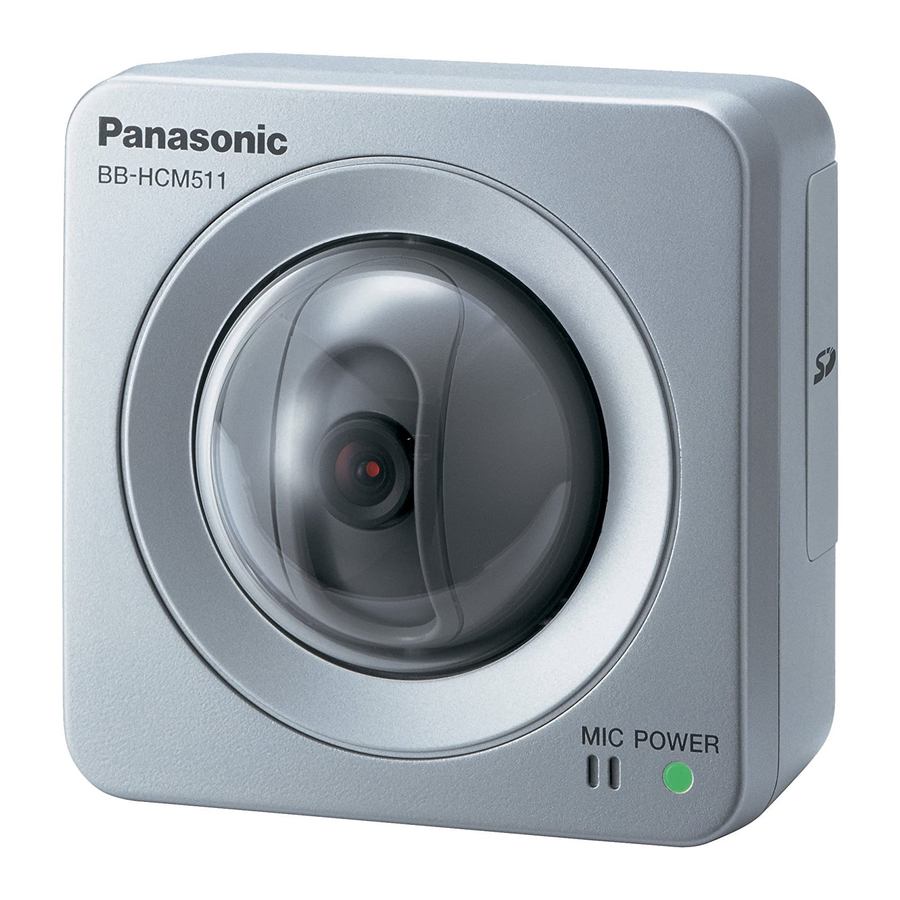
- Page 1 ORDER NO. KMS0703309CE Network Camera BB-HCM511A BB-HCM531A (for U.S.A.) © 2007 Panasonic Communications Co., Ltd. All rights reserved. Unauthorized copying and distribu- tion is a violation of law.
-
Page 2: Table Of Contents
9 Maintenance ------------------------------------------------------ 49 9.1. Cleaning the Camera------------------------------------ 49 10 Block Diagram --------------------------------------------------- 50 11 Schematic Diagram--------------------------------------------- 51 11.1. CPU BOARD (PCB1) [BB-HCM511A] -------------- 51 11.2. CPU BOARD (PCB1) [BB-HCM531A] -------------- 59 11.3. I/O Board (PCB2) ---------------------------------------- 67 11.4. PoE Board (PCB3)--------------------------------------- 69 11.5. -
Page 3: Warning
When the lithium battery is exchanged, the clock settings are cleared. In this case, make clock settings again. Recommend Type Number: CR2032/1VC1 (BAT501) Manufactured by MATSUSHITA [for BB-HCM511A] BR-2032-1VC (BAT501) Manufactured by MATSUSHITA [for BB-HCM531A] CR Coin Cell Lithium Battery Information: This product contains a CR Coin Cell Lithium Battery which contains Perchlorate Material - special handling may apply. - Page 4 BB-HCM511A/BB-HCM531A 1.2.1. Suggested PbF Solder There are several types of PbF solder available commercially. While this product is manufactured using Tin, Silver, and Copper, (Sn+Ag+Cu), you can also use Tin and Copper, (Sn+Cu), or Tin, Zinc, and Bismuth, (Sn+Zn+Bi). Please check the manufacturer’s specific instructions for the melting points of their products and any precautions for using their product with other materials.
- Page 5 BB-HCM511A/BB-HCM531A I/O BOARD PoE BOARD...
-
Page 6: For Service Technicians
BB-HCM511A/BB-HCM531A CAMERA BOARD 1.3. For Service Technicians ICs and LSIs are vulnerable to static electricity. When replacing, the following precautions will help to prevent recurring malfunctions. 1. Cover the plastic parts with aluminum foil. 2. Ground the soldering irons. 3. Use a conductive mat on the work-table. -
Page 7: Specifications
BB-HCM511A/BB-HCM531A 2 Specifications 2.1. Network Camera Items Specifications 10x (by area) digital zoom Zoom Pan/Tilt Angle Pan: -60 ° to +60 ° , Tilt: -45 ° to +20 ° Number of Pixels 1/4 inch CCD sensor, 320,00 pixels Illuminance 2-100,000 lx (0.2-100,000 lx when in Color Night View mode) - Page 8 Dimensions (W x H x D) 100 mm x 100 mm x 74 mm (3 15/16 inches x 3 15/16 inches x 2 15/16 inches) BB-HCM511A : 330g (0.73 lb.) Weight (Main Unit Only) BB-HCM531A : 335g (0.74 lb.) Power Supply AC adaptor : Input 100—120 V AC, 50/60 Hz...
-
Page 9: Features
Camera images can be recorded to an optional SD memory card in addition to the camera’s internal memory. The camera sup- ports Panasonic SD memory cards from 64 MB to 2 GB in capacity, allowing you to store thousands of camera images on a sin- gle card. -
Page 10: Technical Descriptions
BB-HCM511A/BB-HCM531A 4 Technical Descriptions 4.1. CPU Peripheral Block • The IC102 is a system LSI for a network camera containing the CPU • The power supply voltages are +3.3V (I/O) and +1.2V(inside). • The CPU is performs mainly hardware control, TCP/IP protocol processing and applications such as http and FTP. -
Page 11: Camera Block
BB-HCM511A/BB-HCM531A 4.2. Camera Block [Camera (CCD) Board] • C701 is a CCD image sensor module with approx. 320 thousand pixels, and outputs the image signal (CCD_OUT) in VGA size (640×480). IC704 outputs Pixel clock (CAMCLK) and CCD_H drive signal based on the timing of synchronized signal (CAM_HD, CAM_VD) from CPU Board after receiving CLOCK signal from IC715. -
Page 12: Image Compression Block
BB-HCM511A/BB-HCM531A 4.3. Image Compression Block • Image compression (JPEG/MPEG-4 encode) function, memory control unit (MCU), ETHERNET MAC, and SD card controller are built into IC102. • Picture data input from the camera block is captured in SDRAM (1). • Captured image data is input to the ZOM block, where the scaling of the image size is done, (an image size of 640 x 480, 320 x 240, or 192 x 177 is generated from the one with the size of 1280 x 1024, or an image size of 320 x 240 or 192 x 177 from the one with the size of 640 x 480), and is stored in SDRAM again (2). -
Page 13: Audio Block
BB-HCM511A/BB-HCM531A 4.4. Audio Block External Microphone Jack (CN505) Used with the external microphone. Audio Output (CN504) Used when connecting a speaker with a built-in amplifier, when the audio is output from a camera. Microphone Detection (Q501) When the external microphone plug is not inserted, pins 3 and 2 of the Microphone Jack (CN505) are short-circuited and a base current is supplied to Q501 through R501, R506 and R505 so that the Q501 goes ON and a collector (MIC_S signal) goes LOW. -
Page 14: Lan Block
BB-HCM511A/BB-HCM531A a register setting from the host, amplification, AD conversion and gain adjustment are performed. The sampling frequency of the A/D conversion is 8kHz and it is converted to the PCM in the format of 8bit and µ law. Then, 64kbps data are output to the IC102 on the CPU board through the Serial I/F. -
Page 15: Pan And Tilt Motor Control Circuit
BB-HCM511A/BB-HCM531A 4.6. Pan and Tilt Motor Control Circuit Pan and tilt are conducted by controlling the motor driver (IC108) using the signal from GPIO inside of IC102, which is mounted on the CPU board. Also, detection of a home position for operating the pan and tilt are done with the pan photo sensor (IC116 on the CPU board) and the tilt photo sensor (IC2 on the FPC board). -
Page 16: Poe Block
BB-HCM511A/BB-HCM531A 4.8. PoE Block [Power receive] The power supplied from a LAN cable receives voltage (48 V) via a diode bridge from a RJ-45 connector (CN601) on the PoE Board. There are 2 types of PoE receiving methods; a type using unused pins (4, 5, 7 and 8 pin) for LAN data transmission and a type using the mid point of data lines (1, 2, 3 and 6 pin). -
Page 17: Others
BB-HCM511A/BB-HCM531A 4.9. Others [I/O Terminal] • The Input terminal has two systems; both of them are connected to the Input Port of the IC102 GPIO. • Due to Internal Pull-up Resistance, the PNP Transistor (Q502, Q503) on the following level is usually in the OFF state and the Input Port connected to the collector is at L level. -
Page 18: Location Of Controls And Components
BB-HCM511A/BB-HCM531A 5 Location of Controls and Components Understanding the Camera Indicator The camera’s indicator lights as follows according to the status of the camera. Understanding how and when the indicator lights can help you troubleshoot problems with the camera. Camera Status or Operation... -
Page 19: Installation Instructions
Before proceeding, confirm that your PC is connected to your router and can access the Internet. Also confirm that your router’s UPnP™ feature is enabled. (Most routers have UPnP™ turned off by default.) Refer to the operating instructions included with your router or to the Panasonic Network Camera website (http://panasonic.co.jp/pcc/products/en/netwkcam/) for more information. 6.1.1. - Page 20 BB-HCM511A/BB-HCM531A 6.1.3. Connecting External Audio Devices 6.1.4. Connecting a Video Device...
- Page 21 BB-HCM511A/BB-HCM531A 6.1.5. Connecting External Sensors...
-
Page 22: Setup
BB-HCM511A/BB-HCM531A 6.2. Setup Abbreviations • UPnP is the abbreviation for “Universal Plug and Play”. • The Network Camera is referred to as “the camera” in this section. • The Setup CD-ROM is referred to as “the CD-ROM” in this section. - Page 23 Note: The CD-ROM includes a single camera version of the Panasonic Network • In order to configure the camera for access over the Internet using these instructions, your Camera Recorder software. Click [Manual] on the Network Camera Setup ™...
-
Page 24: Mounting The Camera
• Make sure you attach the safety wire when mounting the camera, to prevent the camera from falling. Note: • For BB-HCM511A: The camera is intended for indoor use only and should not be mounted outdoors. • For BB-HCM531A: If you install the camera outdoors, the external microphone or speaker must be outdoor compatible. - Page 25 BB-HCM511A/BB-HCM531A 6.3.1. Flexible Stand Mount 3. For BB-HCM511A: Connect all necessary cables (AC adaptor, LAN, audio/ video, etc.). Then skip to step 7. 1. Screw the threaded mount into the stand/tripod mounting For BB-HCM531A: hole. Pass the cables through the connector cover, and then 2.
- Page 26 Wiring through a hole made in the ceiling or wall • Be careful not to nip the cables. For BB-HCM511A: (INDOOR USE ONLY) • Make sure the flexible stand is firmly mounted on a beam Make a hole for cables in the ceiling or wall. Secure the safety of wood (25 mm [1 inch] and greater) etc.
-
Page 27: Troubleshooting Guide
BB-HCM511A/BB-HCM531A 7 Troubleshooting Guide 7.1. Basic Operation Reference A : Other Function Check (P.28) K : LED Circuit Check (P.39) B : Power Supply Block Check (P.29) L : Diagnosis NG Check (P.40) C : CPU Peripheral Block Check (P.30) M : Version Upgrade Check (P.41) -
Page 28: Other Function Check
BB-HCM511A/BB-HCM531A 7.2. Other Function Check Reference D : Image Block Check (P.31) J : RTC Circuit Check (P.38) G : Motor Block Check (P.35) H : I/O Terminal Check (P.36) I : SD Card Block Check (P.37) -
Page 29: Power Supply Block Check
BB-HCM511A/BB-HCM531A 7.3. Power Supply Block Check... -
Page 30: Cpu Peripheral Block Check
BB-HCM511A/BB-HCM531A 7.4. CPU Peripheral Block Check Note: Refer to Waveform (P.78) for Waveform A1-A5. -
Page 31: Image Block Check
BB-HCM511A/BB-HCM531A 7.5. Image Block Check Note: Refer to Waveform (P.78) for Waveform. -
Page 32: Audio Block Check
BB-HCM511A/BB-HCM531A 7.6. Audio Block Check Note: Refer to Waveform (P.78) for Waveform. - Page 33 BB-HCM511A/BB-HCM531A Note: Refer to Waveform (P.78) for Waveform.
-
Page 34: Lan Block Check
BB-HCM511A/BB-HCM531A 7.7. LAN Block Check Note: Refer to Waveform (P.78) for Waveform. -
Page 35: Motor Block Check
BB-HCM511A/BB-HCM531A 7.8. Motor Block Check Note: Refer to Waveform (P.78) for Waveform. -
Page 36: I/O Terminal Check
BB-HCM511A/BB-HCM531A 7.9. I/O Terminal Check... -
Page 37: Sd Card Block Check
BB-HCM511A/BB-HCM531A 7.10. SD Card Block Check... -
Page 38: Rtc Circuit Check
BB-HCM511A/BB-HCM531A 7.11. RTC Circuit Check Note: Refer to Waveform (P.78) for Waveform. -
Page 39: Led Circuit Check
BB-HCM511A/BB-HCM531A 7.12. LED Circuit Check... -
Page 40: Diagnosis Ng Check
BB-HCM511A/BB-HCM531A 7.13. Diagnosis NG Check... -
Page 41: Version Upgrade Check
BB-HCM511A/BB-HCM531A 7.14. Version Upgrade Check... -
Page 42: Resetting The Camera
BB-HCM511A/BB-HCM531A 7.15. Resetting the Camera You can reset all of the camera’s settings to their factory default settings. 1. Click the [Maintenance] tab. 2. On the left side of the screen under [Maintenance], click [Reset to Factory Default]. 3. Click [Execute]. -
Page 43: How To Change Mac Address Label
BB-HCM511A/BB-HCM531A 7.16. How to Change MAC Address Label MAC address label caution When you replace the CPU board, you must also attach the new MAC address label (included with the replacement CPU board). Attach the new MAC address label to the unit by placing over the old MAC address label. Make sure the old address cannot be seen. -
Page 44: How To Replace The Flat Package Ic
BB-HCM511A/BB-HCM531A 7.17. How to Replace the Flat Package IC Even if you do not have the special tools (for example, a spot heater) to remove the Flat IC, with some solder (large amount), a soldering iron and a cutter knife, you can easily remove the ICs that have more than 100 pins. - Page 45 BB-HCM511A/BB-HCM531A 7.17.3. Flat Package IC Installation Procedure 1. Temporarily fix the FLAT PACKAGE IC, soldering the two marked pins. *Check the accuracy of the IC setting with the corresponding soldering foil. 2. Apply flux to all pins of the FLAT PACKAGE IC.
-
Page 46: Disassembly And Assembly Instructions
BB-HCM511A/BB-HCM531A 8 Disassembly and Assembly Instructions 8.1. Disassembly Instructions MAC address label caution When you replace the CPU board, you must also attach the new MAC address label (included with the replacement CPU board). Attach the new MAC address label to the unit by placing over the old MAC address label. Make sure the old address cannot be seen. - Page 47 BB-HCM511A/BB-HCM531A 8.1.2. How To Remove I/O Board and PoE Board • 1, 2 are the same as 8.1.1. How To Remove CPU Board (P.46). 3. Remove four Screws (B). 4. Remove MIC read. 5. Remove CPU Board, I/O Board and PoE Board.
- Page 48 BB-HCM511A/BB-HCM531A 8.1.3. How To Remove FPC Board and Camera Board • 1, 2 are the same as 8.1.1. How To Remove CPU Board (P.46). • 3, 4, 5 are the same as 8.1.2. How To Remove I/O Board and PoE Board (P.47).
-
Page 49: Maintenance
BB-HCM511A/BB-HCM531A 10. Remove Eye left Cover, Eye center Cover and Eye right Cover from Camera Board. 11. Remove two Screws (B) from Eye right Cover, and remove FPC Board. 9 Maintenance 9.1. Cleaning the Camera For best performance, we recommend cleaning the camera periodically. Turn the camera off before cleaning it. -
Page 50: Block Diagram
BB-HCM511A/BB-HCM531A 10 Block Diagram... -
Page 51: Schematic Diagram
BB-HCM511A/BB-HCM531A 11 Schematic Diagram Note: Refer to Waveform (P.78) for waveform. 11.1. CPU BOARD (PCB1) [BB-HCM511A] CAM_MCLK +3.3V +3.3V CCD[11-0] TP_EX_BUSY C112 C118 (Power Reset) C120 +3.3V +3.3V C102 X101 100p L102 0.1u 48MHz TP_NRESET DGND DGND R108 C113 2 VDD... - Page 52 VSS28 VDD17 VDD18 VDD19 DGND SDA[11-0] VDD20 +3.3V VDD21 SDD[31-0] VDD22 VDD23 TP_VDDQ VDDQ VSSV17 IC115 VSSV7 VSSV6 VDDI VDDQ VSSV5 VOUT DGND VDDQ DGND L103 DGND +1.2V_VDDI DGND DGND DGND AVDD DGND VIDEOOUT Q101 AGND BB-HCM511A: CPU BOARD_No.1 (2/2)
- Page 53 LED3/NWAYEN 49.9/1% MII_RXDV LED2/DUPLEX RXDV/PCS_LPBK 10 RXC LED1/SPD100 MII_RXCLK L112 241 11 RXER/ISO LED0/TEST 12 GND12 INT#/PHYAD0 RA101 4.7k DGND MII_RXER C178 0.1u DGND L114 MII_TXCLK DGND DGND DGND MII_TXEN MII_TXD0 MII_TXD1 MII_TXD2 MII_TXD3 MII_COL MII_CRS N_P_DOWN BB-HCM511A: CPU BOARD_No.2...
- Page 54 MIC_S R158 A_FCK A_FCK R159 A_DTI A_DTI R160 A_BCK A_BCK R161 A_DTO A_DTO R162 PCM_D PCM_O R163 PCM_CLK PCM_CLK R164 PCM_NCS PCM_NCS GND23 R153 LED_R LED_R R152 LED_G LED_G +3.3V +3.3V26 L119 +3.3V27 CN102 BB-HCM511A : CPU BOARD_No.3 (1/2) DGND...
- Page 55 2 SDCMD 3 GND1 4 VSD L128 SDIOCLK 5 SDCLK 6 GND2 R190 SDIOD0 7 SDDAT0 R191 SDIOD1 8 SDDAT1 R192 SDIOD2 9 SDDAT2 R193 SDIOCD 10 CARDDET 11 VDD33 R194 SDIOWP 12 SDWP DGND DGND BB-HCM511A : CPU BOARD_No.3 (2/2)
- Page 56 BB-HCM511A/BB-HCM531A +3.3V R117 AC_STOP +3.3VMOT +3.3VMOT Q102 D103 DGND DGND DGND DGND +3.3V +12V +3.3V IC111 L121 L124 +1.2V_VDDI +1.2V IC117 IC114 Vout R208 Vout GND2 GND3 GND4 DGND BB-HCM511A : CPU BOARD_No.4...
- Page 57 MEGA_RST +3.3V +3.3VMOT +3.3V22 L108 +3.3V23 4.7u GND24 GND25 +3.3V26 DGND R233 PHO_STOP R234 TILT_SENS TILT_SENSE R235 TILT_4 TILT4 R236 TILT_3 TILT3 R237 TILT_1 TILT2 31 R238 TILT1 32 TILT_2 R242 Q103 PHO_STOP (23) DGND BB-HCM511A : CPU BOARD_No.5 (1/2)
- Page 58 CCD[3] Cr_in[9] Cr_OUT[9] CAMD[4] CCD[4] CAMD[5] CCD[5] Cb_in[0] Cb_OUT[0] CAMD[6] CCD[6] Cb_in[1] Cb_OUT[1] CAMD[7] CCD[7] Cb_in[2] Cb_OUT[2] Cb_in[3] Cb_OUT[3] RA105 47 Cb_in[4] Cb_OUT[4] Cb_in[5] Cb_OUT[5] Cb_in[6] Cb_OUT[6] Cb_in[7] Cb_OUT[7] Cb_in[8] Cb_OUT[8] Cb_in[9] Cb_OUT[9] DGND (23) BB-HCM511A : CPU BOARD_No.5 (2/2)
-
Page 59: Cpu Board (Pcb1) [Bb-Hcm531A]
BB-HCM511A/BB-HCM531A 11.2. CPU BOARD (PCB1) [BB-HCM531A] C112 CAM_MCLK +3.3V +3.3V TP_EX_BUSY CCD[11-0] C118 (Power Reset) C120 +3.3V +3.3V C102 X101 100p L102 0.1u 48MHz TP_NRESET DGND DGND DGND R108 C113 R105 C111 DGND IC101 0.1u DGND DGND DGND NRST_SW DGND +3.3V... - Page 60 BB-HCM511A/BB-HCM531A SDBA0 SDBA1 SDDQM3 SDDQM2 SDDQM1 SDDQM0 SDWEB SDCASB SDRASB SDCS SDCKE R123 DRAMFCK C157 VDDQ VSSU19 VSSU18 SDRAM_L 6.3V10u VSSU17 IC103 DGND VSSU5 C203 0.1u VDD1 VSS54 VSSU4 DGND R125 R213 SDD[0] SDD[15] DQ15 VSSU3 C204 0.1u VDDQ3 VSSQ52...
- Page 61 BB-HCM511A/BB-HCM531A CPUAD[22-1] CPUAD[17] +3.3V IC104 CPUAD[16] +3.3V CPUAD[15] CPUAD[14] VSS2 CPUD[31] CPUAD[13] DQ15 CPUD[23] CPUAD[12] CPUAD[11] CPUD[30] CPUD[31-16] DQ14 CPUAD[10] CPUD[22] CPUAD[9] CPUD[29] DQ13 CPUD[21] CPUAD[20] CPUD[28] DQ12 nWP/ACC R122 CPUD[20] CPUWEB2 nRESET CPUD[27] CPUAD[21] DQ11 CPUAD[22] CPUD[19] CPUD[26] RD/nBY...
- Page 62 BB-HCM511A/BB-HCM531A +3.3VMOT CN103 R149 +3.3V R148 IC108 R146 P-GND24 PAN1 OUT1 R147 PAN2 OUT2 PAN3 OUT3 PAN4 OUT4 P-GND18 S-GND TILT_1 TILT_PH1/TILT1 OUT5 TILT_2 TILT_I11/TILT2 OUT6 TILT_3 TILT_I01/TILT3 OUT7 TILT_4 TILT_PH2/TILT4 OUT8 P-GND13 VS12 +3.3V DGND R174 TILT_SENS PAN_S +3.3V +3.3V...
- Page 63 BB-HCM511A/BB-HCM531A (To PoE Borad) CN104 GND1 DGND GND2 R198 0 LAN_RxN LAN_RXN R199 0 LAN_RxP LAN_RXP R200 0 LAN_TX_CP LAN_TX_CP R201 0 LAN_TXN LAN_TxN R202 0 LAN_TXP LAN_TxP GND8 GND9 DGND +12V 10 GND10 3216 +3.3V C225 11 GND11 R186 +3.3V...
- Page 64 BB-HCM511A/BB-HCM531A +3.3V R117 AC_STOP +3.3VMOT +3.3VMOT Q102 MAZ30820LL D103 DGND DGND DGND DGND +3.3V +12V IC111 +3.3V L121 L124 +1.2V_VDDI +1.2V IC117 Vout IC114 R208 C0DBGYY00198 Vout GND2 GND3 GND4 DGND BB-HCM531A : CPU BOARD_No.4...
- Page 65 BB-HCM511A/BB-HCM531A +3.3V TP_1.8V IC113 Vout DGND To camera CN106 R225 GND1 GND2 L126 CCD_CLK L106 CAM_MCLK R239 GND5 RA102 CAMD[0] R267 CCD_D0 CAMD[1] R268 CAMD[2] CCD_D1 CAMD[3] CCD_D2 CCD_D3 RA103 CAMD[4] CCD_D4 CAMD[5] CAMD[6] CCD_D5 (10) CAMD[7] (11) CCD_D6 (12)
- Page 66 BB-HCM511A/BB-HCM531A DNP_NRST IICSCL IICSDA CAM_MCLK R252 CCDHD R253 CCDVD R251 CCDCLK +3.3V DGND +3.3V DGND Reset DGND Preset0 Preset1 Preset2 Preset3 Test6 DGND Preset4 Test3 DGND Preset5 Test4 Test1 R255 Test2 (10) C236 (11) Test5 R254 NC (12) CLK_in CLK_OUT...
-
Page 67: I/O Board (Pcb2)
100K 100K HANDT1 12 SCLK HANDT3 (18) 13 CSN (19) MIC3 10V/5mA 14 TEST MIC1 (20) D504 15 AVdd +3.3V +A3.3V (21) MIC2 L504 C514 1u(2125) CN504 R524 C534 L509 EX_SP L517 L510 R532 BB-HCM511A / BB-HCM531A: I/O BOARD (1/2) - Page 68 TP_MICAMP1 R513 C523 R516 150k TP_+3.3V 0.47u 3.3k 330p TP_MICAMP2 +3.3V C516 (16) (17) (18) (19) (20) TP_EXMICAMP2 (21) TP_EXMICAMP1 150k C545 R517 R529 C544 0.47u 3.3k +A3.3V 330p R519 Output Input IC503 C518 BB-HCM511A / BB-HCM531A: I/O BOARD (2/2)
-
Page 69: Poe Board (Pcb3)
0.068u 100V L603 3.3u/0.5A Q601 IC602 R609 10/5% IC601 ITH/RUN PGND PGND 200V/1.8A 63V/0.75A NGATE SENSE R613 F601 PVCC VPORTP 10k/5% SIGDISA RCLASS nPWRGD FLT602 VPORTN POUT 30V/2.1A R612 Q602 10k/5% D617 C609 200V/1A BB-HCM511A / BB-HCM531A: PoE BOARD (1/2) - Page 70 GND10 GND9 GND8 GND7 Secondary GND6 +12V5 +12V4 TP_+12V2 +12V3 +12V2 GND1 L606 L604 D621 TP_GND3 D618 60V/3A D619 60V/3A R617 C617 15/0.5W 680p/50V C615 R621 470n PC601 IC603 37V/Vref=2.495V/150mA R622 C613 2200p/2kV 47k/1% BB-HCM511A / BB-HCM531A: PoE BOARD (2/2)
-
Page 71: Camera Board (Pcb5)
L701 +15.0V L702 +15V Q701 R702 4.7K (10) (11) (12) C726 C727 3.3u 0.1u IC701 (13) R710 VOUT C712 SUBOO C723 SUBO 0.1u R707 R711 (14) R706 C715 (15) R705 R712 0.1u (16) R709 BB-HCM511A / BB-HCM531A: CAMERA BOARD (1/2) - Page 72 16 16 15 15 +3.3V_TA L703 14 14 13 13 L708 12 12 L707 11 11 (10) R717 10 10 C734 R718 (11) (12) R719 R726 R720 (13) +3.3V +3.3V (14) CN701 (15) (16) BB-HCM511A / BB-HCM531A: CAMERA BOARD (2/2)
-
Page 73: Printed Circuit Board
R266 C151 R265 IC112 C101 IC101 RA103 C149 R105 R268 C200 IC106 R267 C195 R106 C239 C265 L106 C242 C216 C207 L126 C209 C241 C156 C217 C193 SW101 C245 C230 C244 IC113 Q107 C125 R227 BB-HCM511A / BB-HCM531A: CPU BOARD... -
Page 74: I/O Board (Pcb2)
D502 PQUP11441Z R528 TP_EXMIC TP_MICS C541 R524 R532 TP_+3.3V C546 TP_MICAMP1 TP_EXMICAMP2 L516 CN507 Q504 L504 TP_MICAMP2 Q503 C538 TP_GND2 C547 C528 TP_LEDG TP_GND1 TP_LED3.3V C535 TP_LEDR LED501 1 TP_+12V1 C545 EXMICAMP1 C518 C520 R515 BB-HCM511A / BB-HCM531A: I/O BOARD... -
Page 75: Poe Board (Pcb3)
D609 R605 D610 Q601 R626 (Bottom View) SA604 SA603 CN602 D622 R627 C605 TP_+12V2 R625 L605 C604 R629 R623 TP_GND3 R621 C603 D616 C614 R620 C611 TP_RXN R610 R611 IC602 R613 R608 R612 R614 PQUP11442Z BB-HCM511A / BB-HCM531A: PoE BOARD... -
Page 76: Camera Board (Pcb5)
(Bottom View) C770 C733 C759 C739 L709 L703 C741 X701 R722 C756 C719 L702 IC705 C717 C758 C711 C726 FLT703 C727 FLT702 C775 IC703 C749 R728 R718 C753 R717 C750 C772 R719 C748 C765 C725 BB-HCM511A / BB-HCM531A: CAMERA BOARD... -
Page 77: Appendix Information Of Schematic Diagram
BB-HCM511A/BB-HCM531A 13 Appendix Information of Schematic Diagram 13.1. For The Schematic Diagram Note: 1. DC voltage measurements are taken with an oscilloscope or a tester with a ground. 2. The schematic diagrams and circuit board may be modified at any time with the development of new technology. -
Page 78: Waveform
BB-HCM511A/BB-HCM531A 13.2. Waveform... - Page 79 BB-HCM511A/BB-HCM531A...
- Page 80 BB-HCM511A/BB-HCM531A...
- Page 81 BB-HCM511A/BB-HCM531A...
- Page 82 BB-HCM511A/BB-HCM531A...
- Page 83 BB-HCM511A/BB-HCM531A...
-
Page 84: Terminal Guide Of Ics, Transistors And Diodes
BB-HCM511A/BB-HCM531A 13.3. Terminal Guide of ICs, Transistors and Diodes... - Page 85 BB-HCM511A/BB-HCM531A...
-
Page 86: Exploded View And Replacement Parts List
BB-HCM511A/BB-HCM531A 14 Exploded View and Replacement Parts List 14.1. Cabinet and Electrical Parts Location MAC address label caution When you replace the CPU board, you must also attach the new MAC address label (included with the replacement CPU board). Attach the new MAC address label to the unit by placing over the old MAC address label. Make sure the old address cannot be seen. -
Page 87: Accessories And Packing Materials
BB-HCM511A/BB-HCM531A 14.2. Accessories and Packing Materials 14.2.1. BB-HCM511A... - Page 88 BB-HCM511A/BB-HCM531A 14.2.2. BB-HCM531A...
-
Page 89: Replacement Parts List
PQWQ1HCM515A TILT MOTOR UNIT parts. PQGT19408Z NAME PLATE (for BB-HCM511A) 3. The S mark means the part is one of some identical parts. PQGT19421Z NAME PLATE For that reason, it may be different from the installed part. (for BB-HCM531A) 4. - Page 90 CERAMIC FILTER R155 J0JCC0000315 CERAMIC FILTER R156 J0JCC0000315 CERAMIC FILTER 14.3.3. CPU Board Parts R157 J0JCC0000315 CERAMIC FILTER R158 J0JCC0000315 CERAMIC FILTER 14.3.3.1. BB-HCM511A R159 J0JCC0000315 CERAMIC FILTER R160 J0JCC0000315 CERAMIC FILTER R161 J0JCC0000315 CERAMIC FILTER R162 J0JCC0000315 CERAMIC FILTER Safe Ref.
- Page 91 BB-HCM511A/BB-HCM531A Safe Ref. Part No. Part Name & Description Rema Safe Ref. Part No. Part Name & Description Rema RA103 J0JAD0000007 IC FILTER R183 ERJ2GEJ103 RA104 J0JAD0000007 IC FILTER R184 ERJ2GEJ102 R185 ERJ2GEJ102 (SWITCHES) R186 ERJ2GEJ102 SW101 EVQPSM02K PUSH SWITCH...
- Page 92 BB-HCM511A/BB-HCM531A Safe Ref. Part No. Part Name & Description Rema Safe Ref. Part No. Part Name & Description Rema C124 F1J0J1060006 C211 ECST0JX336 C125 ECUE1H101JCQ 100p C212 F1J0J1060006 C126 ECUE1H101JCQ 100p C213 ECUE1C104ZFQ C128 ECUE1C104ZFQ C215 ECUE1C104ZFQ C129 ECUE1C104ZFQ C217...
- Page 93 BB-HCM511A/BB-HCM531A Safe Ref. Part No. Part Name & Description Rema Safe Ref. Part No. Part Name & Description Rema (COMPONENTS PARTS) (DIODES) RA101 D1H84724A024 RESISTOR ARRAY D101 MA741WK DIODE(SI) RA105 D1H84704A024 RESISTOR ARRAY D102 MA736 DIODE(SI) RA107 D1H84704A024 RESISTOR ARRAY...
- Page 94 BB-HCM511A/BB-HCM531A Safe Ref. Part No. Part Name & Description Rema Safe Ref. Part No. Part Name & Description Rema R174 ERJ2GEJ103 C115 ECUE1C104ZFQ R175 ERJ2GEJ472X 4.7k C116 F1J0J1060006 R176 ERJ2GEJ104 100k C117 F1J0J1060006 R177 ERJ2GEJ470 C118 ECUE1H101JCQ 100p R178 ERJ2GEJ470...
- Page 95 DA503 MA143A DIODE(SI) C213 ECUE1C104ZFQ LED501 B3AKB0000008 C215 ECUE1C104ZFQ C217 F1J0J1060006 (BATTERIES) C218 ECUE1C104ZFQ BAT501 CR2032/1VC1 LITHIUM BATTERY (for BB-HCM511A) C219 F1J0J1060006 BAT501 BR-2032-1VC LITHIUM BATTERY C220 ECUV0J105KBV (for BB-HCM531A) C221 ECUE1H6R0CCQ C222 ECUE1C104ZFQ (JACKS AND CONNECTOR) C225 F1K1E106A059 CN501...
- Page 96 BB-HCM511A/BB-HCM531A 14.3.5. PoE Board Parts Safe Ref. Part No. Part Name & Description Rema R515 ERJ3GEYJ105 R516 ERJ3GEYJ332 3.3k Safe Ref. Part No. Part Name & Description Rema R517 ERJ3GEYJ332 3.3k R518 ERJ3GEYJ203 PCB3 PQWP3HCM515A POE BOARD ASS'Y (RTL) R519...
- Page 97 BB-HCM511A/BB-HCM531A Safe Ref. Part No. Part Name & Description Rema (FUSE) F601 K5H7513A0023 FUSE (RESISTORS) R601 ERJ3GEYJ750 R602 ERJ3GEYJ750 R603 PQ4R10XJ224 220k R605 ERJ3EKF45R3 45.3 R606 PQ4R10XJ224 220k R608 ERJ3GEY0R00 R609 ERJ3GEYJ100 R610 ERJ14YJ184 180k R611 ERJ14YJ184 180k R612 ERJ3GEYJ103...