Table of Contents
Advertisement
Quick Links
Advertisement
Table of Contents

Related Manuals for Kenwood TH-D74A


Summary of Contents for Kenwood TH-D74A
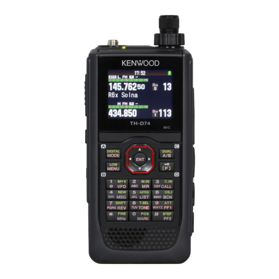
- Page 1 TH-D74A TH-D74E USER MANUAL B5A-1253-00...
-
Page 2: Table Of Contents
1 CONTENTS 1 CONTENTS ............1 FREQUENCY STEP SIZE ..............12-1 FINE TUNING .................12-1 2 BEFORE STARTING ..........2-1 ATTENUATOR (ATT) ...............12-1 3 PREPARATION .............3-1 PROGRAMMABLE VFO ..............12-2 SUPPLIED ACCESSORIES ...............3-1 BEAT SHIFT ...................12-2 INSTALLING THE ANTENNA ............3-1 IF/ DETECT OUTPUT MODE ............12-2 INSTALLING THE BATTERY PACK ...........3-1 FM NARROW .................12-3 INSTALLING ALKALINE BATTERIES ..........3-1... - Page 3 TURNING ON/ OFF THE Bluetooth FUNCTION .......18-1 • JVC KENWOOD Corporation has the right to change or CONNECTING BY THE PAIRED DEVICE LIST .........18-2 improve the product specifications, etc., described in this CONNECTING TO A PC VIA Bluetooth ...........18-3 manual without prior notice.
-
Page 4: Before Starting
2 BEFORE STARTING Thank You We are grateful you decided to purchase this KENWOOD Digital transceiver. The models listed below are covered by this manual. TH-D74A: 144/220/430MHz Tribander (The Americas) TH-D74E: 144/430MHz Dual Bander (Europe) Features This transceiver has the following main features: •... -
Page 5: Preparation
3 PREPARATION SUPPLIED ACCESSORIES To remove the battery pack, lift the release lever to unlock the battery pack. Lift the battery pack away from the transceiver. After carefully unpacking the transceiver, identify the items listed in the table below. We recommend you keep the box and packaging for shipping. -
Page 6: Installing The Belt Clip
If desired, you can install the supplied belt clip to the transceiver. Attach the belt clip firmly using the two supplied M3 x 6 mm binding screws. DC IN jack TH-D74A TH-D74E 3 Plug the charger into an AC wall outlet. • Charging starts and “Charging” appears on the display. -
Page 7: Battery Life
CONNECTING TO A REGULATED POWER SUPPLY Charger Error • While charging, if a problem is detected in the battery, To connect the transceiver to an appropriate regulated DC “Charge Error !!” appears on the display. power supply, use an optional PG-2W DC cable. •... -
Page 8: Getting Acquainted
4 GETTING ACQUAINTED KEY AND CONTROL KNOB OPERATIONS LCD Display SP/MIC Jacks Microphone microSD memory card slot Micro-USB Connector (USB2.0, Type B) DC IN (External power supply) Speaker Jack Press [ ] (1s) to turn the transceiver power ON and OFF. Press and hold [ ] to select a frequency band in VFO mode. - Page 9 [MR] (2) Press [MR] to enter Memory Channel mode. Press [F], [MR] to move to the Memory channel store screen. [CALL] (3) Press [CALL] to select the Call channel. Press [F], [CALL] to store the current operating frequency to the Call channel. [MSG] (4) Press [MSG] to display the APRS Message list.
-
Page 10: Display
DISPLAY Frequency Display Common icon Display Area A Band Display Area B Band Display Area Various function indicator Indicator Description Indicator Description Appears when the Cross tone function is “DCS/ Performs as the S meter when receiving a CTCSS”. signal. Appears when the Cross tone function is Displays the selected power level while “TONE/DCS”. - Page 11 Appears when the key lock is ON. Indicates the battery level. Appears during charging of the battery. Indicates the memory group number. Indicates the Weather Channel. (TH-D74A only.) Appears when the Memory Channel Lockout function is ON. Appears when the Repeater Lockout function is ON.
-
Page 12: Basic Operations
5 BASIC OPERATIONS SWITCHING THE POWER ON/ OFF 2 Change the balance with [ ]/[ ] or [ENC] control. • Band A and B are set to the same volume level (MAX) as a default setting. Pressing [MODE] returns to the Switching the Power ON previous screen without changing the setting. -
Page 13: Selecting A Frequency Band
To adjust the frequency by a larger amount, press [MHz] to Note: enter MHz mode, then rotate the ENC control or use the ◆ 220 MHz band in Band A is used by the TH-D74A only. ]/[ ] keys to adjust the frequency in steps of 1 MHz. Frequency ranges: Press [MHz] again to exit MHz mode and adjust the •... -
Page 14: Adjusting The Squelch
MONITOR TH-D74E When you are receiving while the squelch function is ON, Band Call Channel Memory Name weak signals may become intermittent. VHF (except DV/DR mode) 145.500 MHz (FM) Call VHF (FM) 1 Press and hold [MONI]. VHF(DV/DR mode) 144.8125MHz (DV) Call VHF (DV) •... -
Page 15: Menu Mode
6 MENU MODE Software Key operation Many functions on this transceiver are selected or configured through the Menu instead of physical controls. Software keys ([Back], [OK], etc.) are displayed in the key guide area of various setting screens and other screens. To select or operate the displayed functions, press the MENU ACCESS corresponding keys. -
Page 16: Menu Configuration
Off (AF)/ IF/ Detect FM Narrow FM narrow Off/ On MW/ SW Antenna MW/ SW Antenna ANT connector / Bar Antenna WX Alert Off/ On (TH-D74A only) Weather alert TX/RX - TX TX Inhibit Off/ On TX inhibit Time-out Timer Time-out timer 0.5/ 1.0/ 1.5/ 2.0/ 2.5/ 3.0/ 3.5/ 4.0/ 4.5/ 5.0/ 10.0 [min]... - Page 17 Display Description Setting Values TX/RX - Others QSO Log Off/ On QSO log RX: Check LED Control LED control FM Radio: Uncheck Memory - Memory Channel View List Memory channel list Group Name Memory group name input Up to 16 characters Recall Method All Bands/ Current Band Memory channel recall method...
- Page 18 Minimum time delay between each Turn Time 5 - 60 - 180 [sec] beacon transmission APRS - Waypoint Format NMEA/ MAGELLAN/ KENWOOD Way point format Length Way point name length 6-Char/ 7-Char/ 8-Char/ 9-Char Output Way point output type...
- Page 19 Display Description Setting Values Digital - Digital Squelch Select Type Off/Code Squelch/ Callsign Squelch Select Type Digital Code 00 - 99 Digital Code Digital - GPS Data TX GPS Info. in Frame GPS Information in frame Off/ On $GPGGA/ $GPGLL/ $GPGSA/ $GPGSV/ $GPRMC/ Sentence Sentence $GPVTG...
- Page 20 Off/ On Volume Lock Volume lock Off/ On Configuration - Units Speed, Distance Speed/ Distance mi/h, mile (TH-D74A)/ km/h, km (TH-D74E)/ knots, nm Altitude, Rain feet, inch (TH-D74A)/ m, mm (TH-D74E) Altitude/ Rain Temperature °F (TH-D74A)/ °C (TH-D74E) Temperature Latitude, Longitude dd°mm.mm’/ dd°mm’ss.s”...
-
Page 21: Operating Through Fm Repeaters
Most repeaters use a receive and transmit frequency pair with a standard or non-standard offset (odd-split). In addition, TH-D74A: some repeaters must receive a tone from the transceiver in order to gain access to the repeater. For details, consult your Under 145.100 MHz:... - Page 22 Activating the Tone Function Frequency Frequency Frequency (Hz) (Hz) (Hz) To turn the Tone function on: 118.8 183.5 1 Select your desired band A or B. 67.0 2 Press [TONE] to turn the Tone function On. 123.0 186.2 69.3 • Each time you press [TONE], the selection changes as 127.3 189.9 71.9...
-
Page 23: Transmitting A 1750 Hz Tone
TRANSMITTING A 1750 Hz TONE REVERSE FUNCTION Most repeaters in Europe require that a transceiver transmit After setting a separate receive and transmit frequency, you a 1750 Hz tone. On a TH-D74E, simply pressing [CALL] will can exchange these frequencies using the Reverse function. transmit this tone. -
Page 24: Memory Channel
Priority scan memory Simplex & Parameter Odd-split Repeater Weather channels [A 1] to [A10] (TH-D74A only) Receive frequency CALL channels Transmit frequency 3 Select the channel. Receive frequency step size You can select the channel by inputting the channel Transmit frequency step size number from 0 to 999 by 12 keypad. -
Page 25: Recalling A Memory Channel
Storing Simplex and Standard Repeater Frequencies 1 Select the frequency, mode, etc. 2 Press [F], [MR]. Memory channel registration screen appears on the display. • Press [MODE] to return to the memory channel list menu. 5 Press [A/B]. The specified memory channel is cleared. To clear another memory channel, repeat the procedure from step 3. -
Page 26: Editing Memory Channel
Memory Recall Method 3 Select [Group] and press [A/B]. The memory group selection screen appears. This menu provides you with the option to recall memory channels with stored frequencies in your current frequency band, or all memory channels: 1 Access Menu No. 202. 4 Select any group from group 0 (GRP-0) to group 29 (GRP- 29) and press [A/B]. -
Page 27: Call Channel Memory (Simplex)
CALL CHANNEL MEMORY (SIMPLEX) Editing a CALL Channel Name You can name CALL channel using up to 8 characters. The CALL channel can be used to store any frequency and related data that you will recall often. You may want to 1 Access Menu No. -
Page 28: Memory Shift
3 Select [Clear Group] and press [A/B]. The memory group name is registered and the frequency screen reappears. The clear group selection screen appears. MEMORY SHIFT Shift the contents of a memory channel or CALL channel to VFO. Shifting Memory from the Frequency Screen 4 Select the group to clear. -
Page 29: Scan
9 SCAN Time-Operate Resume Time Scan is a useful feature for hands-off monitoring of your favorite frequencies. Becoming comfortable with all types of Set the hold time for the Time-Operate scan method. Scan will increase your operating efficiency. When a signal is received, scan will pause at that frequency This transceiver provides the following types of scans. -
Page 30: Program Scan
PROGRAM SCAN MHz SCAN Program scan is to scan within the range between the lower MHz scan monitors a 1 MHz segment of the band, using limit frequency and upper limit frequency registered to the current frequency step size. The current 1 MHz digit program scan memory. -
Page 31: Group Link Scan
Locking Out a Memory Channel 2 Select a group link number. When a memory group is already linked, press [A/B] to This function allows you to skip specific memory channel cancel the link. by excluding it from scanning when a memory scan is 3 Press [ENT]. -
Page 32: Priority Scan
PRIORITY SCAN SCAN AUTO BACKLIGHT This function checks the frequency registered to the priority This function turns on the backlight for approximately 2 channel once every three seconds, and displays the priority seconds when scanning is paused. This function works with channel to perform communication at that frequency if all scans. -
Page 33: 10 Ctcss/Dcs/Cross Tone
10 CTCSS/DCS/CROSS TONE CTCSS Frequency Frequency Frequency You may sometimes want to hear calls only from specific (Hz) (Hz) (Hz) persons. The Continuous Tone Coded Squelch System 118.8 183.5 67.0 (CTCSS) allows you to ignore (not hear) unwanted calls from other persons who are using the same frequency. To 123.0 186.2 69.3... -
Page 34: Dcs
3 Press [F], [TONE]. CTCSS Frequency Scan • The current DCS code appears on the display and This function scans through all CTCSS frequencies to identify blinks. the incoming CTCSS frequency on a received signal. You may find this useful when you cannot recall the CTCSS frequency that the other persons in your group are using. -
Page 35: Cross Tone
2 Press [F], [TONE] (1s). “ ” • Scan starts and Scanning blinks on the display. • To quit the scan, press [ ]. • When a DCS code is identified, the identified code appears on the display and blinks. 3 Press [A/B] to program the identified code in place of the currently set DCS code. -
Page 36: Dual Tone Multi-Frequency(Dtmf)
11 DUAL TONE MULTI-FREQUENCY(DTMF) DTMF Hold The keys on the keypad function as DTMF keys; the 12 keys found on a push-button telephone plus 4 additional keys (A, Activate this function to remain in transmit mode, after B, C, D). This transceiver provides 10 dedicated memory beginning to press keys when making a call. -
Page 37: Echolink Memory
EchoLink MEMORY 5 Enter a DTMF code for the channel. When a space is entered, it becomes a “Pause” code. EchoLink allows you to communicate with other amateur radio stations over the internet, using VoIP (voice-over- IP) technology. The EchoLink software program allows worldwide connections to be made between stations, or from computer to station, greatly enhancing your communications capabilities. - Page 38 7 Press [ENT]. EchoLink memory code is stored. • If you want to store another EchoLink memory channel, repeat the procedure from step 2. Transmitting EchoLink Memory 1 Press and hold [PTT]. 2 While transmitting, press [ENT]. • The last called EchoLink DTMF Memory channel name and number appears on the display.
-
Page 39: 12 Other Operations
◆ While in Fine Tuning mode, you cannot change the frequency step size, MHz mode, and MHz Scan. The default on the 220 MHz band is 20 kHz (TH-D74A). The ◆ Simply turning the Fine Tuning function OFF will not change default on the 430 MHz band is 25 kHz. -
Page 40: Programmable Vfo
PROGRAMMABLE VFO BEAT SHIFT If you always check frequencies within a certain range, Since the transceiver uses a microprocessor to control you can set upper and lower limits for frequencies that are various transceiver functions, the CPU clock oscillator’s selectable. For example, if you select 144 MHz for the lower harmonics or image may appear on some spots of the limit and 145 MHz for the upper limit, the tunable range will reception frequencies. -
Page 41: Fm Narrow
◆ Special PC software is required to process IF signal or low-power signal, we recommend using a dedicated external detection signal. JVC KENWOOD does not provide any support antenna tuned to the frequency of the target signal whenever regarding the procedure to connect to a PC or the PC software. -
Page 42: Time-Out Timer
TIME-OUT TIMER SETTING RECEIVING FILTERS Reduce interference and noise in SSB mode, CW mode, and The Time-out Timer limits the duration you transmit. Just AM mode to make the received sound easier to hear. before the transceiver stops the transmitting, a warning beep sounds. -
Page 43: Vox (Voice-Operated Transmission)
VOX (VOICE-OPERATED TRANSMISSION) From the Menu: 1 Access Menu No. 151. VOX eliminates the necessity of manually switching to Transmit mode each time you want to transmit. The transceiver automatically switches to Transmit mode when the VOX circuitry senses that you have begun speaking into the microphone. -
Page 44: Pitch Frequency
VOX on Busy LED CONTROL You can configure the transceiver to force VOX transmission This function turns off the BUSY LED to reduce the even if the transceiver is receiving a signal. consumption of battery power. With the default setting, the BUSY LED is always on when receiving FM radio broadcasts. -
Page 45: Display Illumination
DISPLAY ILLUMINATION Brightness The brightness of the backlight can be set to any of three The display and key illumination can be turned on when, for levels. example, you use the transceiver in a dark location. 1 Access Menu No. 902. Temporary lighting Press [ ] to illuminate the display and keys. -
Page 46: Single Band Display
SINGLE BAND DISPLAY Note: ◆ When selecting [GPS(Altitude)] or [GPS(GS)], set the built-in You can changes the displayed information during single GPS to [ON]. band display. Selecting the Information to Display METER TYPE 1 Access Menu No. 904 This function changes the design of the S/RF meter. 1 Access Menu No. -
Page 47: Audio Equalizer (Tx/Rx)
AUDIO EQUALIZER (TX/RX) RX Equalizer Change the received voice frequency characteristic. The This function turns on or off the equalizer setting for frequency characteristic of the received voice can be set to transmission and receiving. the below levels for each of five frequency points. 1 Access Menu No. -
Page 48: Beep Volume
BEEP VOLUME BATTERY LEVEL You can set the beep volume. You can verify the battery capacity while in Menu mode. 1 Access Menu No. 915. 1 Access Menu No. 922. 2 Select among from [Level 1] to [Level 7]. Note: ◆... -
Page 49: Programmable Function Keys
PROGRAMMABLE FUNCTION KEYS Setting the Transceiver PF Keys There are 2 PF (Programmable Function) keys on the Transceiver PF Keys and Microphone PF keys transceiver front panel: PF1 and PF2. You can assign your Function name Description own desired functions to these 2 keys. Recording Recording start/ stop 1 Access Menu No. -
Page 50: Key Lock
VOLUME LOCK KEY LOCK This function locks the volume so that it cannot be changed The Key Lock function ensures that your transceiver settings inadvertently. will remain unchanged if you accidentally press a key. 1 Use the [VOL] control to set the volume level you wish to To turn Key Lock On or Off, press [F] (1s). -
Page 51: Output Destination Interface (Usb/Bluetooth)
Setting the Altitude, Rainfall OUTPUT DESTINATION INTERFACE (USB/ Bluetooth) 1 Access Menu No. 971. Set the interface to use for each of the following applications. Select [USB] or [Bluetooth]. • GPS data (NMEA) output • APRS packet output • KISS mode (input and output) •... -
Page 52: Selecting A Language
Setting the Data Band (Digital) Interface VERIFYING THE FIRMWARE VERSION 1 Access Menu No. 984. You can verify your current transceiver firmware version. 1 Access Menu No. 991. The current firmware version is displayed. 2 Select [USB] or [Bluetooth]. • The following describes the operation for each application when the output destination interface specifications are TRANSCEIVER RESET duplicated. -
Page 53: 13 Gps
13 GPS BUILT-IN GPS FUNCTION ON/ OFF Latitude Entry 1 Access Menu No. 400 The north/ south latitude is entered. Longitude Entry 2 Select [On] or [Off]. [On]: Turns on the built-in GPS function. [Off]: Turns off the built-in GPS function. •... - Page 54 Displaying Position Information Built-in GPS Operation Mode When the built-in GPS receiver is On, pressing [F], [MARK] 1 Access Menu No. 403. will display “Latitude/longitude, time, altitude, heading, speed”, then press to cycle the display between “Latitude/longitude, time, altitude, heading, speed” ➡ “Target point distance, Travel direction”...
- Page 55 Key operations in [GPS satellite information] GPS Data PC Output Key Name Operation Turn this function on when you want to send the built-in GPS receiver data (NMEA) from the Micro-USB connector or Switches to [Target point distance and Target Bluetooth.
-
Page 56: Mark Function
MARK FUNCTION You can register up to 100 points with the location’s latitude, longitude, altitude, time, name, and icon in the Position Memory List. 1 Press [MARK] (1s). The position memory store screen appears. • When pressing [F], the North Up display (displays North as the top) changes to the Heading Up display (displays the current travel direction as the top) or vice- versa. - Page 57 Editing the Position (Latitude and Longitude) Key Name Operation 1 Select [Position] and press [A/B]. ] or Changes the item. The mode changes to the latitude and longitude edit mode. [ENC] [ENT] Confirms the editing. [MODE] Cancels editing and returns to the previous screen. Sorting Position Memory List 1 Press [MARK].
-
Page 58: Target Point
When pressing [F] while the target point distance Track Log started date. and target direction are displayed, the North Up display Example: TH-D74A:05122016_124705.nme (File for which track (displays North as the top) changes to the Heading Up logging started at 12:47:05 on May 12 2016.) display (displays the current travel direction as the top) or TH-D74E:12052016_124705.nme (File for which track logging... - Page 59 Selecting the Track Log Acquisition Type Clearing the Track Log You can set the conditions for saving portable Track Clear a Track Log saved in a microSD memory card. information as GPS Logger. 1 Access Menu No. 411. You can change the settings for travel speed, etc. 1 Access Menu No.
-
Page 60: Aprs
APRS network. Home (/-) Yagi@QTH (/y) My Callsign KENWOOD (\K) Program your Callsign using a maximum of 9 alphanumeric characters including SSID (Secondary Station IDentifiers) RADIO (\Y) such as -7, -9, or -14. Unless you program a Callsign, you cannot transmit APRS packets. - Page 61 APRStt (\A) Balloon (/O) (/.) Glider (/g) Triangle (\n) Helicopter (/X) Small Circle (\o) Aircraft (/') Red Dot (//) Large Aircraft (/^) Big Question Mark (\.) Shuttle (/S) Satellite (\S) Overlay Character Setting Rover (/p) For example, to set the Radio icon to the letter “K”, select Eyeball (/E) “Radio”...
-
Page 62: Position Comment
POSITION COMMENT STATUS TEXT The APRS data which you transmit always includes one Status text is another comment to transmit with position of the 15 predetermined position comments. Select an data. Unlike a position comment, you can make any desired appropriate comment depending on your situation. - Page 63 Setting APRS Data Communication ON Note: ◆ The APRS programs for PCs have entry fields for a position Press [F], [LIST] to enter APRS mode. comment and status text. The data entered to these two fields are transmitted as separate packets. This transceiver, however, Each time a new APRS packet is received, the frequency includes both of a position comment and status text in one packet display is interrupted to show information as below.
-
Page 64: Station List
STATION LIST Note: ◆ When data from the 101st station is received, the oldest data in This transceiver is capable of receiving and storing APRS memory is replaced by that data. data received from up to 100 stations in memory. You can ◆... - Page 65 Page 3: b Situation in Page 1: (Mobile station) Display Description Fixed Fixed station Weather Weather station Moving Mobile station GOOD/RMC LAST/RMC GPS Tracker • GOOD: in GPS positioning GOOD/GGA a Direction and moving direction of the other station LAST: in a non-positioning b Moving direction of my station LAST/GGA •...
- Page 66 Cursor Control Sort Function Select a cursor control setting for station list screen. This function allows you to sort the station list according to the Callsign, date time, or distance. 1 Press [MODE] to change the cursor control type to [Followed] or [Fixed].
- Page 67 Only Weather Stations are displayed. Mobile Only Mobile Stations are displayed. Object Only Object Stations are displayed. Only KENWOOD TH-D74, TH-D72, TH- KENWOOD D7, TM-D700, TM-D710G, TM-D710, and RC-D710 Stations are displayed. Only Navitra Stations starting from 5 Press [A/B].
-
Page 68: Aprs Message Functions
APRS MESSAGE FUNCTIONS Last page: Receiving a Message Each time a proper message is received, the frequency display is interrupted to show information as below: a TX Message status b Meaning indicator c Receiving message/sending message d Callsign e Message f Receive date g Line number h Message group i Receive time •... - Page 69 Transmitting a Message 6 Select [Send] and press [A/B] to send the message. You can select the following items other than [Send], 1 Press [MSG]. [Reply], [Edit], and [New] in message list Menu. The message list appears on the display. [Re-TX]: Send the message again.
-
Page 70: Programming A Packet Path
PROGRAMMING A PACKET PATH 3 Select the relay step number for the <Total Hops> setting. Select the packet path type from [New-N], [Relay], [Region], [Others1], [Others2], or [Others3]. When you press [A/B], the < > indicator appears on the right side of the packet path type, showing the current used information. -
Page 71: Setting Internal Tnc
DCD Sense You can also select the method for inhibiting the built-in TNC from transmitting. 1 Access Menu No. 507. • A Packet path is the digipeat route of the packet data sent from My station. For example, if you want your packet to take the [W5DJY-1] >... -
Page 72: Aprs Lock
APRS LOCK at intervals of the period selected in < Initial Interval >. This function prevents accidentally changing the data band 2 To switch the function OFF, press [BCN] again. frequency or accidentally transmitting on the data band by [SmartBeaconing]: pressing [PTT]. -
Page 73: Setting Beacon Information
Decay Algorithm When jointly using a Decay Algorithm, if the speed is 1 knot or slower, a Decay Algorithm pattern is used for This function continuously extends the packet transmission transmitting, but if the speed is 3 knots or faster, it changes interval in the case that there is no change of position to Proportional Pathing. -
Page 74: Object Functions
OBJECT FUNCTIONS Latitude/Longitude Setting the Object Information. 1 Access Menu No. 516. 6 Enter a Latitude and Longitude and press [A/B]. Icon 2 Select [Object1], [Object2], or [Object3] and press [ENT]. • When you press [A/B], the < > indicator appears on the right side of the object item, showing the current used information. -
Page 75: Qsy Function
QSY FUNCTION QSY Transmission Operation This function embeds the voice channel frequency, Wide/ The QSY function uses AFRS (Automatic Frequency Narrow status, tone, shift, and offset information in the first Reporting System) to report a frequency on which voice character of the status text. communications can be established. -
Page 76: Setting Smartbeaconing Tm
Operation When Receiving a QSY Slow Rate When QSY (frequency) information is received, the station list Low speed transmission interval time. appears with the verified frequency. 1 Access Menu No. 531. 1 Select [Tune], and press [A/B]. 2 Select from [1] to [100] minutes. •... -
Page 77: Setting Way Point
Operates [MAGELLAN]: The data using the " $PMGNWPL" format. (Only when the set normally (Transmission <High Speed> ≧ <Low [KENWOOD]: The data using the " $PKWDWPL" format. Interval = <Fast Speed>) Rate> x <High Speed> ÷ Speed) Way Point Length Will not Below the <Low Speed>... -
Page 78: Setting Packet Filter
SETTING PACKET FILTER STORING USER PHRASES This function (clipboard image) allows you to paste phrases into the APRS message compilation mode. You can create Position Limit up to 20 phrases each of which can consist of up to 32 characters. If APRS is popular in your area, you may receive too many 1 Access Menu No. -
Page 79: Setting Notification Sound
Reply To Callsign SETTING NOTIFICATION SOUND When there is a message you would like to reply to for the specific Callsign, preset that Callsign for automatic RX Beep Type responses. 1 Access Menu No. 562. This transceiver beeps each time it receives any type of APRS packets. -
Page 80: Setting Display
SETTING DISPLAY PC OUTPUT This function outputs data from the USB port/ Bluetooth after receiving packet or waypoint data from the APRS data Display Area communications. Use this function to verify the received data from the transceiver. Selects the Display area. 1 Access Menu No. -
Page 81: Voice Alert
VOICE ALERT PROGRAMMING MESSAGE GROUP CODE This function will notify another station as to whether or not Use a message group code to exchange messages only they are within communications range by emitting beacon among your group members. With one or more message tones. -
Page 82: 15 Built-In Kiss Tnc
USB (up to 12 Mbps) or Bluetooth (up to 128 Kbps). Packets to be transmitted still remain in the buffer. ◆ Depending on the usage condition of the USB apparatus, saved content may be lost. JVC KENWOOD does not take Note: responsibility for damages or lost content. -
Page 83: 16 D-Star
16 D-STAR D-STAR INTRODUCTION MY CALLSIGN • In the original D-STAR (Digital Smart Technologies for Set your Callsign to the transceiver in DV/DR mode. Amateur Radio) plan, JARL envisioned a system of Transmission in DV/DR mode will not be possible if you do repeaters grouped together into Zones. -
Page 84: Digital Function Menu
DIGITAL FUNCTION MENU SIMPLEX CALL This menu switches the functions to use for operation in Simplex call can be used for direct communication between a digital mode. pair of transceivers without using a repeater. Simplex call can be operated only in DV mode. How to Use the Digital Function Menu 1 Press [MODE] to enter DR mode. -
Page 85: Local Area Call
LOCAL AREA CALL Setting the Local CQ (TO) 1 Press [ ] (1s). A local area call (local CQ) is the output of a CQ through only one repeater. A call can be made by setting a local CQ to The destination selection screen appears. -
Page 86: Gateway Call
GATEWAY CALL CALLSIGN DESIGNATION A gateway call can be made by setting the area repeater to A call by Callsign designation can be made by setting the output the CQ to [TO] and pressing [PTT]. Callsign of the other party to [TO] and pressing PTT. A call to the specific station is relayed automatically to the last A gateway CQ is the output of a CQ to an area that is accessed repeater, so a call can be made without knowing... -
Page 87: Direct Reply
Sorting the Callsign AUTO REPLY FUNCTION You can sort the Callsign list. This function is to set automatically the Callsign of the other station and reply when a signal to your Callsign is received. 1 Press [MODE] in the Callsign list selection screen. 1 Select [Auto Reply] in the Digital Function Menu. -
Page 88: Tx Messages
Displaying the RX History 4 Select a number for registration and press [ENT]. The TX messages is selected 1 Access Menu No. 600. Each press of [PTT] transmits the selected message. TX HISTORY Up to 20 entries can be stored in TX history for signals transmitted in DV/DR mode. -
Page 89: Setting The Access Repeater (From)
Setting the Destination Repeater (TO) Setting by Direct Input 1 Press [ ] (1s). You can set the repeater by directly inputting the Callsign of the repeater. The destination selection screen appears. This screen also 1 Press (1s). appears when selecting [Destination Select] in the Digital Function Menu. -
Page 90: Checking The Callsign Setting
Setting by Local CQ [Repeater Info.]: You can send the repeater information command. Select [Repeater Info.] and press [ENT]. Then 1 Press [ ] (1s). [_______I] is set to [TO]. Then press [PTT] to transmit the repeater information command. After releasing [PTT], The destination selection screen appears. -
Page 91: Displaying The Repeater Details
DISPLAYING THE REPEATER DETAILS Data TX End Timing This function is to set the delay time until return from fast You can check the details information of the repeater. data TX to RX in accordance with the TX timing of the PC 1 Select [Repeater Detail] in the Digital Function Menu. -
Page 92: Rx Afc
RX AFC BK (BREAK) CALL BK (Break) Call is used to simultaneously call two stations This function is to correct a slight frequency offset of the that are communicating by the Callsign squelch in DV/DR received signal to achieve frequency stability. mode. -
Page 93: Callsign Squelch/ Code Squelch
GPS Sentence Note: ◆ This setting is canceled when the power is switched OFF. Select the sentence to transmit location information when operating in DV mode. The GPS sentences that can be used with the transceiver are 6 kinds of [GGA], [GLL], [GSA], CALLSIGN SQUELCH/ CODE SQUELCH [GSV], [RMC], and [VTG], but only four of them can be set at the same time. -
Page 94: Rx Break-In Display
RX BREAK-IN DISPLAY RX Break-In Display Hold Time This function is to select the hold time to display the Break- This function is to display information received from other In after RX ends. When the set time elapses, the Break-In station in a Break-In screen. -
Page 95: Standby Beep
STANDBY BEEP ◆ If there is no more than one repeater registered in the repeater list, a repeater scan can not be performed. This function is to notify with a beep sound that transmission has ended when a D-STAR signal is received. REPEATER SCAN LOCKOUT 1 Access Menu No. -
Page 96: Repeater List
REPEATER LIST Repeater List Editing Menu Up to 1,500 repeaters can be registered in the repeater list. Editing Menu Operation Name editing Edit the repeater name. screen Displaying the Repeater List Sub Name editing Edit the repeater sub-name. 1 Access Menu No. 210. screen World region selection screen appears. -
Page 97: 17 Usb
[Mass Storage]: The transceiver enters mass storage COM port driver from the following URL. mode. You can access the microSD memory card of the http://www.kenwood.com/i/products/info/amateur/software_ transceiver from a PC. The transceiver will be displayed as download.html a removable disk on the PC. -
Page 98: Bluetooth
18 Bluetooth ® 1 Access Menu No. 930 to turn on the Bluetooth function. If you purchase a commercially available headset that is compatible with Bluetooth, you can connect the transceiver 2 Place the headset (device to be connected) near the and headset to perform communication wirelessly. -
Page 99: Connecting By The Paired Device List
2 Select the device to be connected. Entering the PIN Code When connecting the device that is already selected, When searching for the device, you may be requested to proceed to step 3. enter the PIN code depending on the device to be connected. If you select the device to be connected and press [ When Requested to Enter the PIN Code the Bluetooth device information screen appears. -
Page 100: Connecting To A Pc Via Bluetooth
3 Select [Clear] and press [ENT]. 3 Configure the settings on the PC. The device clear confirmation screen appears. Configure the settings according to the instructions displayed on the PC. 4 Press [A/B] to return to the frequency screen. Note: ◆... - Page 101 Bluetooth Auto Connect This function is for automatically connecting with the Bluetooth device used last time when the power of the transceiver is turned on. 1 Access Menu No. 936. 2 Select [On] or [Off]. [On]: Turns ON the auto connect function. [Off]: Turns OFF the auto connect function.
-
Page 102: 19 Microsd Memory Card
SETTING microSDHC 16 GB CALLSIGN_LIST: Stores Callsign 32 GB lists. • Regardless of the above table, JVC KENWOOD does not RPT_LIST: Stores repeater lists. guarantee the operation of all microSD memory card • The operation of a microSD formatted with memory card DATA: Stores configuration data. -
Page 103: Formatting A Microsd Memory Card
Removing (Unmounting) a microSD Memory Card Saving the Configuration Data + Voice message When removing a microSD memory card, be sure to perform 1 Access Menu No. 801. the operation to safely remove (unmount) it. Saving begins. When saving is completed, the data writing completed screen appears. -
Page 104: Clearing The Saved File
The repeater list appears. 2 Select the file and press [A/B]. The file clear confirmation screen appears. 2 Select [Data For TH-D74A], [Data For TH-D74E], or [Data For TH-D74] and press [A/B]. [Data For TH-D74A]: Repeater lists mainly used in North America. -
Page 105: Displaying The Microsd Memory Card Information
DISPLAYING THE microSD MEMORY CARD 2 Select [On]. Recording begins when PTT is pressed. INFORMATION [Off]: Does not record the communication history. 1 Access Menu No. 840. [On]: Recording the communication history. The microSD memory card information screen appears. Stored files are named as follows. Pressing [MODE] returns to the previous screen. -
Page 106: 20 Recording
When the file being recorded exceeds 2 GB, OPERATION OF THE AUDIO FILE recording continues with a new file. • Recording files are named as follows. Example: 12202016_132051.wav (TH-D74A) Playing Audio Files 20122016_132051.wav (TH-D74E) 1 Access Menu No. 300. - Page 107 Clearing Audio Files 1 Access Menu No. 300. The recording file list appears. 2 Select the file. 3 Press [MENU]. The recording file list menu appears. 4 Select [Clear] and press [A/B]. The recording file clear confirmation screen appears. 5 Press [A/B]. The file is cleared and the recording file list reappears.
-
Page 108: 21 Fm Radio
21 FM RADIO Frequency Direct Entry (Direct Station Selection) The transceiver can receive FM radio broadcasts. You can listen to FM radio while simultaneously monitoring two 1 Press [ENT]. signals as well as while waiting for a CQ or a call from an acquaintance, or waiting for an APRS call. - Page 109 3 Select the channel and press [ENT]. 4 Select [Clear Memory] and press [A/B]. The FM radio station is registered and the FM radio The FM radio memory clear confirmation screen appears. memory channel list appears. 5 Press [A/B]. 4 Press The FM radio station is cleared, and the FM radio memory channel list menu reappears.
- Page 110 Memory Shift 5 Enter characters. Copy the frequency of a broadcast station from the FM radio memory channel list to VF0. 1 Access Menu No. 710. The FM radio memory channel list appears. 6 Press [ENT]. The broadcast station name is registered. 2 Select the Channel.
- Page 111 FM Radio Auto Mute Return Time When a signal is received or transmitted in band A or B while listening to a radio broadcast in FM radio mode, the reception sound of the radio broadcast is muted. When a signal is no longer received in band A or B or after transmission is completed, the transceiver automatically returns to FM radio mode after a period of time has lapsed without any operation...
-
Page 112: 22 Voice Message Memory
22 VOICE MESSAGE MEMORY 6 Release [PTT]. The transceiver can record and transmit voice messages in up to 4 channels. This is a convenient function when Recording stops and the voice message is written. transmitting fixed voice messages. Note ◆ Recording is possible for 30 seconds only with channel 1. Recording is possible for 15 seconds with channels 2 to 4. -
Page 113: Sending Voice Messages
SENDING VOICE MESSAGES Repeat Playback Interval Set the repeat playback interval for playing and sending Send the message of a recorded voice message channel. repeatedly. 1 Access Menu No. 310. 1 Access Menu No. 310. The voice message list appears. The voice message list appears. -
Page 114: Clearing Voice Messages
CLEARING VOICE MESSAGES 1 Access Menu No. 310. The voice message list appears. 2 Select the channel to clear. 3 Press [MENU]. The voice message list menu appears. 4 Select [Clear] and press [A/B]. The voice message clear confirmation screen appears. 5 Press [A/B]. -
Page 115: 23 Voice Guidance
23 VOICE GUIDANCE Voice Guidance Volume This function is to play a voice guidance to notify you of the frequency, memory channel information, and other operating This function is to set the volume level of the voice guidance. status shown on the display. 1 Access Menu No. - Page 116 Voice Guidance (Auto1/Auto2) Voice guidance in Auto1/ Auto2 is automatically announced based on the following operations or status. Operation or status Guidance Change to VFO mode "VFO" + Frequency Change to Memory Channel mode "Memory" + Channel number Change to Call mode "C"...
- Page 117 Operation or status Guidance Menu mode Menu mode startup: "Menu" + item number Selecting Menu item: Menu item number Selecting setting value: setting vale Character entry Entering or selecting characters: Entered or Selected characters Selecting half-width alphanumeric characters: "Selection 1" Moving Cursor: Character on the cursor Clearing characters: "Clear"...
- Page 118 Voice Guidance (Manual) Voice guidance below is manually announced based on the following status. Status Guidance Frequency Screen VFO: Operation band + "VFO" + Mode + Frequency + Transmit output power VFO and DV mode: Operation band + "VFO" + "T" + Callsign + Mode + Frequency + Transmit output power DR mode: Operation band + "DR"...
- Page 119 4 Voice guidance for operation band means as follows. Group number Guidance "A" "B" FM Radio Mode "R" 5 Voice guidance for transmit output power band means as follows. Group number Guidance "High" "Medium" "Low" "EL" None (FM Radio Mode) None 23-5...
-
Page 120: Weather Alert (Th-D74A Only)
24 WEATHER ALERT (TH-D74A ONLY) WEATHER CHANNEL SCAN The Weather Alert is available only in the USA and Canada. When activated, this function will check for a received NOAA The memory channel only for the weather alert is scanned. 1050 Hz tone. When the tone is received, the weather alert tone will sound. -
Page 121: Wireless Control (Th-D74A Only)
25 WIRELESS CONTROL (TH-D74A ONLY) CONTROL OPERATION If you also have a KENWOOD multi-band mobile transceiver, you can control one of its bands by sending DTMF tones from 1 Press and hold [PTT]. this handy transceiver. You will find this function useful when you want to control your mobile transceiver from a location 2 While transmitting, press [ENT]. -
Page 122: 26 Options
26 OPTIONS The following options are available for use with this transceiver. Model Name Name KNB-75L Li-ion Battery (STD, 7.4 V, 1800 mAh) KNB-74L Li-ion Battery (Slim, 7.4 V, 1100 mAh) KSC-25LS Rapid Charger KBP-9 Battery Case SMC-32 Speaker Microphone SMC-33 Speaker Microphone SMC-34... -
Page 123: 27 Maintenance
You may return this product for service to the authorized KENWOOD dealer from whom you purchased it, or any authorized KENWOOD service center. Please do not send subassemblies or printed circuit boards; send the complete product. -
Page 124: Troubleshooting
TROUBLESHOOTING The problems described in this table are commonly encountered operational malfunctions and are usually not caused by circuit failure. Problem Probable Cause Corrective Action Power is not turned on when using Battery voltage is low. Recharge the battery pack or replace the AAA alkaline Li-ion battery pack or AAA alkaline batteries with new ones. - Page 125 Problem Probable Cause Corrective Action Received signals are not properly Wrong settings for signal format Try changing to other modes. demodulated. (Demodulation mode). When receiving sound is distorted in Set the ATT function to ON. AM/SSB/CW, the receiving signal is too strong.
-
Page 126: 28 Specifications
GENERAL Frequency Range Band-A TX: 144 - 148 (TH-D74A), 144 - 146 (TH-D74E), 222 - 225 (TH-D74A), 430 - 450 (TH-D74A), 430 - 440 (TH-D74E) MHz 136 - 174, 216 - 260 (TH-D74A only), 410 - 470 MHz Band-B RX: 0.1 - 76, 76 - 108 MHz (WFM) - Page 127 Amateur Band FM 12dB SINAD FM/ NFM 144 MHz 0.18/ 0.22 uV 0.19/ 0.24 uV FM/ NFM 220 MHz (TH-D74A only) 0.18/ 0.22 uV 0.20/ 0.25 uV FM/ NFM 430 MHz 0.18/ 0.22 uV 0.20/ 0.25 uV PN9/GMSK 4.8kbps, BER 1% 144 MHz (TH-D74A) 0.22 uV...
- Page 128 TH-D74A/ TH-D74E SPECIFICATIONS Bluetooth Version, Class Version 3.0, Class 2 Output Power -6 < Pav < 4 dBm Modulation Characteristics 140 ≦ ⊿f 1avg ≦ 175 kHz Initial Carrier Frequency -75 ≦ fo ≦ +75 kHz Carrier Frequency Drift ±25 kHz (One Slot packet) ±40 kHz...
- Page 129 © 2016...