Table of Contents
Advertisement
FILE NO. SVM-16041
SERVICE MANUAL
AIR-CONDITIONER
(MULTI TYPE)
INDOOR UNIT
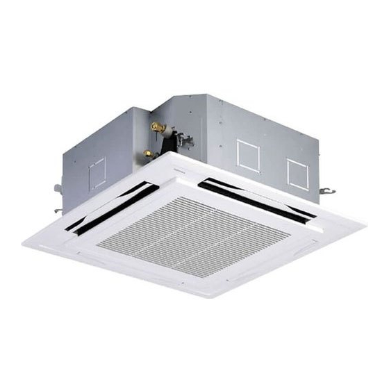
<4-way cassette type>
MMU-AP0094HP1-E (TR)
MMU-AP0124HP1-E (TR)
MMU-AP0154HP1-E (TR)
MMU-AP0184HP1-E (TR)
MMU-AP0244HP1-E (TR)
MMU-AP0274HP1-E (TR)
MMU-AP0304HP1-E (TR)
MMU-AP0364HP1-E (TR)
MMU-AP0484HP1-E (TR)
MMU-AP0564HP1-E (TR)
April, 2016
Advertisement
Table of Contents

Related Manuals for Toshiba MMU-AP0094HP1-E


Summary of Contents for Toshiba MMU-AP0094HP1-E
-
Page 1: Service Manual
FILE NO. SVM-16041 SERVICE MANUAL AIR-CONDITIONER (MULTI TYPE) INDOOR UNIT <4-way cassette type> MMU-AP0094HP1-E (TR) MMU-AP0124HP1-E (TR) MMU-AP0154HP1-E (TR) MMU-AP0184HP1-E (TR) MMU-AP0244HP1-E (TR) MMU-AP0274HP1-E (TR) MMU-AP0304HP1-E (TR) MMU-AP0364HP1-E (TR) MMU-AP0484HP1-E (TR) MMU-AP0564HP1-E (TR) April, 2016... -
Page 2: Table Of Contents
FILE NO. SVM-16041 Original instruction Adoption of New Refrigerant This Air Conditioner is a new type which adopts a new refrigerant HFC (R410A) instead of the conventional refrigerant R22 in order to prevent destruction of the ozone layer. CONTENTS SAFETY CAUTION ........3 1. -
Page 3: Safety Caution
• The qualified service person is a person who installs, repairs, maintains, relocates and removes the air conditioners made by Toshiba Carrier Corporation. He or she has been trained to install, repair, maintain, relocate and remove the air conditioners made by Toshiba Carrier Corporation... - Page 4 FILE NO. SVM-16041 Definition of Protective Gear When the air conditioner is to be transported, installed, maintained, repaired or removed, wear protective gloves and ‘safety’ work clothing. In addition to such normal protective gear, wear the protective gear described below when undertaking the special work detailed in the table below.
-
Page 5: Warning Indications On The Air Conditioner Unit
FILE NO. SVM-16041 Warning Indications on the Air Conditioner Unit [Confirmation of warning label on the main unit] Confirm that labels are indicated on the specified positions If removing the label during parts replace, stick it as the original. Warning indication Description WARNING WARNING... -
Page 6: Precautions For Safety
FILE NO. SVM-16041 PRECAUTIONS FOR SAFETY The manufacturer shall not assume any liability for the damage caused by not observing the description of this manual. DANGER Before carrying out the installation, maintenance, repair or removal work, be sure to set the circuit breaker for both the indoor and outdoor units to the OFF position. - Page 7 FILE NO. SVM-16041 WARNING Before starting to repair the air conditioner, read carefully through the Service Manual, and repair the air conditioner by following its instructions. Only qualified service person (*1) is allowed to repair the air conditioner. Repair of the air conditioner by unqualified person may give rise to a fire, electric shocks, injury, water leaks and / or other problems.
- Page 8 FILE NO. SVM-16041 Do not modify the products. Do not also disassemble or modify the parts. It may cause a fire, electric shock or injury. Prohibition of modification. When any of the electrical parts are to be replaced, ensure that the replacement parts satisfy the specifications given in the Service Manual (or use the parts contained on the parts list in the Service Manual).
- Page 9 FILE NO. SVM-16041 After repair work, surely assemble the disassembled parts, and connect and lead the removed wires as before. Perform the work so that the cabinet or panel does not catch the inner wires. If incorrect assembly or incorrect wire connection was done, a disaster such as a leak or fire is caused Assembly / at user’s side.
- Page 10 FILE NO. SVM-16041 When the service panel of the outdoor unit is to be opened in order for the compressor or the area around this part to be repaired immediately after the air conditioner has been shut down, set the circuit breaker to the OFF position, and then wait at least 10 minutes before opening the service panel.
-
Page 11: Declaration Of Conformity
FILE NO. SVM-16041 Declaration of Conformity Manufacturer: TOSHIBA CARRIER (THAILAND) CO., LTD. 144 / 9 Moo 5, Bangkadi Industrial Park, Tivanon Road, Tambon Bangkadi, Amphur Muang, Pathumthani 12000, Thailand Authorized Representative / Nick Ball TCF holder: Toshiba EMEA Engineering Director Toshiba Carrier UK Ltd. -
Page 12: Specifications
FILE NO. SVM-16041 Specifications Sound Pressure level (dBA) Weight (kg) Model Main unit (Ceiling panel) Cooling Heating MMU-AP0094HP1-E (TR) 18 (4) MMU-AP0124HP1-E (TR) 18 (4) MMU-AP0154HP1-E (TR) 20 (4) MMU-AP0184HP1-E (TR) 20 (4) MMU-AP0244HP1-E (TR) 20 (4) MMU-AP0274HP1-E (TR) 20 (4) -
Page 13: Safety Caution Concerned To New Refrigerant
FILE NO. SVM-16041 • New Refrigerant (R410A) This air conditioner adopts a new HFC type refrigerant (R410A) which does not deplete the ozone layer. 1. Safety Caution Concerned to New Refrigerant The pressure of R410A is high 1.6 times of that of the former refrigerant (R22). Accompanied with change of refrigerant, the refrigerating oil has been also changed. - Page 14 FILE NO. SVM-16041 4. Tools (1) Required Tools for R410A Mixing of different types of oil may cause a trouble such as generation of sludge, clogging of capillary, etc. Accordingly, the tools to be used are classified into the following three types. 1) Tools exclusive for R410A (Those which cannot be used for conventional refrigerant (R22)) 2) Tools exclusive for R410A, but can be also used for conventional refrigerant (R22) 3) Tools commonly used for R410A and for conventional refrigerant (R22)
-
Page 15: Construction Views (External Views)
FILE NO. SVM-16041 1. CONSTRUCTION VIEWS (EXTERNAL VIEWS) MMU-AP0094HP1* , AP0124HP1* 1000 or more 860 to 910 Ceiling open dimension An obstacle 1000 or more The space that is necessary for equipping and service 300 or less Take-in port of wiring Bottom face of ceiling Indoor unit Bottom face of ceiling... -
Page 16: Mmu-Ap0154Hp1
FILE NO. SVM-16041 MMU-AP0154HP1* , AP0184HP1* 860 to 910 Ceiling open dimension 1000 or more An obstacle 1000 or more The space that is necessary for equipping and service 300 or less Take-in port of wiring Bottom face of ceiling Indoor unit Bottom face of ceiling Drain upstanding size... -
Page 17: Mmu-Ap0244Hp1
MMU-AP0244HP1*, AP0274HP1*, AP0304HP1* FILE NO. SVM-16041 860 to 910 Ceiling open dimension 1000 or more An obstacle 1000 or more The space that is necessary for equipping and service 300 or less Take-in port of wiring Bottom face of ceiling Indoor unit Bottom face of ceiling Drain upstanding size... -
Page 18: Mmu-Ap0364Hp1
FILE NO. SVM-16041 MMU-AP0364HP1*, AP0484HP1*, AP0564HP1* 1000 or more 860 to 910 Ceiling open dimension An obstacle 1000 or more The space that is necessary for equipping and service 300 or less Take-in port of wiring Bottom face of ceiling Indoor unit Bottom face of ceiling Refrigerant pipe connecting port... -
Page 19: Wiring Diagram
FILE NO. SVM-16041 2. WIRING DIAGRAM – 19 –... -
Page 20: Parts Rating
FILE NO. SVM-16041 3. PARTS RATING 3-1. Part Rating MMU- Model AP009 AP012 AP015 AP018 AP024 AP027 AP030 Fan motor SWF-230-60-2R Motor for horizontal grille MSBPC20F04 Pulse motor EFM-MD12TF-1 EFM-25YGTCTH-2 EFM-40YGTCTH-2 Pulse motor valve Lead wire length : 328 mm Vinyl tube TA sensor TC1 sensor Ø4 size lead wire length : 1000 mm Vinyl tube (Blue) -
Page 21: Refrigerating Cycle Diagram
FILE NO. SVM-16041 4. REFRIGERATING CYCLE DIAGRAM Liquid side Gas side Strainer Capillary tube Air heat exchanger at indoor side Pulse Motor Valve (PMV) Strainer Sensor (TCJ) Sensor (TC2) Sensor (TC1) Sensor Fan motor (TA) Functional part name Functional outline Pulse Motor Valve (Connector CN082 (6P): Blue) 1) Controls super heat in cooling operation... -
Page 22: Control Outline
FILE NO. SVM-16041 5. CONTROL OUTLINE 5-1. Control Specifications Item Outline of specifications Remarks When power 1) Distinction of outdoor unit supply is reset When the power supply is reset, the outdoors are distinguished and the control is selected according to the distinguished result. - Page 23 FILE NO. SVM-16041 Item Outline of specifications Remarks Room temp. 2) Using the CODE N . 06, the setup temperature in heating Shift of suction control operation can be corrected. temperature in heating (Continued) operation Setup data Setup temp. correction +0°C +2°C +4°C...
- Page 24 FILE NO. SVM-16041 Item Outline of specifications Remarks Air speed 1) Operation with (HH), (H), (L) or [AUTO] mode is carried HH > H+ > H > L+ > L > UL selection out by the command from the remote controller. 2) When the air speed mode [AUTO] is selected, the air speed varies by the difference between Ta and Ts.
- Page 25 FILE NO. SVM-16041 Item Outline of specifications Remarks Air speed selection Selection of high ceiling type CODE No. : (Continued): [5d] or selection of high ceiling on P .C. board SW501 Standard Type 1 Type 3 Type 6 CODE No. [5d] 0000 0001...
- Page 26 FILE NO. SVM-16041 Item Outline of specifications Remarks Freeze prevention 1. In all cooling operation, the air conditioner operates TC1: Temperature of indoor control (Low temp. as de-scribed below based upon temp. detected by heat exchanger sensor release) TC1, TC2 and TCJ sensors. •...
- Page 27 FILE NO. SVM-16041 Item Outline of specifications Remarks Recovery control The indoor unit which is under STOP/Thermo-OFF • The indoor unit which is for heating status or which operates in [FAN] mode performs the under thermo-OFF (COOL) refrigerant (Oil) following controls when it received the heating status or which operates in refrigerant (Oil) recovery signal from the outdoor unit.
- Page 28 FILE NO. SVM-16041 Item Outline of specifications Remarks < READY> Displayed on the remote controller • < READY> display Display of [READY] 1) When the following check codes are indicated No display for wireless [HEAT READY] type remote controller • Open phase of power supply wiring [P05] was detected. •...
- Page 29 FILE NO. SVM-16041 Item Outline of specifications Remarks Louver control: 1) Louver position setup The louver position at horizontal discharge • When the louver position is changed, the position moves position at under AP030 necessarily to downward discharge position once to return to differs from that at over the set position.
- Page 30 FILE NO. SVM-16041 Item Outline of specifications Remarks <<Selection of Swing mode>> Louver control (Continued): • For the Swing mode, the following three types of modes are selectable and settable by keeping Swing/Direction SWING/FIX button pushed for 4 seconds or more on the remote controller.
- Page 31 FILE NO. SVM-16041 Item Outline of specifications Remarks Louver control • If there is the locked louver in the unit, [ ] goes on the For the setting operation, refer to [How to set louver remote controller screen. (Continued): lock] of Installation Manual. •...
-
Page 32: Configuration Of Control Circuit
FILE NO. SVM-16041 6. CONFIGURATION OF CONTROL CIRCUIT 6-1. Indoor Unit 6-1-1. Indoor Controoler Block Diagram 1. Connection of wired remote controller Wired (Simple) header remote controller (Up to 2 units) Schedule timer Display LCD Function setup Display driver Key switch Display LED Function setup DC5V... - Page 33 FILE NO. SVM-16041 2. Connection of wired remote controller kit Indoor unit #1 (Header) Network adaptor (Option) Wireless remote (Follower) (Follower) controller kit Indoor control P.C. board Receiving “ 1:1 model connection ” (MCC-1570) P.C. board interface P.C. board (MCC-1401) DC20V Remote controller Remote controller...
- Page 34 FILE NO. SVM-16041 3. Connection of both wired remote controller and wireless remote controller kit Schedule timer Wired (Simple) header remote controller Display LCD Function setup Display driver Key switch EEPROM Function setup DC5V DC5V Power Display LED Key switch circuit Remote controller Power...
- Page 35 FILE NO. SVM-16041 6-2. Indoor P.C. board MCC-1570 – 35 –...
- Page 36 FILE NO. SVM-16041 6-3. Functions at test run � Cooling/Heating test run check The test run for cooling/heating can be performed from either indoor remote controller or outdoor interface P .C. board. 1. Start/Finish operation of test run � Test run from indoor remote controller Wired remote controller: Refer to the below item of “Test run”...
- Page 37 FILE NO. SVM-16041 In case of wireless remote controller 1. When TEMPORARY button is pushed for 10 seconds or more, “Pi!” sound is heard and the operation changes to a forced cooling operation. After approx. 3 minutes, a cooling operation starts forcedly. Check cool air starts blowing.
- Page 38 FILE NO. SVM-16041 � Check function for operation of indoor unit (Functions at indoor unit side) This function is provided to check the operation of the indoor unit singly without communication with the remote controller or the outdoor unit. This function can be used regardless of operation or stop of the system. However, if using this function for a long time, a trouble of the equipment may be caused.
- Page 39 FILE NO. SVM-16041 6-4. Optional Connector Specifications of Indoor P.C. Board Connector Function Specifications Remarks — CN66 — — — Fan output CN32 Shipment setup: ON with indoor unit operation and DC12V � OFF with stop are linked. * Single operation by FAN button on remote controller Output �...
-
Page 40: Applied Control
FILE NO. SVM-16041 7. APPLIED CONTROL 7-1. Setup of Selecting Function in Indoor Unit (Be Sure to Execute Setup by a Wired Remote Controller) <Procedure> Execute the setup operation while the unit stops. TEMP. ON / OFF TIMER SET MODE TIME SAVE VENT... - Page 41 FILE NO. SVM-16041 Table: Function selecting CODE No. (DN) (Items necessary to perform the applied control at the local site are described.) Item Description At shipment Filter display delay timer 0000 : None 0001 : 150H 0002 : 2500H 0002 : 2500H 0003 : 5000H 0004 : 10000H Dirty state of filter...
- Page 42 FILE NO. SVM-16041 Item Description At shipment Type AP009, AP012 AP015, AP018 High ceiling selection 0000: Standard (Selection of air volume) Discharge 4-way 3-way 2-way 4-way 3-way 2-way Standard 0000 2.7m 2.8m 3.0m 2.8m 3.2m 3.5m (At shipment) 0001 High ceiling —...
- Page 43 FILE NO. SVM-16041 7-2. Applied Control in Indoor Unit � Remote location ON/OFF control box (TCB-IFCB-4E2) [Wiring and setup] • Use the exclusive connector for connection with the indoor control P.C. board. • In a group control, the system can operate when connecting with any indoor unit (Control P.C. board) in the group.
- Page 44 FILE NO. SVM-16041 � Ventilating fan control from remote controller [Function] • The start/stop operation can be operated from the wired remote controller when air to air heat exchanger or ventilating fan is installed in the system. • The fan can be operated even if the indoor unit is not operating. •...
- Page 45 FILE NO. SVM-16041 � Leaving-ON prevention control [Function] • This function controls the indoor units individually. It is connected with cable to the control P.C. board of the indoor unit. • In a group control, it is connected with cable to the indoor unit (Control P.C. board), and the CODE No. 2E is set to the connected indoor unit.
- Page 46 FILE NO. SVM-16041 � Address setup (Manual setting from remote controller) In case that addresses of the indoor units will be determined prior to piping work after cabling work (Example of 2-lines cabling) (Real line: Cabling, Broken line: Refrigerant pipe) •...
- Page 47 FILE NO. SVM-16041 � Confirmation of indoor unit No. position 1. To know the indoor unit addresses though position of the indoor unit is recognized • In case of individual operation (Wired remote controller : indoor unit = 1 : 1) (Follow to the procedure during operation) <Procedure>...
- Page 48 FILE NO. SVM-16041 � How to check all the unit No. from an arbitrary wired remote controller <Procedure> Carry out this procedure during stop of system. The indoor unit No. and the position in the identical refrigerant piping can be checked. An outdoor unit is selected, the identical refrigerant piping and the indoor unit No.
- Page 49 FILE NO. SVM-16041 Changing the indoor unit address using a remote controller To change an indoor unit address using a wired remote controller. The method to change the address of an individual indoor unit (the indoor unit is paired with a wired remote controller one-to-one), or an indoor unit in a group. (The method is available when the addresses have already been set automatically.) TEMP.
- Page 50 FILE NO. SVM-16041 � How to change all indoor addresses from an arbitrary wired remote controller (It is possible when setting has finished by automatic addresses.) Contents: The indoor unit addresses in each identical refrigerant piping line can be changed from an arbitrary wired remote controller.
- Page 51 FILE NO. SVM-16041 � Function to clear error 1. Clearing method from remote controller � How to clear error of outdoor unit In the unit of refrigerant line connected by indoor unit of the remote controller to be operated, the error of the outdoor unit currently detected is cleared.
- Page 52 FILE NO. SVM-16041 � Monitoring function of remote controller switch When using the remote controller (Model Name: RBC-AMT32E), the following monitoring function can be utilized. Calling of display <Contents> The temperature of each sensor of the remote controller, indoor unit and outdoor unit and the operating status can be checked by calling the service monitor mode from the remote controller.
- Page 53 FILE NO. SVM-16041 Target outdoor unit (SMMS, SHRM, Mini-SMMS – Series 1 – 2) CODE No. Data Format Unit Remote controller display example Indoor unit Room temperature (in control) *1 ˚C data Room temperature (Remote controller) ˚C Air Temperature (TA) ˚C [0024]=24 ˚C Coil Temperature (TCJ)
- Page 54 FILE NO. SVM-16041 Target outdoor unit (SMMS-i – Series 4) CODE No. Data Format Unit Remote controller display example Indoor unit Room temperature (in control) ˚C data *2 Room temperature (Remote controller) ˚C Air Temperature (TA) ˚C Coil Temperature (TCJ) ˚C [0024]=24 ˚C Coil Temperature (TC2)
- Page 55 FILE NO. SVM-16041 CODE No. Data Format Unit Remote controller display example U1 U2 U3 U4 Individual Rotation of compressor 1 data 2 of [0642]=64.2 rps Rotation of compressor 2 outdoor unit — Rotation of compressor 3 [0058]=Mode 58 Outdoor fan mode Mode Heat sink temperature of compressor 54 64 74 84...
- Page 56 FILE NO. SVM-16041 � LED display on P.C. board 1. D501 (Red) • D501 goes on at the same time when the power supply is turned on. (Goes on with operation of the main microprocessor) • D501 flashes with 1-second interval (every 0.5 second) : When there is no EEPROM or write-in error •...
-
Page 57: Troubleshooting
FILE NO. SVM-16041 8. TROUBLESHOOTING 8-1. Troubleshooting Summary 1. Before troubleshooting 1) Applied models SMMS (i) Multi type models � Indoor unit : MMX-APXXX, Outdoor unit : MMY-MAPXXXXT8X, MMY-MAPXXXHT7X Super Heat Recovery Multi type models � Indoor unit : MMX-APXXX, Outdoor unit : MMY-MAPXXXFT8X Mini-SMMS Multi type models �... - Page 58 FILE NO. SVM-16041 – 58 –...
- Page 59 FILE NO. SVM-16041 – 59 –...
- Page 60 FILE NO. SVM-16041 List of check codes (outdoor unit) IPDU: Intelligent Power Drive Unit (Inverter P.C. board) (Errors detected by SMMS outdoor interface - typical examples) :Lighting, : Flashing, : Goes off ALT.: Flashing is alternately when there are two flashing LED SIM: Simultaneous flashing when there are two flashing LED Check code Display of receiving unit...
- Page 61 FILE NO. SVM-16041 Check code Display of receiving unit Outdoor 7-segment display TCC-LINK Indicator light block Typical fault site Description of error central control or main remote Operation Timer Ready Sub-code Flash controller display Outdoor suction Outdoor suction temperature sensor (TS1) has –...
- Page 62 FILE NO. SVM-16041 Check code Display of receiving unit Outdoor 7-segment display TCC-LINK Indicator light block Typical fault site Description of error central control or main remote Operation Timer Ready Sub-code Flash controller display Address setting has not been performed for one or SIM Indoor group address not –...
- Page 63 FILE NO. SVM-16041 (Errors detected by IPDU featuring in SMMS standard outdoor unit - typical examples) Check code Display of receiving unit TCC-LINK Outdoor 7-segment display Indicator light block Typical fault site Description of error central control or main remote OperationTimer Ready Flash Sub-code...
- Page 64 FILE NO. SVM-16041 8-3. Troubleshooting by check Display on Remote Controller � In case of wired remote controller (RBC-AMT32E) 1. Confirmation and check When a trouble occurred on the air conditioner, the check code and the indoor unit No. are displayed on the display section of the remote controller.
- Page 65 FILE NO. SVM-16041 � In case of central remote controller (TCB-SC642TLE2) ZONE ZONE GROUP CODE 1234 TEST UNIT No. SET DATA SETTING R.C. GROUP SELECT ZONE 1. Confirmation and check When a trouble occurred on the air conditioner, the check code and the indoor unit No. are displayed on the display section of the remote controller.
- Page 66 FILE NO. SVM-16041 � Indoor unit display part (Receiving unit) (Wireless type) When specifying the check code, check 7-segment display on the center unit. For the check code which is not displayed on the outdoor 7-segment, confirm it in Section 8-2 How to Check / Check code display list (Indoor unit) “...
- Page 67 FILE NO. SVM-16041 Lamp indication Check code Cause of trouble occurrence Operation Timer Ready Heat exchanger sensor (TCJ) error Heat exchanger sensor (TC2) error Temp. sensor error in indoor unit Heat exchanger sensor (TC1) error ...
- Page 68 FILE NO. SVM-16041 � Others (Except check code) Lamp indication Check code Cause of trouble occurrence Operation Timer Ready — During test run Simultaneous flash Operation Timer Ready COOL/HEAT disagreement — (Automatic cooling/heating setup to automatic cooling/heating unavailable model, heating setup to cooling only model) Alternate flash –...
- Page 69 FILE NO. SVM-16041 8-4. Check codes displayed on remote controller and SMMS outdoor unit (7-segment display on I/F board) and locations to be checked For other types of outdoor units, refer to their own service manuals. Check code Location Error detection Outdoor 7-segment display Main Description...
- Page 70 FILE NO. SVM-16041 Check code Location Error detection Outdoor 7-segment display Main Description System status Check items (locations) condition(s) remote Check detection Sub-code controller code Duplicated Indoor Duplicated All stop More than one indoor unit is Check indoor addresses. unit indoor address assigned same address.
- Page 71 FILE NO. SVM-16041 Check code Location Error detection Outdoor 7-segment display Main Description System status Check items (locations) condition(s) remote Check detection Sub-code controller code Indoor Error in Stop of Periodic communication Check remote controller wiring. unit communication corresponding between indoor header and Check indoor power supply between indoor unit...
- Page 72 FILE NO. SVM-16041 Check code Location Error detection Outdoor 7-segment display Main Description System status Check items (locations) condition(s) remote Check detection Sub-code controller code SMMS (Series 1) IPDU All stop Communication is disrupted • Check wiring and connectors 01: A3-IPDU1 error communication between IPDUs (P.C.
- Page 73 FILE NO. SVM-16041 Check code Location Error detection Outdoor 7-segment display Main Description System status Check items (locations) condition(s) remote Check detection Sub-code controller code TL sensor All stop Sensor resistance is infinity Check connection of TL sensor error or zero (open / short connector.
- Page 74 FILE NO. SVM-16041 Check code Location Error detection Outdoor 7-segment display Main Description System status Check items (locations) condition(s) remote Check detection controller Sub-code code Pd sensor All stop Output voltage of Pd Check connection of Pd sensor connector. error sensor is zero (sensor open-circuited).
- Page 75 FILE NO. SVM-16041 Check code Location Error detection Outdoor 7-segment display Main Description System status Check items (locations) condition(s) remote Check detection controller Sub-code code Low oil level All stop Operating compressor <All outdoor units in protection detects continuous state of corresponding line to be low oil level for about 2 hours.
- Page 76 FILE NO. SVM-16041 Check code Location Error detection Outdoor 7-segment display Main Description System status Check items (locations) condition(s) remote Check detection Sub-code controller code Compressor 2 All stop Compressor 2 case Check Compressor 2 case thermo case thermo thermo was circuit.
- Page 77 FILE NO. SVM-16041 Check code Location Error detection Outdoor 7-segment display Main Description System status Check items (locations) condition(s) remote Check detection Sub-code controller code SMMS Oil detection All stop The temperature Check the TK1 sensor installation. Check the TK1 sensor resistant (1 series) circuit error change of TK1...
- Page 78 FILE NO. SVM-16041 Check code Location Error detection Outdoor 7-segment display Main Description System status Check items (locations) condition(s) remote Check detection controller Sub-code code SMMS-i Oil level All stop No temperature Check for disconnection of TK4 sensor. detection change is detected (4 series) Check resistance characteristics of circuit error...
- Page 79 FILE NO. SVM-16041 Check code Location Error detection Outdoor 7-segment display Main Description System status Check items (locations) condition(s) remote Check detection Sub-code controller code Outdoor All stop Jumper wire provided on P.C. Check model setting of P.C. capacity not set board for servicing I/F P.C.
- Page 80 FILE NO. SVM-16041 Check code Location Error detection Outdoor 7-segment display Main Description System status Check items (locations) condition(s) remote Check detection Sub-code controller code Detected indoor Indoor External Stop of Signal is present at When external device is address unit interlock of corresponding...
- Page 81 FILE NO. SVM-16041 Check code Location Error detection Outdoor 7-segment display Main Description System status Check items (locations) condition(s) remote Check detection controller Sub-code code Open phase detected, All stop Phase sequence Check the phase sequence of Phase sequence error error was detected outdoor power wiring.
- Page 82 FILE NO. SVM-16041 Check code Location Error detection Outdoor 7-segment display Main Description System status Check items (locations) condition(s) remote Check detection controller Sub-code code Outdoor liquid All stop <During cooling operation> Check full-close operation backflow When system is in cooling of outdoor PMV (1, 2, 4).
- Page 83 FILE NO. SVM-16041 Check code Location Error detection Outdoor 7-segment display Main Description System status Check items (locations) condition(s) remote Check detection controller Sub-code code Detected 4-way valve All stop Abnormal refrigerating cycle Check for defect in main outdoor unit reversing error data is collected during body of 4-way valve.
- Page 84 FILE NO. SVM-16041 Check code Location Error detection Outdoor 7-segment display Main Description System status Check items (locations) condition(s) remote Check detection controller Sub-code code SMMS (Series 1) Outdoor fan All stop (Sub code: 08) Check the fan motor. Check the connector 08: Out of step IPDU error FAN IPDU position detection...
- Page 85 FILE NO. SVM-16041 Check code Location Error detection Outdoor 7-segment display Main Description System status Check items (locations) condition(s) remote Check detection Sub-code controller code ∗ SMMS-i IPDU Outdoor fan All stop Check fan motor. (Sub code: 0 (Series 4) IPDU error Check for defect in fan Fan IPDU over current...
- Page 86 FILE NO. SVM-16041 Errors detected by TCC-LINK central control device Check code Location Error detection Outdoor 7-segment display Main Description System status Check items (locations) condition(s) remote Check detection Sub-code controller code TCC-LINK TCC-LINK Continued Central control device is Check for defect in central operation unable to transmit signal.
-
Page 87: Indoor Unit
FILE NO. SVM-16041 8-5. Sensor charateristics Indoor unit Temperature sensor characteristics Indoor TA sensor Temperature [˚C] Resistance [kΩ] 33.9 Resistance 26.1 [kΩ] 20.3 15.9 12.6 10.0 Temperature [˚C] Temperature [˚C] Resistance [kΩ] –20 99.9 –15 74.1 Indoor TC1 sensor –10 55.6 –5 42.2... - Page 88 FILE NO. SVM-16041 Winding Resistance of Fan Motor Part name Checking procedure Measure the resistance value of each winding by using the tester. SWF-230-60-2R SWF-230-60-2R AP009,AP012,AP015, Position Resistance value AP018,AP024,AP027, Fan motor inside wiring diagram Black – Red 87±8.7 Ω AP030 Black –...
-
Page 89: Detachments
FILE NO. SVM-16041 9. DETACHMENTS Part name Procedure Remarks Suction grille XCAUTIONX Suction grille Knobs of the suction grille hook Be sure to put on the gloves and long-sleeved shirt at disassembling work; otherwise an injury will be caused by a part, etc. 1. - Page 90 FILE NO. SVM-16041 Part name Procedure Remarks Electric parts cover (Continued) 1. Detachment Adjust corner cap Adjust corner cap 1) Pull knob of the adjust corner cap to the arrow direction, remove strap of the adjust corner cap from pin of the panel and then remove all the 4 corners of the cap.
- Page 91 FILE NO. SVM-16041 Part name Procedure Remarks 1. Detachment Ceiling panel Clamp 1) Carry out works of item 1 of 2 and item 1 of 3 . 2) Remove the flap connector Louver motor wiring Louver motor wiring (CN510, White, 20P) connected to the control P .C.
- Page 92 FILE NO. SVM-16041 Part name Procedure Remarks 1. Detachment Control P.C. board Clamp 1) Carry out work of item 1 of 2 . 2) Remove connectors which are connected from the control P .C. board to the other parts and then remove wiring from the clamp.
- Page 93 FILE NO. SVM-16041 Part name Procedure Remarks 1. Detachment Drain cap Drain cap (outside) 1) Carry out work of item 1 of 1 . 2) Loosen screws (3 positions) fixing the drain cap (outside) and then turn the drain cap to the arrow mark direction to remove it.
- Page 94 FILE NO. SVM-16041 Part name Procedure Remarks 1. Detachment Fan motor Fixing screw A 1) Carry out work of item 1 of 2 . 2) Remove connectors which are connected from the control P.C. board to the other parts and then remove each wiring from the clamp.
- Page 95 FILE NO. SVM-16041 Part name Procedure Remarks 2. Attachment Fan motor M6 nut (Continued) 2) Fix the fan motor lead, TC sensor and TCJ sensor with the clamp of the bell mouth. 3) Mount the electric parts box with the fixing screws A and B.
- Page 96 FILE NO. SVM-16041 Part name Procedure Remarks 1. Detachment Drain pump Fixing screw A 1) Carry out works of item 1 of 2 and item 1 of 6 . 2) Remove the drain pump connector (CN504, Drain port Drain port White, 2P) connected to the control P .C.
- Page 97 FILE NO. SVM-16041 Part name Procedure Remarks 1. Detachment Float switch assembly 1) Carry out works of item 1 of 7 and works from 1) to 5). Float switch assembly Float switch assembly 2) Remove the fixing screw and then remove the float switch assembly.
- Page 98 FILE NO. SVM-16041 Part name Procedure Remarks 1. Detachment PMV motor PMV body PMV motor 1) Carry out work of item 1 of 10 . 2) Remove the relay connector of PMV motor. 3) Peel the butyl rubber adhered to the main unit of the pulse motor valve (PMV) until PMV can be seen and then loosen the nuts fixing PMV motor with double spanner to...
- Page 99 FILE NO. SVM-16041 Part name Procedure Remarks 1. Detachment Heat exchanger 1) Recover the refrigerant gas. 2) Carry out work of item 1 of 10 . 3) Remove refrigerant pipe at indoor unit side. 4) Remove the fixing screws and then remove the piping cover.
-
Page 100: Board Exchange Procedures
FILE NO. SVM-16041 10. P.C. BOARD EXCHANGE PROCEDURES 10-1. Exchange of P.C. Board for Indoor Service Part code Models P.C. board 431-6V-379 MMU-AP ✻✻✻ ✻✻✻ 4HP series MCC-1570 ✻✻✻ ✻✻✻ ✻ ✻ ✻ ✻ ✻ ✻✻✻ CAUTION <Model Name: MMU-AP ✻✻✻ ✻✻✻... - Page 101 FILE NO. SVM-16041 [1] Setting data read out from EEPROM The setting data modified on the site, other than factory-set value, stored in the EEPROM shall be read out. TEST Step 1 Push buttons on the remote controller simultaneously for more than 4 seconds. ∗...
- Page 102 FILE NO. SVM-16041 [3] Wiring the setting data to EEPROM <Fig. 1 RBC-AMT32E> The settings stored in the EEPROM of the P .C. board for indoor unit servicing are the factory-set values. TEST Step 1 Push buttons on the remote controller CODE simultaneously for more than 4 seconds.
- Page 103 FILE NO. SVM-16041 Step6 Checkthesettingdatadisplayedatthistimewiththesettingdatadownin[1](onpage104). 1. If the setting data is different, modify the setting data by pushing buttons for the timer setting to the data put down in [1]. The operation completes if the setting data is displayed. 2. If the data is the same, proceed to next step. Step 7 Change the CODE No.
- Page 104 FILE NO. SVM-16041 <Make a note of the setup contents. (CODE No. (DN) list (Example))> Item Setting data Factory-set value Filter sign lighting time Depending on Type Filter pollution leve 0000: standard Central control address 0099: Not determined 0002: +2°C Heating suction temperature shift (flooring installation type: 0) Existence of automatic...
-
Page 105: Exploded Views And Parts List
FILE NO. SVM-16041 11. EXPLODED VIEWS AND PARTS LIST 11-1. MMU-AP0094HP1-E, AP0124HP1-E, AP0154HP1-E, AP0184HP1-E, AP0244HP1-E – 105 –... - Page 106 FILE NO. SVM-16041 MMU-AP Ref.No. Part No. Description 0094HP1-E 0124HP1-E 0154HP1-E 0184HP1-E 0244HP1-E 43T20335 FAN, ASSY TURB 43T22322 BELL MOUTH 43T72320 PAN ASSY, DRAIN 43T72321 PAN ASSY, DRAIN 43T44497 REFRIGERATION CYCLE ASSY 43T44498 REFRIGERATION CYCLE ASSY 43T44499 REFRIGERATION CYCLE ASSY 43T46416 MOTOR, PMV, EFM-MD12TF-1 43T46413 VALVE, PMV, EFM-25YGTCTH-2 43T46414 VALVE, PMV, EFM-40YGTCTH-2...
- Page 107 FILE NO. SVM-16041 11-2. MMU-AP0274HP1-E, AP0304HP1-E, AP0364HP1-E, AP0484HP1-E, AP0564HP1-E – 107 –...
- Page 108 FILE NO. SVM-16041 MMU-AP Ref.No. Part No. Description 0274HP1-E 0304HP1-E 0364HP1-E 0484HP1-E 0564HP1-E 43T20334 FAN, ASSY TURB 43T20335 FAN, ASSY TURB 43T22322 BELL MOUTH 43T72320 PAN ASSY, DRAIN 43T72322 PAN ASSY, DRAIN 43T44499 REFRIGERATION CYCLE ASSY 43T44500 REFRIGERATION CYCLE ASSY 43T46416 MOTOR, PMV, EFM-MD12TF-1 43T46415 VALVE, PMV, EFM-60YGTCTH-1 43T46414 VALVE, PMV, EFM-40YGTCTH-2...
- Page 109 FILE NO. SVM-16041 Electric parts MMU-AP Ref.No. Part No. Description 0094HP1-E 0124HP1-E 0154HP1-E 0184HP1-E 0244HP1-E 43T50347 SERVICE-SENSOR, φ6 43T50476 SERVICE-SENSOR, TA 43T50477 SERVICE-SENSOR, φ4 43T60079 TERMINAL BLOCK, 4P 43T60435 SERV-TERMINAL, 2P, 20A 43T6V688 ASM-PCB, MCC-1570 MMU-AP Ref.No. Part No. Description 0274HP1-E 0304HP1-E 0364HP1-E 0484HP1-E 0564HP1-E 43T50347 SERVICE-SENSOR, φ6 43T50476 SERVICE-SENSOR, TA...
- Page 110 FILE NO. SVM-16041 11-3. MMU-AP0094HP1-TR, AP0124HP1-TR, AP0154HP1-TR, AP0184HP1-TR, AP0244HP1-TR – 110 –...
- Page 111 FILE NO. SVM-16041 MMU-AP Ref.No. Part No. Description 0094HP1-TR 0124HP1-TR 0154HP1-TR 0184HP1-TR 0244HP1-TR 43T20335 FAN, ASSY TURB 43T22322 BELL MOUTH 43T72320 PAN ASSY, DRAIN 43T72321 PAN ASSY, DRAIN 43T44497 REFRIGERATION CYCLE ASSY 43T44498 REFRIGERATION CYCLE ASSY 43T44499 REFRIGERATION CYCLE ASSY 43T46416 MOTOR, PMV, EFM-MD12TF-1 43T46413 VALVE, PMV, EFM-25YGTCTH-2 43T46414 VALVE, PMV, EFM-40YGTCTH-2...
- Page 112 FILE NO. SVM-16041 11-4. MMU-AP0274HP1-TR, AP0304HP1-TR, AP0364HP1-TR, AP0484HP1-TR, AP0564HP1-TR – 112 –...
- Page 113 FILE NO. SVM-16041 MMU-AP Ref.No. Part No. Description 0274HP1-TR 0304HP1-TR 0364HP1-TR 0484HP1-TR 0564HP1-TR 43T20334 FAN, ASSY TURB 43T20335 FAN, ASSY TURB 43T22322 BELL MOUTH 43T72320 PAN ASSY, DRAIN 43T72322 PAN ASSY, DRAIN 43T44499 REFRIGERATION CYCLE ASSY 43T44500 REFRIGERATION CYCLE ASSY 43T46416 MOTOR, PMV, EFM-MD12TF-1 43T46415 VALVE, PMV, EFM-60YGTCTH-1 43T46414 VALVE, PMV, EFM-40YGTCTH-2...
- Page 114 FILE NO. SVM-16041 Electric parts MMU-AP Ref.No. Part No. Description 0094HP1-TR 0124HP1-TR 0154HP1-TR 0184HP1-TR 0244HP1-TR 43T50347 SERVICE-SENSOR, φ6 43T50476 SERVICE-SENSOR, TA 43T50477 SERVICE-SENSOR, φ4 43T60362 TERMINAL BLOCK, 4P 43T60435 SERV-TERMINAL, 2P, 20A 43T6V688 ASM-PCB, MCC-1570 MMU-AP Ref.No. Part No. Description 0274HP1-TR 0304HP1-TR 0364HP1-TR 0484HP1-TR 0564HP1-TR 43T50347 SERVICE-SENSOR, φ6 43T50476 SERVICE-SENSOR, TA...
- Page 115 FILE NO. SVM-16041 RBC-U31PG (W, WS)-E, RBC-U31PGS (W, WS)-E 308, 309 306, 307, 323, 324 310, 311 Model Name RBC-U31 Location Parts No. Description U31PG(W)-E U31PG(WS)-E U31PGS(W)-E U31PGS(WS)-E 43409207 Grille, Air Inlet 43480017 Air Filter, ABS + PPNET 4302D003 Motor, Louver, MP24Z3N 43407145 Outlet, Air Form, PS-F 43407146...
- Page 116 The possible amount of leaked refrigerant gas in rooms A, (countermeasures needed) B and C is 10kg. The possible amount of leaked refrigerant gas in rooms D, E and F is 15kg. Total amount of refrigerant – 116 – Toshiba...
- Page 117 TOSHIBA CARRIER (THAILAND) CO.,LTD. 144/9 MOO 5, BANGKADI INDUSTRIAL PARK, TIVANON ROAD, TAMBOL BANGKADI, AMPHUR MUANG, PATHUMTHANI 12000, THAILAND.