Advertisement
Quick Links
T
ECHNICAL INFORMATION
Models No.
Description
C
ONCEPT AND MAIN APPLICATIONS
Model 6281D has been developed as the successor model of 6280D, featuring:
Single sleeve keyless drill chuck for easy bit installation/removal
New tool design
Model 6281D is available in the following variations.
Model No.
6281DZ
6281DW
6281DWE
(Ni-Cd 1.3Ah)
6281DWLE
6281DWAE
(Ni-Cd 2.0Ah)
6281DWALE
6281DWPE
(Ni-Cd 1.3Ah)
6281DWPLE
The models also include the accessory listed below in "Standard equipment".
S
pecification
Voltage: V
Battery
Capacity: Ah
Cell
Max output: W
High
No load speed:
min-
=rpm
1
Low
Capacity of drill chuck: mm (")
Capacity: mm (")
Torque setting
Clutch torque setting: N.m (in.lbs)
Lock torque: N.m (in.lbs)
Max. fastening
torque: N.m (in.lbs)
Electric brake
Mechanical speed control
Variable speed control
Reverse switch
Net weight [with Battery 1420]: kg (lbs)
S
tandard equipment
+- Bit 2-65 (double-end) ........ 1 pc
Note: The standard equipment for the tool shown above may differ by country.
O
ptional accessories
Battery 1420
Battery 1422
Battery 1434
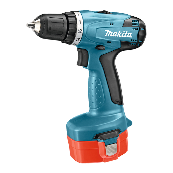
6281D
14.4V Cordless Driver Drill 10mm (3/8")
Battery
Battery
type
quantity
cover
No
---
No
1
1
1420
2
2
1422
2
2
PA14
2
2
Steel
Wood
Hard joint
Soft joint
Battery 1435
Charger DC1414
Battery 1435F
Charger DC1804
Battery PA14
Fast charger DC1439
Rechargeable
Plastic carrying
Charger
flashlight
No
No
No
DC1414
ML140
No
DC1414
ML140
No
DC1414
ML140
14.4
1.3/ 2.0/ 2.6
Ni-Cd/ Ni-Cd/ Ni-MH
180
0 - 1,300
0 - 400
0.8 - 10 (1/32 - 3/8)
10 (3/8)
25 (1)
16 stage + drill mode
1.0 - 4.0 (8.9 - 35.4)
30 (266)
36 (319)
20 (177)
Yes
Yes (2 speed)
Yes
Yes
1.6 (3.5)
Automotive charger DC1822
Drill bits for wood
Drill bits for steel
PRODUCT
L
W
Dimensions: mm (")
case
Length (L)
No
Width (W)
Height (H)
Yes
Yes
Yes
P 1/ 7
H
192 (7-9/16)
95 (3-3/4)
240 (9-1/2)
Driver bits
Advertisement

Related Manuals for Makita 6281D


Summary of Contents for Makita 6281D
- Page 1 Description 14.4V Cordless Driver Drill 10mm (3/8") ONCEPT AND MAIN APPLICATIONS Model 6281D has been developed as the successor model of 6280D, featuring: Single sleeve keyless drill chuck for easy bit installation/removal New tool design Model 6281D is available in the following variations.
-
Page 2: Necessary Repairing Tools
P 2/ 7 epair CAUTION: Remove the battery and the bit from the machine for safety before repair/ maintenance in accordance with the instruction manual! [1] NECESSARY REPAIRING TOOLS Description Use for Hex wrench 8 Removing / Installing Drill chuck Plastic hammer Removing Drill chuck [2] LUBRICATIONS The components of Gear ass’y has been lubricated in Makita plant and assembled under strict quality control. - Page 3 P 3/ 7 epair [3] DISASSEMBLY/ASSEMBLY [3]-2. Gear Ass’y, DC Motor DISASSEMBLING (1) Remove Keyless drill chuck. (2) Gear ass’y and DC Motor can be disassembled in the order of Figs. 3, 4, 5, 6 and 7. Fig. 3 Fig. 4 Gear ass’y Housing set (R) 3x16 Tapping...
- Page 4 P 4/ 7 epair [3] DISASSEMBLY/ASSEMBLY [3]-2. Gear Assembly, DC Motor ASSEMBLING The following portions of DC motor, Motor bracket and Gear ass’y have to face the same side. (Fig. 8) * Red point mark (designated as plus terminal) on DC Motor * None of protrusion side of Motor bracket * Gear assembly’s protrusion Fig.
- Page 5 P 5/ 7 epair [3] DISASSEMBLY/ASSEMBLY [3]-4. Leaf Spring ASSEMBLING Before assembling Gear ass’y and DC motor, Leaf spring has to be mounted to Housing set (L) as illustrated in Fig. 12. Fig. 12 Housing set (L) Leaf spring Leaf spring [3]-5.
-
Page 6: Circuit Diagram
P 6/ 7 ircuit diagram Fig. D-1 Connecting of Lead Wire (red) Color index of lead wires' sheath to DC Motor Black red point mark Connect Lead Wire (red) to the Terminal marked with red point mark. DC Motor Switch viewed from Switch viewed from Housing set (L) side Housing set (R) side... -
Page 7: Wiring Diagram
P 7/ 7 iring diagram Fig. D-2 Housing set (L) Rear view of Housing set (L) Red point mark DC Motor DC Motor has to be so assembled to Housing set (L) that its Red point mark Switchs’ Lead wires (black, red) have to be fixed with Lead wire is positioned on the back holder.