
Related Manuals for Philips KV-S5055C

Summary of Contents for Philips KV-S5055C
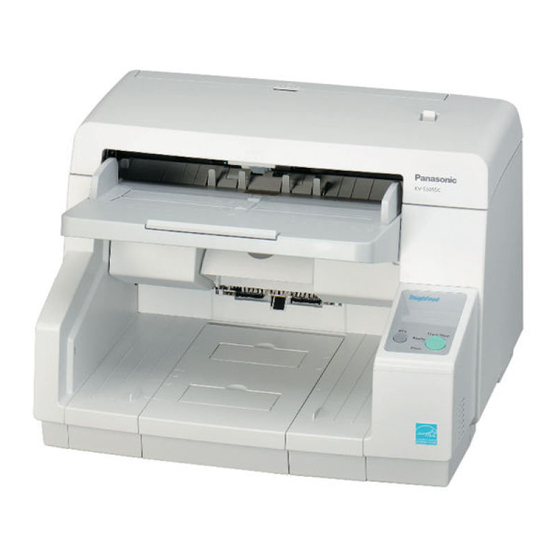
- Page 1 Order Number KM71005571CE Category Number G14 High Speed Color Scanner KV-S5055C Model No. © Panasonic System Networks Co., Ltd. 2010 Unauthorized copying and distribution is a violation of law.
-
Page 2: Table Of Contents
TABLE OF CONTENTS PAGE PAGE 1 GENERAL PRECAUTIONS -------------------------------------4 11.1. Block Diagram-1 (Image Processing) ------------- 122 1.1. Safety Precautions-----------------------------------------4 11.2. Block Diagram-2 (Board) ----------------------------- 123 1.2. Electrical Tests ----------------------------------------------4 11.3. Explanation of Connector----------------------------- 124 1.3. Standard for Repair Service -----------------------------4 12 SCHEMATIC DIAGRAM -------------------------------------- 132 1.4. - Page 3 15.17. DRIVE Board -------------------------------------------- 244 15.18. POWER Board ------------------------------------------ 247...
-
Page 4: General Precautions
1 GENERAL PRECAUTIONS 1.1. Safety Precautions 1. Before servicing, unplug the power cord to prevent electrical shock hazard. 2. When replacing parts, use only manufacture’s recommended components for safety. 3. Check the condition of power cord. Replace if wear or damage is evident. 4. -
Page 5: For Service Technicians
1.4. For Service Technicians ICs and LSIs are vulnerable to static electricity. When repairing, the following precautions will help to prevent recurring malfunctions. 1. Cover plastic parts with aluminum foil. 2. Ground soldering irons. 3. Use a conductive mat on the worktable. 4. -
Page 6: Specifications
2 SPECIFICATIONS Item Model No. KV-S5055C Series Scanner Scanning Face Duplex Scanning Method CCD and LED for Front side CCD and LED for Back side Scanning Width 305 mm (12.0 in.) Black & White: 50 ppm / 100 ipm (A4, 300 dpi, Portrait) Readout Speed Black &... - Page 7 Note: : KV-S5055C Series Model Area Serial No. Power Cord KV-S5055C D36 xxxx 1001 For 100 to 120 V KV-S5055C-J USA (made in Japan) D56 xxxx 1001 For 100 to 120 V KV-S5055C-U Europe, Russia D50 xxxx 1001 For 220 to 240 V...
-
Page 8: Component Identification
3 COMPONENT IDENTIFICATION Main Part Names and Locations 3.1. -
Page 10: Control Panel
3.2. Control Panel Fig.3.2.1 Function of Control Panel keys and indications Name Operation Remarks DFS (Double- When a double-feed occurs, push this key to continue scanning the double-feed detected feed Skip) key sheet and the following sheet on the Hopper. Start/Stop key (1) Push this key to start scanning if you set [Wait Key] to "Manual Feed Mode"... -
Page 11: Installation
4 INSTALLATION 4.1. Minimum Space Requirements Be sure to maintain the recommended space requirements for proper ventilation. Fig.4.1.1 Dimensions for proper ventilation Top View Left-side View... -
Page 12: Included Accessories
4.2. Included Accessories Confirm that the following items are included with the scanner. -
Page 13: Installing Double-Feed Prevention Roller
4.3. Installing Double-feed Prevention Roller 1. Remove all packing tape. 2. Push the ADF Door Release (1) to open the ADF door (2). 3. Pull towards you and remove the Double-feed Prevention Roller Cover by using the indent (1). 4. Install the Double-feed Prevention Roller. •... - Page 14 5. Insert the protrusion (1) of the Double-feed Prevention Roller Cover into the holes on the main unit, and then push in the part of the roller cover indicated by (2) in the direction indicated by the arrows until it clicks into place. Note Make sure that the Double-feed Prevention Roller Cover does not stick up.
-
Page 15: When Scanning Documents Of Different Sizes Together
4.4. When Scanning Documents of Different Sizes Together Note See the following conditions for scanning documents of different sizes together. • Document thickness The ratio of the thickness between the thickest paper and thinnest paper must be less than 1.5. •... - Page 16 3. Spread the Document Guides as far apart as they will go. 4. Align the documents along one side of the guides. 5. Slide the Document Guides to align the document position so that the center of the smallest sheet can be fed into the center of the paper slot.
-
Page 17: Dimm Module Extension
Note 1: If configurations requiring a lot of memory (high resolution, color mode, etc.) are used with KV-S5055C Series, the scanning will be suspended intermittently while the data is being transferred to the computer. As a result, the images may be disrupted slightly due to the effect of suspending the scanning. - Page 18 Fig.4.5.1: Additional memory size -1 (Unit: MB) : 305 mm x 2,540 mm (12.0 x 100 in.) Mode Size Binary SC's Max Double Letter Legal Letter 8 bit Gray SC's Max Double Letter Legal Letter 24 bit Color SC's Max Double Letter Legal Letter...
-
Page 19: Installing Dimm Modules
Fig.4.5.2: Additional memory size -2 (Unit: MB) 305 mm x 2,540 mm (12.0 x 100 in.) Mode Size Binary + 8 bit SC's Max Gray Double Letter Legal Letter Binary + SC's Max 24 bit Color Double Letter Legal Letter 4.6. -
Page 20: Connecting The Scanner To A Personal Computer
4.7. Connecting the Scanner to a Personal Computer Connect the accessories’ Power Cord and USB cable to the back of the unit. Caution: 1. Only use the Power Cord and USB Cable enclosed in this scanner. 2. Be sure to connect the scanner directly to the USB interface port on the PC. We cannot guarantee that the scanner will work properly if it is connected to a USB hub. -
Page 21: System Requirements
4.8. System Requirements When using the scanner, the minimum system requirements are as follows. Computer IBM PC/AT or compatible machine with a CD-ROM drive ® Intel Core™ 2 Duo, 1.8 GHz or higher Operating System ® ® ® Windows XP (64 bit Edition is not supported.), Windows Vista , or Windows Interface USB 2.0... -
Page 22: Sectional View
5 SECTIONAL VIEW 5.1. Bottom Block... -
Page 23: Back Block
5.2. Back Block... -
Page 24: Upper Block
5.3. Upper Block... -
Page 25: Lower Block
5.4. Lower Block 5.4.1. Mechanical Parts... - Page 26 5.4.2. Boards...
-
Page 27: Mechanical Function
6 MECHANICAL FUNCTION 6.1. Paper Feed Mechanism (Auto) (Fig. 6.1.1) 1. When the documents are set on the Hopper and the scanning command is issued from PC, the Conveyor Motor will be driven to rotate the three Drive Rollers (Drive Roller 1 to 3) and Exit Roller. And at this time, the gate will open. 2. - Page 28 4. Then, the leading edge of the document advances to the Drive Roller 1 position, and then passes through the Slip Detect Sensor. At this time, if the document does not advance within a defined period, the pressure applied to the Separation Roller from the Double-feed Prevention Roller is strengthened to prevent the document from slipping.
-
Page 29: Paper Feed Mechanism (Manual)
6.2. Paper Feed Mechanism (Manual) When scanning multipart paper with the Manual Feed Selector set to “AUTO”, the Double-feed Prevention Roller is pressed against the Separation Roller, and this results in a separating force being applied to the document, which will separate the layers, resulting in damage to the document. -
Page 30: Paper Feed Operation
6.3. Paper Feed Operation 1. When the Paper Feed Motor rotates the Paper Feed Motor in the paper feed direction, Paper Feed Roller will go down until the roller is in contact with, and then rotate in the paper feed direction. (Arrows 1 →2 → 3 → 4) At this time, Separation Roller will also rotate in the paper feed direction. - Page 31 2. On the other hand, when the Paper Feed Motor rotates the Paper Feed Motor in the reverse direction of paper feed, the Paper Feed Roller will rise and won't rotate. (Arrows 1→ 2→ 3) At this time, Separation Roller will also rotate in the paper feed direction. (Arrows 1→ 2→ 3)
-
Page 32: Glass Cleaning Mechanism (Auto)
6.4. Glass Cleaning Mechanism (Auto) After turning on the scanner or finishing scanning, this scanner will rotate the Conveyor Motor in the reverse direction of paper-feed to rotate the Reference Plates (F) and (B). This performance will enable the brush attached on the plates clean the glass surfaces. 6.5. -
Page 33: Maintenance
7 MAINTENANCE 7.1. Maintenance Chart C: Clean R:Replace (x 1000 sheets) Description Part Reference 80 - 320 340 350 Section Paper Feed Roller Sec. 14.4 Clean each part every 20,000 sheets' scanning. Separation Roller Sec. 14.4 Double-feed Prevention Roller Sec. 14.2 Drive Roller 1 Sec. -
Page 34: Cleaning
7.2. Cleaning 7.2.1. Preparation 1. Before cleaning, make sure to turn off the scanner. 2. Push the ADF Door Release to open the door. - Page 35 7.2.2. Cleaning-1 (Main) Following the instructions in figures Fig.7.2.2-1, Fig.7.2.2-2, Fig.7.2.2-3, and Fig.7.2.2-4 below, wipe or blow off dust from the surface of the following parts in order to maintain high scanning performance. Note: After cleaning the Paper Feed Roller, Separation Roller, and Double-feed Prevention Roller, execute “Clear Counter for cleaning roller”...
- Page 36 Note 3: In case that a scanning problem on the image quality (line) or on the performance of conveying still occurs, with a vacuum cleaner, remove any staples and paper dust inside and outside the scanning glass, being careful not to scratch the glass surface or its surroundings. (Don't clean the glass surface or its surroundings with the included Blower.) Note 4: Direction for wiping rollers...
- Page 37 (Fig. 7.2.2-2) Cleaning Position 1 (Rollers)
- Page 38 (Fig. 7.2.2-3) Cleaning Position 2 (Sensors, Glass, Plates) Note: * How to blow off any dirt that has accumulated on the self-cleaning brushes attached to the Reference Plates (F) and (B) 1. Rotate the Reference Plates (F) and (B) in the direction of the arrows so that you can see the brush.
- Page 39 (Fig. 7.2.2-4) Cleaning Position 3 (Reflector Sheets)
- Page 40 7.2.3. Cleaning-2 (Others: Exit Roller, Exit Sensor) 1. Remove the Exit Roller. (See 8.5.32.) 2. With the included Roller Cleaning Paper or Model KV-SS03 (Option: Roller Cleaning Paper), clean the surface of the Exit Roller. When cleaning it, wipe off the dust on the roller surface all the way around it, proceeding from one end to the other in the direction of the arrows shown in the figure.
-
Page 41: Replacing Limited Life Parts
7.3. Replacing Limited Life Parts 7.3.1. Replacing Paper Feed Roller Module (1) Turn off the scanner. (2) Remove the current Paper Feed Module. (See 8.4.1.) (3) Take out a new Paper Feed Module in the optional "Roller Exchange Kit (KV-SS039)". (4) Install the new Paper Feed Module. - Page 42 7.3.2. Replacing Double-feed Prevention Roller (1) Turn off the scanner. (2) Remove the current Double-feed Prevention Roller. (See 8.5.12.) (3) Take out a new Double-feed Prevention Roller in the optional "Roller Exchange Kit (KV-SS039)". (4) Install the new Double-feed Prevention Roller. Align the shaped shaft with the notch in the roller mount, and then insert the shaft in the notch.
-
Page 43: Disassembly Instructions
8 DISASSEMBLY INSTRUCTIONS 8.1. Disassembly Flowchart The flowchart indicates disassembly sequence for the Exterior, Mechanical parts, Unit Components, and Circuit Board assemblies. When reassembling, perform the steps in the reverse order unless otherwise instructed in Reassembling Notes. Note: Disassembly flowchart explanation * This sample flowchart shows that, to disassemble C, the procedures 1 and 2 must be performed first before proceeding to the procedure 3. -
Page 46: Bottom Block
8.2. Bottom Block 8.2.1. CONTROL Board and DRIVE Board 1. Remove the 8 screws (a) and 2 screws (b) that support the Cover Plate on the bottom of the scanner. Then, remove the Cover Plate. 2. Disconnect all connectors (9 connectors and 2 flat cables) on the CONTROL Board. -
Page 47: Back Block
8.3. Back Block 8.3.1. Imprinter Door 1. Open the Imprinter Door. 2. While pushing the ribs of the door in the direction of the arrow (1), pull the door away in the direction of the arrow (2) to remove it. 8.3.2. - Page 48 8.3.3. USS RELAY Board 1. Remove the Rear Cover. (See 8.3.2.) 2. Disconnect the 3 connectors. Then, release them from the clampers. 3. Disconnect the flat cable. 4. Remove the 3 screws. Then, remove the USS RELAY Board. 8.3.4. Optical Unit Front 1.
- Page 49 5. Remove the 2 screws on both sides of Optical Unit Front. 6. While holding up the Optical Unit Front, pull the unit horizontally and backwards to remove it. 8.3.5. Sub Exit Conveyor Assembly 1. Remove the Optical Unit. (See 8.3.4.) 2.
-
Page 50: Upper Block
8.4. Upper Block 8.4.1. Paper Feed Module 1. Push the ADF Door Release to open the ADF Door. 2. Move the lever (A) of the Paper Feed Roller Module in the order indicated by the arrows ((1), (2)), and then pull out the module towards you. - Page 51 8.4.4. Sub Conveyor Plate 1. Push the ADF Door Release to open the ADF Door. 2. Remove the 2 screws. 3. Remove the 2 screws (1 from each side). 4. Remove the Sub Conveyor Plate from the scanner. Reassembling Note: When reassembling the Sub Conveyor Plate, be sure to insert the plate inside the claws of the Sub Chassis R and Sub Chassis L.
- Page 52 4. Remove the 2 screws on the STARTING SENSOR Board. 5. After releasing the connector to the STARTING SENSOR Board from the clamper, disconnect the connector.
- Page 53 8.4.6. Reference Plate (B) 1. Remove the Light Unit (F). (See 8.4.3.) 2. Remove the 2 springs (1 from each side of the Reference Plate (B)). Disassembling Note: How to remove springs Make sure to release one side of the spring hook while holding the other side of the spring hook not to lose the spring.
- Page 54 3. Release the 2 poly-sliders that hold the Reference Plate (B) on both sides. 4. Remove the Gear and poly-slider. 5. Slide and remove the plate. Reassembling Note: How to attach the spring 1. With one side of the spring hung to a wire (about 3 inches long), reassemble the spring around the Reference Plate (B).
-
Page 55: Top Cover
8.4.7. Inner Cover T 1. Push the ADF Door Release to open the ADF Door. 2. Remove the screw. 3. Pull out and remove the Inner Cover T. 8.4.8. Top Cover 1. Remove the Inner Cover T. (See 8.4.7.) 2. Remove the 2 screws. 3. - Page 56 8.4.9. BENT RELAY Board 1. Remove the Imprinter Door. (See 8.3.1.) 2. Remove the Top Cover. (See 8.4.8.) 3. Release the 2 connectors from the clampers. 4. Disconnect the 5 connectors to the BENT RELAY Board. 5. Remove the 2 screws on the BENT RELAY Board. 8.4.10.
- Page 57 5. Remove the screw, and then disconnect the connector from the BENT RELAY Board. 6. Pull out the BENT PAPER S (R) Board and BENT PAPER R (R) Board. 7. Disconnect the connector to the BENT PAPER S (R) Board. 8.
- Page 58 8.4.12. BENT PAPER S (L) Board and BENT PAPER R (L) Board 1. Remove the Imprinter Door. (See 8.3.1.) 2. Remove the Top Cover. (See 8.4.8.) 3. Remove the spring to release the Lock Assembly from the scanner. 4. Remove the Lock Assembly. 5.
- Page 59 8.4.13. Paper Feed Motor 1. Remove the Imprinter Door. (See 8.3.1.) 2. Remove the Top Cover. (See 8.4.8.) 3. Remove the screw (a) and 2 screws (b) that fasten the Motor Bracket in place. 4. After releasing the connector wires from the clampers, disconnect the connector to the Paper Feed Motor that is being held by the bracket.
- Page 60 4. Disconnect the connector and remove the screw. 8.4.15. SLIP DETECT SENSOR Board 1. Remove the Paper Feed Motor. (See 8.4.13.) 2. Remove the PAPER FEED SELECT SENSOR Board. (See 8.4.14.) 3. Remove the screw (a) and 3 screws (b) that fasten the Reinforcement Plate 2 to the scanner.
- Page 61 5. Disconnect the connector to the SLIP DETECT SENSOR Board. 6. Remove the screw on the SLIP DETECT SENSOR Board.
-
Page 62: Lower Block
8.5. Lower Block 8.5.1. Right Cover (with Right Front Cover) 1. Remove the 2 screws on the right side of the scanner. 2. Push the ADF Door Release to open the ADF Door 3. Remove the screw (a) and screw (b). 4. - Page 63 5. Disconnect the connector from the PANEL Board to release the Right Cover (with Right Front Cover) from the scanner.
- Page 64 8.5.2. Right Front Cover 1. Remove the Right Cover with Right Front Cover. (See 8.5.1.) 2. Remove the 3 screws to release the Right Front Cover from the Right Cover. 8.5.3. PANEL Board 1. Remove the Right Front Cover. (See 8.5.2.) 2.
- Page 65 8.5.4. 1. Remove the Right Cover (with Right Front Cover). (See 8.5.1.) 2. Remove the 2 screws. 3. Disconnect the connector from the POWER Board. 8.5.5. Micro Switch 1. Remove the Right Cover (with Right Front Cover). (See 8.5.1.) 2. Disconnect the connector. 3.
- Page 66 8.5.6. Power Box 1. Remove the 2 screws from the front right of the scanner. 2. Remove the screw (a) and 2 screws (b) from the back right of the scanner. Then pull off the Power Box. 3. Disconnect the 2 connectors to release the Power Box from the scanner.
- Page 67 8.5.7. POWER Board 1. Remove the Power Box. (See 8.5.6.) 2. Remove the 5 screws that fasten the Power Box Cover to the Power Box. 3. Remove the 7 screws on the POWER Board. 4. Remove the 3 screws that fasten the Heatsink to the side of the Power Box.
- Page 68 4. While releasing the holder’s 3 claws, pull out the Ionizer Board.
- Page 69 8.5.9. Left Cover 1. Remove the 2 screws on the left of the scanner. 2. Push the ADF Door Release to open the ADF Door. 3. Remove the screw. 4. While releasing the 3 claws, pull the Left Cover forward.
- Page 70 8.5.10. USR RELAY Board 1. Remove the Left Cover. (See 8.5.9.) 2. Disconnect the 5 connectors. 3. Remove the 2 screws on the USR RELAY Board. 8.5.11. Drive Belt 1. Remove the Left Cover. (See 8.5.9.) 2. Loosen the 2 screws. Push down the lever until the belt goes slack, and then tighten the screws to hold the lever in place.
- Page 71 8.5.12. Double-feed Prevention Roller 1. Push the ADF Door Release to open the ADF Door. 2. Open and remove the Double-feed Prevention Cover. 3. While releasing the claw, remove the Double-feed Prevention Roller.
- Page 72 8.5.13. Hopper Plate Assembly 1. Remove the Double-feed Prevention Roller. (See 8.5.12.) 2. Remove the screw. 3. While releasing the 3 claws on the bottom of Hopper Plate Assembly and pushing down the top of the Gate, pull and remove the assembly forward. (1) While pull the Hopper Plate Assembly forward, release the 3 claws (Claw1).
-
Page 73: Paper Sensor
8.5.14. Paper Sensor 1. Remove the Hopper Plate Assembly. (See 8.5.13.) 2. Remove the screw to release the Paper Sensor with plate from the Hopper Plate Assembly. 3. Remove the screw to separate the sensor from the plate. 8.5.15. USR SENSOR Board 1. - Page 74 8.5.16. DFP Pressure Motor 1. Remove the Left Cover. (See 8.5.9.) 2. Remove the Hopper Plate Assembly. (See 8.5.13.) 3. Remove the screw (a) and 4 screws (b) on the Reinforcement Plate. 4. Remove the screw (a) on the left side. 5.
- Page 75 7. Disconnect the connector, and then remove the 2 screws to release the motor from the plate. 8.5.17. DFP HOME SENSOR Board 1. Remove the DFP Pressure Motor. (See 8.5.16.) 2. Remove the screw, and then disconnect the connector of the DFP HOME SENSOR Board.
- Page 76 8.5.19. Discharge Brush 1. Remove the Inner Cover C. (See 8.5.18.) 2. Remove the 2 screws that fasten the Discharge Brush. 8.5.20. Conveyor Motor 1. Remove the Drive Belt. (See 8.5.11.) 2. Remove the Inner Cover C. (See 8.5.18.) 3. Remove the Inner Cover L. 4.
- Page 77 6. Disconnect the connector. 7. Remove the Heatsink from the Conveyor Motor. 8. Pull and remove the Conveyor Motor.
- Page 78 8.5.21. Optical Unit Back 1. Remove the Conveyor Motor. (See 8.5.20.) 2. Remove the 2 screws that fasten the Optical Unit Back to the scanner. 3. Pull the unit horizontally and forward to remove it. 4. Disconnect the 2 connectors to release the unit from the scanner.
- Page 79 8.5.22. ENDING SENSOR Board 1. Remove the Optical Unit Back. (See 8.5.21.) 2. Remove the screw, and then disconnect the connector. 8.5.23. Scanning Glass (B) 1. Remove the Left Cover. (See 8.5.9.) 2. Remove the Right Cover. (See 8.5.1.) 3. Remove the Rear Cover. (See 8.3.2.) 4.
- Page 80 8.5.24. Light Unit (B) 1. Remove the Scanning Glass (B). (See 8.5.23.) 2. Remove the screw on the right, as seen from the back. 3. Remove the screw and disconnect the connector on the left, as seen from the back. 4.
- Page 81 8.5.25. Reference Plate (F) 1. Remove the Light Unit (B). (See 8.5.24.) 2. Remove the 2 springs (1 from each side of the Reference Plate (F)). Disassembling Note: How to remove springs Refer to 8.4.6. 3. Release the 2 poly-sliders on both sides that fasten the Reference Plate (F) to the scanner.
- Page 82 8.5.26. Conveyor 1 1. Remove the Left Cover. (See 8.5.9.) 2. Remove the Right Cover. (See 8.5.1.) 3. Remove the Rear Cover. (See 8.3.2.) 4. Remove the screw with a washer on the right, as seen from the back. 5. Remove the screw on the left, as seen from the back. 6.
- Page 83 8.5.28. Ionizer L and Ionizer R 1. Remove the Drive Roller 2. (See 8.5.27.) 2. Remove the 2 screws (1 from each Ionizer). 3. Remove the 2 screws with ground-lugs (1 from each Ionizer). 4. Pull the Ionizer L and Ionizer R. 8.5.29.
- Page 84 8.5.30. Conveyor 2 1. Remove the Left Cover. (See 8.5.9.) 2. Remove the Right Cover. (See 8.5.1.) 3. Remove the Rear Cover. (See 8.3.2.) 4. Remove the screw with a washer on the right, as seen from the back. 5. Remove the screw on the left, as seen from the back. 6.
- Page 85 8.5.32. Exit Roller 1. Remove the Conveyor 2. (See 8.5.30.) 2. Remove the Power Box. (See 8.5.6.) 3. Remove the Drive Belt. (See 8.5.11.) 4. Remove the Discharge Brush. (See 8.5.19.) 5. Pull out the Exit Roller in the direction of the arrow.
-
Page 86: Service Utility & Self Test
9 SERVICE UTILITY & SELF TEST 9.1. Main Menu Indication for Service Utility This section describes the functions of the service utility software, such as adjustments, diagnosis, configuration and maintenance. This utility software also includes the functions contained in the User Utility software enclosed in the scanner. Executing “ServiceUtility.exe”... -
Page 87: List Of Functions For Service Utility
9.2. List of Functions for Service Utility Service Utility item list is as follows. Note: When two or more scanners are connected to a PC, execute “Select Scanner” to specify the scanner before evaluating. The procedure is as follows. 1. Click “Select Scanner” on the main menu. 2. - Page 88 Item Purpose Remarks Adjust Shading Used to execute shading correction All Position Used to adjust scanning length, paper end position, width, vertical position, and horizontal position adjustment for front and back sides automatically Individual Position 1. Used to execute automatic length, paper end position, width, vertical position, or horizontal position adjustment for front and back sides, individually 2.
-
Page 89: Code 00 00 00
9.3. Operation This section describes each operation (or status indication), according to the function item list shown in Sec.9.2. 9.3.1. Scanner Status This function indicates the scanner status, and updates it every few seconds. The status messages and their contents are as follows. - Page 90 9.3.2. Error Code Classification and Error codes are as follows. And troubleshooting for this error message and codes is shown in Sec.10.2. Fig. 9.3.2.1 Classification Code Outline Classifica- Contents Classifica- Contents Classifica- Contents tion Code tion Code tion Code Document —...
- Page 91 Fig.9.3.2.3 Error Code Classifica- Error Code Contents tion Code No error Stop by clicking “STOP” Stop by ADF stop-command Paper feed jam (Paper didn’t reach the Waiting Sensor.) Conveyor jam 1 (Paper didn’t reach the Slip Detect Sensor.) Conveyor jam 2 (Paper didn’t reach the Starting Sensor.) Conveyor jam 3 (Paper didn’t reach the Exit Sensor.) Exit jam (Paper did not pass through the Exit Sensor.) Document remains in scanner (...
- Page 93 9.3.3. Scanner Information This function provides various types of scanner information to the user or service-person. Main contents are as follows. 1. Model 2. Firmware Version 3. Board and Gate Array (LSI) versions 4. Memory size for front and back sides 5.
- Page 94 9.3.5. Scanner Condition Item Operation Default Remarks Sleep Mode 1. Click “Sleep Mode” on the main menu (Service Utility). 15 minutes When returning back to the 2. Set “Waiting Time” (Unit: minutes) to specify the amount of Ready Mode from the Sleep time until the scanner enters the sleep mode.
- Page 95 9.3.6. Test Item Operation Default Remarks 1. Click “LED” on the main menu. — Each indicator turns on or off 2. Click “START” on “LED” dialog box to start LED Test in a constant period. continuously until clicking “STOP”. 3. Click “Close” to return to the main menu. Key / Sensor 1.
- Page 96 Item Operation Default Remarks Feed 1. Set documents on the Hopper. — 2. Click “Feed” on the main menu. 3. Set “Test Mode” and “Test Condition” depending on each scanning condition. Note: Operation “Imprinter” is available only when the optional Imprinter is installed. 4.
- Page 97 Item Operation Default Remarks Image Sensor 1. Click “Image Sensor Output” on the main menu. — Note: This operation indicates a Output 2. Push the ADF Door Release to open the ADF Door. And sensor output waveform hold a sheet of clean white paper between the Scanning to check whether there is Glass (F) and Scanning Glass (B), and then close the ADF any partial depression of...
- Page 98 9.3.7. Adjustment Item Operation Default Remarks Shading 1. Click “Shading” on the main menu. — Until this process is 2. Confirm the message “The data of User Shading will be completed, don’t stop the also overwritten” on the display. process by opening any And if the message is acceptable, click “OK”.
- Page 99 Item Operation Default Remarks Individual Position 1. Adjust Automatically. — 1. “Adjust Automatically” a. Set test chart A (Part No.: See 14.8.) on the Hopper. a. Length b. Click “Individual Position” on the main menu. b. Paper End Position c. Click one of 8 “Adjust Automatically” buttons on the c.
- Page 100 Item Operation Default Remarks Double Feed 1. Adjust Automatically. — a. Set the Shading Sheet (Part No.: See 14.8.) on the Hopper in portrait orientation, sliding the Document Guides so that they match the document width. b. Click “Double Feed” in “Adjust” section on the main menu.
- Page 101 Item Operation Default Remarks Bent Paper 1. Click “Bent Paper Sensor” on the main menu. — Sensor 2. Lay the Shading Sheet (See 14.8.) on the ADF Door, which covers all Bent Paper Sensors on the BENT PAPER S (L) SENSOR Board, BENT PAPER S (R) SENSOR Board, BENT PAPER R (L) SENSOR Board, and BENT PAPER R (R) SENSOR Board as shown in Sec.5.
- Page 102 Item Operation Default Remarks Feed Speed 1. Click "Feed Speed" on the main menu. 100 % 2. Change the parameter (%: 10 to 100). 3. Click "OK" to renew the setting, and to return to the main menu. Note: 1. Reducing the Feed Speed to slow may reduce the number of paper-jams or double-feeds.
-
Page 103: Scanner Self-Test
9.4. Scanner Self-test Without connecting the scanner to the PC, the following scanner self-test can be performed. The following mechanical test is generally used after replacing or reassembling rollers (Drive Rollers) and other mechanical parts related to feeding documents. Test Item Operation LED or Indicator Status Remarks... - Page 104 5. Feed 1 While pushing the “START/STOP Key” on the Control — — Panel, turn on the scanner. 2 Release the key after LED (Back) status changes to OFF → blinking. Blinking Blinking → 3 Push the “START/STOP Key” once to enter the test Count selection mode.
- Page 105 1 While pushing the “START/STOP Key” on the Control — — *9: Every time you Lamp Test push the Panel, turn on the scanner. “START/STOP” 2 Release the key after LED (Back) status changes to OFF → Key, the lamp blinking.
-
Page 106: Troubleshooting
10 TROUBLESHOOTING 10.1. Troubleshooting-1 (with no error message on PC) Symptom Possible Cause Check Point Remarks No power 1. Power cord is not inserted correctly Insert the power cord correctly. 2. Cables in the scanner are not connected Insert the cables properly. Pay attention properly. -
Page 107: U11
10.2. Troubleshooting-2 (with an error message on PC) Error Code Possible Cause Check Point Remarks Classified Code ST1 ST2 ST3 ST4 U11(Paper feed jam): 00 1. Paper Feed Roller module or 1. Reassemble the rollers. Paper did not reach the DFP Roller is not assembled 2. -
Page 108: U12
Error Code Possible Cause Check Point Remarks Classified Code ST1 ST2 ST3 ST4 7. Paper Feed Motor control circuit 1. Check the following connection and does not work, properly. soldering condition on each connector. → CN1002 (CONTROL Board) to CN4002 (DRIVE Board) 2. -
Page 109: U13
Error Code Possible Cause Check Point Remarks Classified Code ST1 ST2 ST3 ST4 5. Conveyor Motor does not work 1. Check the motor mechanism condition by properly. carrying out Conveyor Motor test. (See 9.3.6.) 2. Check the following connection and soldering condition on each connector. -
Page 110: U14
Error Code Possible Cause Check Point Remarks Classified Code ST1 ST2 ST3 ST4 3. Starting Sensor does not work, 1. Execute Key/Sensor test in the Sec. 9.3.6 to correctly. check the sensor condition. 2. Check the sensor alignment is proper. (whether the sensor direction faces to its reflector) 3. -
Page 111: U16
Error Code Possible Cause Check Point Remarks Classified Code ST1 ST2 ST3 ST4 3. Exit Sensor does not work, 1. Execute Key/Sensor test in the Sec. 9.3.6 to correctly check the sensor condition. 2. Check the sensor alignment is proper (whether the sensor direction faces to its reflector.) 3. - Page 112 Error Code Possible Cause Check Point Remarks Classified Code ST1 ST2 ST3 ST4 U23 (Double-feed 00 1. Document quality is out of spec. 1. Set the correct documents on the Hopper error) on this scanner. according to this scanner specification. Note: Refer to Sec.2.
-
Page 113: U30
Error Code Possible Cause Check Point Remarks Classified Code ST1 ST2 ST3 ST4 6. Double Feed Detector (R) does 1. Execute Double Feed test in Sec.9.3.6 to not work, properly. check the detector condition. 2. Check whether the Double Feed Detector (R) is aligned property. -
Page 114: F17
Error Code Possible Cause Check Point Remarks Classified Code ST1 ST2 ST3 ST4 2. Door Switch (Micro switch) does 1. Execute Key/Sensor in Sec. 9.3.6 to check not work correctly. the door switch (Door Sensor) ON/OFF condition. 2. Check the condition between the Door Switch and CN4006 on DRIVE Board. -
Page 115: F35
Error Code Possible Cause Check Point Remarks Classified Code ST1 ST2 ST3 ST4 F35 (Image process- 00 Access error to DDR2(IC0033 or 1. Check the soldering condition of the parts ing FPGA/DDR2 error) IC0034) surrounding FPGA (IC0030 and IC0031). 2. Check the soldering condition of the DDR2 (IC0033 and IC0034). -
Page 116: F61
Error Code Possible Cause Check Point Remarks Classified Code ST1 ST2 ST3 ST4 3. Pixel data from Optical Unit 1. Check the following connections and Front or image processing soldering condition on each connector. circuit has some problems. a. CN5002 (CCD (F) Board) to CN1003 (CONTROL Board) b. -
Page 117: F63
Error Code Possible Cause Check Point Remarks Classified Code ST1 ST2 ST3 ST4 F63 (Back-side 00 1. Pixel data from Optical Unit Back Refer to the above 3rd item on the F62. black level error) or image processing circuit has some problems. F80 (Double Feed 00 1. -
Page 121: Requirement After Parts Replacement
10.3. Requirement After Parts Replacement Required adjustment Remarks Replaced circuit board assembly or part IC0007 (Flash memory on CONTROL Board) or 1. Adjust Shading. CONTROL Board IC0004 (EEPROM on CONTROL Board) or CONTROL 1. Adjust Shading. Board 2. Adjust Individual position manually, as required. 3. -
Page 122: Circuit Description
11 CIRCUIT DESCRIPTION 11.1. Block Diagram-1 (Image Processing) On this system, the CPU (IC0006) controls the operation of the USB Controller (IC0010), the Gate Arrays (ASICs: IC0035 and IC0038), the Sensors (Paper Sensor and others), and the Motors (Paper Feed, Conveyor, DFP Pressure). Motor pulse signals for conveying paper (Conveyor Motor) are provided from the Gate Array (ASIC: IC0035). -
Page 123: Block Diagram-2 (Board)
11.2. Block Diagram-2 (Board) CN3015 CN3013 CN2014 CN3004 CN2008 CN2009 CN3014 CN3011 CN2013 CN3009 CN2011 CN1015 CN1014 DDR2 CN1016 87831 DDR2 CN1002 CN1001 CN4002 CN4001 CN4002 CN4001 Door Switch... -
Page 124: Explanation Of Connector
11.3. Explanation of Connector CN1003 (CONTROL Board) - CN5002 (CCD (F) Board) Pin No. Signal Name Description CN1003 CN5002 RCLK_F LVDS RCLK+ *RCLK_F LVDS RCLK- RB_F LVDS RB+ *RB_F LVDS RB- RA_F LVDS RA+ *RA_F LVDS RA- RE_F LVDS RE+ *RE_F LVDS RE- RD_F... - Page 125 CN1006 (CONTROL Board) - CN5003 (CCD (B) Board) Pin No. Signal Name Description CN1006 CN5003 12V supply Ground 5V supply Ground 3.3V 3.3V supply Ground AFE_CLK AFE serial clock AFE_SDI AFE serial data out AFE_SENB AFE serial enable LSYNC_B Line sync *SRES Reset AFE_SDOB...
- Page 126 CN1001 (CONTROL Board) - CN4001 (DRIVE Board) Pin No. Signal Name Description CN1001 CN4001 24VIL +24V +14V Ground Ground Ground 3.3VCPU +3.3V for CPU ROM SRAM USBC 3.3VSLP +3.3V for ASIC DRAM 3.3VSLP +3.3V for ASIC DRAM Ground Ground CN1002 (CONTROL Board) - CN4002 (DRIVE Board) Pin No.
- Page 127 CN1009 (CONTROL Board) - CN3001 (PANEL Board) Pin No. Signal Name Description CN1009 CN3001 LED_GREEN Green LED *KEY_SS Start/Stop Key *KEY_CONTINUE Continue Key BUZZER buzzer Ground Ground +12V N.C. N.C. LED_RED Red LED LED_RED Red LED CN1010 (CONTROL Board) - Imprinter Pin No.
- Page 128 CN4004 (DRIVE Board) - Paper Feed Motor Pin No. Signal Name Description CN4004 Paper Feed Motor — *FEED_RB Paper Feed Motor phase (B-) — COMMON_RB +24V (Interlock switch and Fuse) — FEED_RB Paper Feed Motor phase (B+) — FEED_RA Paper Feed Motor phase (A+) —...
- Page 129 CN841 (POWER Board) - CN4003 (DRIVE Board) Pin No. Signal Name Description CN841 CN4003 Over voltage protect 3.3CPU 3.3CPU Ground Ground Ground *SLEEP_PWR Power Board Low mode *OVP Over voltage protect CN842 (POWER Board) - Fan Pin No. Signal Name Description CN842 —...
- Page 130 CN2005 (USR RELAY Board) - CN2010 (USR SENSOR Board) Pin No. Signal Name Description CN2005 CN2010 USR+ Ultra sonic receive+ N.C. N.C. N.C. N.C. USR- Ultra sonic receive- CN2007 (USS RELAY Board) - CN3005 (BENT RELAY Board) Pin No. Signal Name Description CN2007 CN3005...
- Page 131 CN3008 (BENT RELAY Board) - CN2013 (SLIP DETECT SENSOR Board) Pin No. Signal Name Description CN3008 CN2013 IMP_START Slip Detect Sensor Signal 5VSLP 5 V supply Ground Ground CN3006 (BENT RELAY Board) - CN3010 (BENT PAPER SENSOR R (L) Board) Pin No.
-
Page 132: Schematic Diagram
12 SCHEMATIC DIAGRAM Index 12.1 CONTROL Board 12.2 PANEL and SENSOR Boards PANEL Board DFP HOME SENSOR Board ENDING SENSOR Board PAPER FEED SELECT SENSOR Board BENT RELAY Board BENT PAPER SENSOR R(L) Board BENT PAPER SENSOR R(R) Board BENT PAPER SENSOR S(L) Board BENT PAPER SENSOR S(R) Board 12.3 RELAY and SENSOR Boards USS RELAY Board... -
Page 133: Control Board
12.1. CONTROL Board... -
Page 159: Panel And Sensor Boards
12.2. PANEL and SENSOR Boards 12.2.1. PANEL Board... - Page 160 12.2.2. DFP HOME SENSOR Board...
- Page 161 12.2.3. ENDING SENSOR Board...
- Page 162 12.2.4. PAPER FEED SELECT SENSOR Board...
- Page 163 12.2.5. BENT RELAY Board...
- Page 164 12.2.6. BENT PAPER SENSOR R (L) Board...
- Page 165 12.2.7. BENT PAPER SENSOR R (R) Board...
- Page 166 12.2.8. BENT PAPER SENSOR S (L) Board...
- Page 167 12.2.9. BENT PAPER SENSOR S (R) Board...
-
Page 168: Relay And Sensor Boards
12.3. RELAY and SENSOR Boards 12.3.1. USS RELAY Board... - Page 170 12.3.2. USR RELAY Board...
- Page 171 12.3.3. USR SENSOR Board...
- Page 172 12.3.4. SLIP DETECT SENSOR Board...
- Page 173 12.3.5. STARTING SENSOR Board...
- Page 174 12.3.6. USS / WAITING SENSOR Board...
-
Page 175: Drive Board
12.4. DRIVE Board... -
Page 179: Power Board
12.5. POWER Board... -
Page 180: Circuit Board
13 CIRCUIT BOARD Index 13.1 CONTROL Board 13.2 PANEL Board 13.3 DFP HOME SENSOR Board 13.4 ENDING SENSOR Board 13.5 PAPER FEED SELECT SENSOR Board 13.6 BENT RELAY Board 13.7 BENT PAPER SENSOR R(L) Board 13.8 BENT PAPER SENSOR R(R) Board 13.9 BENT PAPER SENSOR S(L) Boar 13.10 BENT PAPER SENSOR S(R) Board 13.11 USS RELAY Board... -
Page 181: Control Board
13.1. CONTROL Board 13.1.1. Front Side JK1001 C0537 R1437 C0127 CN1015 F1001 R1435 C0126 1.0A L0018 CN1008 R1439 C0251 C0242 C0233 R0007 L0019 R0006 C0246 C0236 C0249 R0005 R0004 R0143 C0059 R0003 L0050 R0002 R0001 Q0005 Q0002 Q0003 Q0004 L0015 C0086 C0124 C0088... - Page 182 13.1.2. Back Side C0243 R0280 C0356 C0244 C0364 +1.8V-FPGA C0363 CL0051 AB-1.8V C0552 C0355 C0361 C0362 CL0055 R1256 R0676 C0543 TPOWER-0.9V R0675 CL0053 C0360 C0535 R1193 R1176 C0358 C0357 C0359 C0463 C0486 R1177 R0950 C0464 C0484 R0955 C0518 C0458 C0465 C0506 R0918 C0466...
-
Page 183: Panel Board
13.2. PANEL Board PPB0D36ADF03A00 PJLPC0287ZB-a BZ3001 SW3002 START/STOP D3001 D3002 JS3004 Power Error SW3001 CONTINUE Panel Board Magnification percentage:130 % 13.3. DFP HOME SENSOR Board R3005 C3005 CN3002 IC3001 DFP Home Board Magnification percentage:130 %... -
Page 184: Ending Sensor Board
13.4. ENDING SENSOR Board Ending Sensor Board IC3002 PJLPC0287ZB-c R3006 Q3004 PPB0D36ADF03C00 C3007 R3007 Magnification percentage:130 % 13.5. PAPER FEED SELECT SENSOR Board CN3004 PPB0D36ADF03D00 Manual Feed Board PJLPC0287ZB-d Magnification percentage:200 % 13.6. BENT RELAY Board PPB0D36ADF03E00 CN3008 PJLPC0287ZB-e JS3007 CN3005 JS3016 JS3017... -
Page 185: Bent Paper Sensor R(L) Board
13.7. BENT PAPER SENSOR R(L) Board PJLPC0287ZB-f CN3011 PPB0D36ADF03F00 Bent Sensor R(L) Board CN3010 Q3005 Q3006 Magnification percentage:170 % 13.8. BENT PAPER SENSOR R(R) Board CN3013 PJLPC0287ZB-g Bent Sensor R(R) Board CN3012 PPB0D36ADF03G00 Q3007 Q3008 Magnification percentage:170 % 13.9. BENT PAPER SENSOR S(L) Board D3004 D3003 PPB0D36ADF03H00... -
Page 186: Uss Relay Board
13.11. USS RELAY Board 13.11.1. Front Side Q2014 PPB0D36ADF02A00 CN2006 C2019 IC2004 USS RELAY Board Q2010 R2048 R2031 C2031 R2045 C2006 R2076 CN2007 Q2012 C2008 R2067 CN2009 R2019 R2049 R2069 R2040 IC2006 R2034 R2056 R2079 R2063 R2032 R2083 R2027 R2080 C2022 C2026 Q2008... -
Page 187: Usr Relay Board
13.11.2. Back Side R2031 CN2006 R2027 CN2012 R2031 R2027 CN2012 Magnification percentage:200 % 13.12. USR RELAY Board CN2005 CN2003 CN2004 CN2002 R2160 R2139 R2140 R2129 C2069 C2072 R2130 C2088 R2149 R2141 C2073 C2068 C2071 R2146 PJLPC0288ZC-b IC2010 R2155 R2159 PPB0D36ADF02B00 R2154 Q2023 USR RELAY Board... -
Page 188: Usr Sensor Board
13.13. USR SENSOR Board PPB0D36ADF02C00 USR Board SN2002 PJLPC0288ZC-c Magnification percentage:300 % 13.14. SLIP DETECT SENSOR Board Slip Detect CN2013 R2162 Q2024 Sensor Board C2091 R2161 IC2011 PPB0D36ADF02D00 C2092 PJLPC0288ZC-d Magnification percentage:170 % 13.15. STARTING SENSOR Board PJLPC0288ZC-e Starting Sensor Board Q2025 R2164 IC2012... -
Page 189: Uss / Waiting Sensor Board
13.16. USS / WAITING SENSOR Board IC2013 CN2015 PJLPC0288ZC-f C2095 R2165 C2096 R2166 CN2017 CN2016 USS_Waiting Sensor Board PPB0D36ADF02F00 Magnification percentage:200 %... -
Page 190: Drive Board
13.17. DRIVE Board 13.17.1. Front Side C4092 C4088 C4090 C4093 C4087 C4086 R4018 R4019 R4022 R4023 F4004 4.0A IC4009 IC4010 F4010 250V 4A C4035 C4033 Q4004 R4028 C4018 R4026 C4017 R4027 D4019 R4012 R4083 R4015 C4019 C4100 Q4016 Q4015 IC4012 Q4014 C4011 Q4020... - Page 191 13.17.2. Back Side...
-
Page 192: Power Board
13.18. POWER Board 13.18.1. Front Side FOR CONTINUED PROTECTION AGAINST RISK OF FIRE, CAUTION REPLACE ONLY WITH SAME TYPE AND RATINGS OF FUSE. C804 L802 F801 T4AH 250V ZNR801 C801 R810 D811 TH802 D817 TH801 D816 D815 C814 C805 D818 C810 R807 D803... - Page 193 13.18.2. Back Side C804 CN801 F801 T4AH 250V L802 ZNR801 C801 TH802 TH801 R872 R873 R874 C805 R808 L801 R809 R804 R875 R805 R877 R878 R879 R880 R817 D820 R806 R818 D803 R816 R876 R812 R815 R814 R813 R829 C829 D806 IC806 C807...
-
Page 194: Ccd (F) Board And Ccd (B) Board
13.19. CCD (F) Board and CCD (B) Board 13.19.1. Front Side REF No. 5000SERIES (FRONT) PJLPC0279ZB-a 2010.02.23 C103 C101 C104 C102 94V-0 C106 #PPB0D36OPT05A- REF No. (FRONT) PJLPC0279ZB-a C104 C106 #PPB0D36OPT05 5000SERIES 2010.02.23 C103 C101 C102 94V-0 PT05A- R80 R81 Magnification percentage: 150 %... - Page 195 13.19.2. Back Side CL33 CL16 CL34 CL26 CL24 CL23 CL35 CL21 CL36 CL25 CL22 CL10 CL37 CL12 CL38 CL11 CL32 CL39 CL40 CL30 CL27 CL41 CL42 CL31 CL28 CL43 CL18 CL29 CL34 CL26 CL24 CL23 CL35 CL21 CL36 CL25 CL22 CL37 CL38 CL32...
-
Page 196: Parts Location And Mechanical Parts List
14 PARTS LOCATION AND MECHANICAL PARTS LIST... -
Page 197: Exterior
14.1. Exterior... - Page 198 Safety Ref. No. Part No. Part Name & Description Remarks PJKNC0047Z Hopper ISO:ABS PJHEC0289Z Reflector Sheet 1 (for Paper Sensor) ISO:PC PBHEA0049Z Document Fixing Pad 2 PJBDC0002Z Document Guide Selector ISO:POM PJHRC0553Z Document Guide L ISO:ABS PJHRC0554Z Document Guide R ISO:ABS PJQTC0267Z Upper limit Label...
-
Page 199: Main Chassis 1
14.2. Main Chassis 1... - Page 200 Safety Ref. No. Part No. Part Name & Description Remarks PJDFC0322Z DFP Press Shaft PJUEC0456Z DFP Press Plate PJBVC0220Z DFP Adjustment Spring PJDFC0321Z DFP Adjust Drive Shaft PJNW525Z Spacer ISO:PA66 PJDGC0088Z Auc Gear ISO:POM PJNW317Z Poly Slider ISO:PA6 PJUEC0455Z DFP Drive Bracket PJDJ06061CZ Bearing PBDGA0061Z...
-
Page 201: Main Chassis 2
14.3. Main Chassis 2... - Page 202 Safety Ref. No. Part No. Part Name & Description Remarks PJHRB0532Z Tension Roller ISO:POM 685ZZ(FKS) Bearing PJULC0117Z Tension Plate Assy. PJNW4111Z Spacer ISO:PA6 PJUAC0325Z Main Chassis L Assy. TB-1926 Bush LAMS-05 Locking Mini Clamp ISO:PA66 EDS-3 Edge Saddle LWS-3S-V0 Locking Wire Saddle ISO:PA6 PJBVC0180Z Tension Spring 2...
- Page 203 Safety Ref. No. Part No. Part Name & Description Remarks PJJRC3514Z Drive to Interlock SW Cable PJJRC3516Z Drive to LED(Back) Junction Cable PJJRC3503Z Control to CCD LVDS(Back) Cable PJJRC3508Z Control to USR Relay Cable PJJRC3521Z USR Relay to Ultra Sonic Receive Cable PJJRC3520Z USR Relay to Ending Sensor Cable PJJRC3519Z...
-
Page 204: Sub Chassis 1
14.4. Sub Chassis 1... - Page 205 Safety Ref. No. Part No. Part Name & Description Remarks PJULC0107Z Idle Plate Assy. PJNW620Z Washer ISO:PA66 PBDGA0018Z Idle Gear 3 ISO:POM PJNW525Z Spacer ISO:PA66 PJDFC0324Z Free Roller Shaft 1 PJNW4111Z Spacer ISO:PA6 PBDRA0029Z Free Roller ISO:POM PJHRC0362Z Bent Paper Sensor Cover ISO:ABS PJWP0D36FM BENT PAPER SENSOR R(R) Board...
- Page 206 Safety Ref. No. Part No. Part Name & Description Remarks XTW3+6LFJ Screw XYN3+J6FJ Screw...
-
Page 207: Sub Chassis 2
14.5. Sub Chassis 2... - Page 208 Safety Ref. No. Part No. Part Name & Description Remarks PJUEC0463Z DFP Planet Plate PJDJC0116Z Bearing ISO:POM PBDGA0018Z Idle Gear 3 ISO:POM RWPS6-100 Polyslider ISO:PA6 PJHRB0530Z Paper Feed Pitch Roller ISO:POM PJNW525Z Spacer ISO:PA66 PJBCC0072Z Manual SW (Manual Feed Selector) ISO:PS PJUEC0461Z Manual Sensor Bracket...
-
Page 209: Board Box
14.6. Board Box... - Page 210 Safety Ref. No. Part No. Part Name & Description Remarks PJUEC0473Z Board Fitting Plate PJWP0D360M CONTROL Board PJWP0D362M DRIVE Board HC-6B Mini Clamp LWS-1S Locking Wire Saddle ISO:PA66 EMT-2N Noise Grounding Clamp EDS-17L Lock Edge Saddle ISO:PA66 EDS-1 Edge Saddle ISO:PA66 K-103G-R Clamp...
-
Page 211: Packing
14.7. Packing... - Page 212 Part No. Part Name & Description Remarks PJPGC1239Z Bottom Carton PJPPB0018Z Plastic Bag ISO:PE-LD PJPNC0282Z Left Top Cushion except for KV-S5055C-K ISO:EPS PJYE0D360K Left Top Cushion for KV-S5055C-K ISO:EPS PJPNC0283Z Right Top Cushion except for KV-S5055C-K ISO:EPS PJYE0D361K Right Top Cushion for KV-S5055C-K...
-
Page 213: Tool
14.8. TOOL Safety Ref. No. Part No. Part Name & Description Remarks PBQX90095Z-J Test Chart A (A4) (10 Pieces) PJQXC0330Z-J Shading Sheet (10 Pieces) PBQX90104Z-J Test Chart A (10 Pieces) PBQX90105Z-J Test Chart B (10 Pieces) T4E30725-2 Polyester Tape (19mm) T4E307100 Polyester Tape (100mm) RMA02M705-08... -
Page 214: Replacement Parts List
15 REPLACEMENT PARTS LIST... -
Page 215: Control Board
15.1. CONTROL Board Safety Ref. No. Part No. Part Name & Description Remarks C0001 F1H1H104A220 C0002 F2G1C1000014 C0003 F1H1H103A219 0.01 C0004 F1H1H104A220 C0005 F2G1A1010013 C0006 F1H1H1010005 100p C0007 F1H1H102A219 1000p C0008 F1H1H102A219 1000p C0009 F1H1H102A219 1000p C0010 F1H1H102A219 1000p C0011 F1H1H102A219 1000p C0012... - Page 216 Safety Ref. No. Part No. Part Name & Description Remarks C0073 F1H1H104A220 C0074 F1H1C104A041 C0075 F1H1H1010005 100p C0076 F1H1H104A220 C0077 F1H1H1010005 100p C0078 F1H1H104A220 C0079 F1H1H1010005 100p C0080 F1H1H1010005 100p C0081 F1H1H102A219 1000p C0082 F1H1H104A220 C0083 F1H1H102A219 1000p C0084 F1H1H104A220 C0085 F1H1H104A220 C0086...
- Page 217 Safety Ref. No. Part No. Part Name & Description Remarks C0168 F1H1H102A219 1000p C0169 F1H1H103A219 0.01 C0171 F1H1H102A219 1000p C0172 F1H1H104A220 C0173 F2G1A1010013 C0174 F1H1H104A220 C0175 F2G1A1010013 C0176 F1H1H104A220 C0177 F1H1H104A220 C0178 F1H1H102A219 1000p C0179 F1H1H104A220 C0180 F1H1H102A219 1000p C0181 F1H1H104A220 C0182 F1H1H102A219...
- Page 218 Safety Ref. No. Part No. Part Name & Description Remarks C0252 F1H1H102A219 1000p C0253 F1H1H102A219 1000p C0254 F2G0J1010014 C0255 F1H1H104A220 C0256 F2G1A2210014 C0257 F1H1H1010005 100p C0258 F1H1H104A220 C0259 F1H1H104A220 C0260 F1H1H104A220 C0261 F2G0J1010014 C0262 F1H1H104A220 C0263 F1H1H104A220 C0264 F1H1H104A220 C0265 F1H1H104A220 C0266 F1H1H104A220...
- Page 219 Safety Ref. No. Part No. Part Name & Description Remarks C0328 F1H1H1010005 100p C0329 F1H1H103A219 0.01 C0330 F1H1H104A220 C0331 F1H1E105A100 C0332 F2G1C2200012 C0334 F1H1H104A220 C0335 F1H1H104A220 C0336 F1H1H104A220 C0337 F1H1H1010005 100p C0338 F1H1H104A220 C0339 F1H1H104A220 C0340 F2G0J1010014 C0341 F1H1H1010005 100p C0342 F1H1H104A220 C0343...
- Page 220 Safety Ref. No. Part No. Part Name & Description Remarks C0404 F1H1H1010005 100p C0405 F1H1H1010005 100p C0406 F1H1H104A220 C0407 F1H1H104A220 C0408 F1H1H1010005 100p C0409 F1H1H1010005 100p C0410 F1H1H104A220 C0411 F1H1H104A220 C0412 F1H1H1010005 100p C0413 F1H1H1010005 100p C0414 F1H1H104A220 C0415 F1H1H104A220 C0416 F1H1H1010005 100p...
- Page 221 Safety Ref. No. Part No. Part Name & Description Remarks C0482 F1H1H104A220 C0483 F1H1H1010005 100p C0484 F1H1H1010005 100p C0485 F1H1H104A220 C0486 F1H1H104A220 C0487 F1H1H1010005 100p C0488 F1H1H104A220 C0489 F1H1H1010005 100p C0490 F1H1H104A220 C0491 F1H1H1010005 100p C0492 F1H1H104A220 C0493 F1H1H1010005 100p C0494 F1H1H104A220 C0495...
- Page 222 Safety Ref. No. Part No. Part Name & Description Remarks C0561 F1H1H104A220 C0562 F1H1H104A220 C0563 F1H1H104A220 C0564 F1H1H104A220 C0566 F1H1H104A220 C0568 F2G1C1000014 C0572 F2G1V4700008 CF0001 D4FB1R100008 Non-Linear Resistor CF0003 D4FBR500A003 Non-Linear Resistor CN0017 K1MYE4B00004 Connector CN0018 K1MYE4B00004 Connector CN1001 K1KA11AA0185 Connector CN1002 K1MN34AA0015...
- Page 223 Safety Ref. No. Part No. Part Name & Description Remarks IC0034 C3ABRY000038 IC0035 C1CB00002862 IC0036 C0CBAAG00023 IC0037 C1ZBZ0003797 IC0038 C1CB00002862 IC0039 C0CBAAG00023 IC0040 C3ABPY000013 DRAM IC0041 C3ABPY000013 DRAM IC0042 C3ABPY000013 DRAM IC0043 C3ABPY000013 DRAM IC0045 C0JBAE000307 IC0046 C0JBAA000393 IC0048 B0ZBZ0000146 DIODE IC0049 C0CBCAF00011...
- Page 224 Safety Ref. No. Part No. Part Name & Description Remarks L0060 J0JCC0000059 Coil L0061 J0JCC0000059 Coil L0062 J0JCC0000059 Coil L0063 J0JCC0000059 Coil L0064 J0JCC0000059 Coil L0065 J0JCC0000059 Coil L0066 J0JCC0000059 Coil L0067 J0JCC0000059 Coil Q0002 B1GBCFGG0001 Transistor Q0003 B1GBCFGG0001 Transistor Q0004 B1GBCFGG0001 Transistor...
- Page 225 Safety Ref. No. Part No. Part Name & Description Remarks R0073 D0GZ220J0001 R0074 D0GZ220J0001 R0076 D0GZ220J0001 R0077 D0GZ220J0001 R0078 D0GZ220J0001 R0079 ERJ3GEYJ220 R0080 ERJ3GEYJ220 R0081 ERJ3GEYJ220 R0082 ERJ3GEYJ220 R0083 ERJ3GEYJ472 4.7k R0084 ERJ3GEYJ472 4.7k R0086 ERJ3GEYJ103 R0087 ERJ3GEYJ472 4.7k R0088 ERJ3GEYJ103 R0091 ERJ3GEYJ103...
- Page 226 Safety Ref. No. Part No. Part Name & Description Remarks R0152 PJRAMNR14473 R0154 ERJ3GEYJ220 R0155 ERJ3GEYJ103 R0156 ERJ3GEYJ472 4.7k R0157 ERJ3GEYJ221 R0158 ERJ3GEYJ221 R0159 ERJ3GEYJ221 R0160 ERJ3GEYJ221 R0162 ERJ3GEYJ272 2.7k R0163 ERJ3GEYJ472 4.7k R0164 ERJ3GEYJ330 R0166 ERJ3GEY0R00 R0167 ERJ3GEYJ100 R0169 ERJ3GEY0R00 R0170 ERJ3GEY0R00...
- Page 227 Safety Ref. No. Part No. Part Name & Description Remarks R0235 D0GZ220J0001 R0236 D0GZ220J0001 R0237 D0GZ103J0001 R0238 D0GZ103J0001 R0239 D0GZ103J0001 R0240 D0GZ103J0001 R0241 D0GZ103J0001 R0242 D0GZ103J0001 R0243 D0GZ103J0001 R0244 ERJ3GEYJ103 R0245 ERJ3GEYJ103 R0246 ERJ3GEYJ103 R0247 ERJ3GEYJ103 R0248 D0GZ220J0001 R0249 D0GZ220J0001 R0250 ERJ3GEYJ103 R0251...
- Page 228 Safety Ref. No. Part No. Part Name & Description Remarks R0318 ERJ3GEYJ332 3.3k R0319 ERJ3GEYJ332 3.3k R0320 ERJ3GEYJ332 3.3k R0321 ERJ3GEYJ332 3.3k R0322 ERJ3GEYJ332 3.3k R0323 ERJ3GEYJ332 3.3k R0324 ERJ3GEYJ332 3.3k R0329 ERJ3GEYJ470 R0330 ERJ6GEYJ121 R0332 ERJ3GEYJ102 R0333 ERJ6GEYJ121 R0334 ERJ3GEYJ101 R0335 ERJ3GEYJ101...
- Page 229 Safety Ref. No. Part No. Part Name & Description Remarks R0417 ERJ3GEYJ220 R0418 ERJ3GEYJ220 R0419 ERJ3GEYJ220 R0420 ERJ3GEYJ220 R0421 ERJ3GEYJ220 R0423 ERJ3GEYJ220 R0424 ERJ3GEYJ220 R0425 ERJ3GEYJ220 R0426 ERJ3GEYJ220 R0427 ERJ3GEYJ220 R0428 ERJ3GEYJ220 R0431 ERJ3GEYJ220 R0432 ERJ3GEYJ220 R0433 ERJ3GEYJ220 R0436 ERJ3GEYJ220 R0438 ERJ3GEYJ103 R0440...
- Page 230 Safety Ref. No. Part No. Part Name & Description Remarks R0561 ERJ3GEYJ220 R0562 ERJ3GEYJ220 R0563 ERJ3GEYJ220 R0564 ERJ3GEYJ220 R0565 ERJ3GEYJ220 R0566 ERJ3GEYJ220 R0567 ERJ3GEYJ220 R0568 ERJ3GEYJ220 R0569 ERJ3GEYJ220 R0570 ERJ3GEYJ220 R0571 ERJ3GEYJ220 R0572 ERJ3GEYJ220 R0573 ERJ3GEYJ220 R0574 ERJ3GEYJ220 R0575 ERJ3GEYJ220 R0576 ERJ3GEYJ220 R0577...
- Page 231 Safety Ref. No. Part No. Part Name & Description Remarks R0700 ERJ3GEYJ220 R0701 ERJ3GEYJ220 R0702 ERJ3GEYJ220 R0703 ERJ3GEYJ220 R0704 ERJ3GEYJ103 R0705 ERJ3GEYJ103 R0706 D0GZ103J0001 R0707 D0GZ103J0001 R0708 D0GZ103J0001 R0709 D0GZ103J0001 R0710 D0GZ103J0001 R0711 D0GZ103J0001 R0712 D0GZ103J0001 R0713 D0GZ103J0001 R0714 ERJ3GEYJ220 R0715 ERJ3GEYJ220 R0716...
- Page 232 Safety Ref. No. Part No. Part Name & Description Remarks R0809 ERJ3GEYJ220 R0810 ERJ3GEYJ220 R0811 ERJ3GEYJ220 R0812 ERJ3GEYJ220 R0813 ERJ3GEYJ220 R0814 ERJ3GEYJ220 R0815 ERJ3GEYJ220 R0816 ERJ3GEYJ220 R0817 ERJ3GEYJ220 R0818 ERJ3GEYJ220 R0819 ERJ3GEYJ220 R0820 ERJ3GEYJ220 R0821 ERJ3GEYJ220 R0822 ERJ3GEYJ220 R0823 ERJ3GEYJ220 R0824 ERJ3GEYJ220 R0825...
- Page 233 Safety Ref. No. Part No. Part Name & Description Remarks R0883 ERJ3GEYJ390 R0884 ERJ3GEYJ390 R0885 D1H810040003 R0886 D1H810040003 R0887 D1H810040003 R0888 D1H810040003 R0889 ERJ3GEYJ390 R0890 ERJ3GEYJ390 R0891 ERJ3GEY0R00 R0892 ERJ3GEY0R00 R0893 ERJ3GEY0R00 R0894 ERJ3GEY0R00 R0895 ERJ3GEY0R00 R0896 D1H810040003 R0897 D1H810040003 R0898 ERJ3GEYJ390 R0899...
- Page 234 Safety Ref. No. Part No. Part Name & Description Remarks R0957 ERJ3GEYJ390 R0958 ERJ3GEYJ100 R0959 ERJ3GEYJ100 R0960 ERJ3GEYJ390 R0961 ERJ3GEYJ560 R0962 ERJ3GEYJ100 R0963 ERJ3GEYJ100 R0964 ERJ3GEYJ180 R0965 ERJ3GEYJ180 R0966 ERJ3GEYJ100 R0967 ERJ3GEYJ100 R0968 ERJ3GEYJ100 R0969 ERJ3GEYJ100 R0970 D0GZ220J0001 R0971 D0GZ220J0001 R0972 D0GZ220J0001 R0973...
- Page 235 Safety Ref. No. Part No. Part Name & Description Remarks R1031 D0GZ220J0001 R1032 D0GZ220J0001 R1033 D0GZ220J0001 R1034 D1H8R0040001 R1035 ERJ3GEYJ390 R1036 ERJ3GEY0R00 R1037 ERJ3GEY0R00 R1038 ERJ3GEY0R00 R1039 ERJ3GEYJ101 R1040 ERJ3GEY0R00 R1041 ERJ3GEY0R00 R1042 ERJ3GEY0R00 R1043 ERJ3GEYJ390 R1044 D0GZ220J0001 R1045 D0GZ220J0001 R1046 D0GZ220J0001 R1047...
- Page 236 Safety Ref. No. Part No. Part Name & Description Remarks R1105 ERJ3GEYJ220 R1106 ERJ3GEYJ220 R1107 ERJ3GEYJ220 R1108 ERJ3GEYJ390 R1109 ERJ3GEY0R00 R1110 ERJ3GEYJ560 R1111 ERJ3GEYJ390 R1112 ERJ3GEYJ270 R1113 ERJ3GEYJ270 R1114 ERJ3GEYJ180 R1115 D0GZ220J0001 R1116 D0GZ220J0001 R1117 D0GZ220J0001 R1118 D0GZ220J0001 R1119 D1H8R0040001 R1120 ERJ3GEYJ390 R1121...
- Page 237 Safety Ref. No. Part No. Part Name & Description Remarks R1179 ERJ3GEY0R00 R1180 ERJ3GEY0R00 R1181 ERJ3GEY0R00 R1182 ERJ3GEY0R00 R1183 ERJ3GEY0R00 R1184 ERJ3GEY0R00 R1185 ERJ3GEYJ220 R1186 ERJ3GEYJ220 R1187 ERJ3GEYJ220 R1188 ERJ3GEYJ220 R1189 ERJ3GEYJ220 R1190 ERJ3GEYJ220 R1191 ERJ3GEYJ220 R1192 ERJ3GEYJ220 R1193 ERJ3GEYJ390 R1194 ERJ3GEYJ560 R1195...
- Page 238 Safety Ref. No. Part No. Part Name & Description Remarks R1418 D1H833040002 R1419 D1H833040002 R1420 D1H833040002 R1421 D1H833040002 R1422 D1H88204A008 R1423 D1H88204A008 R1424 D1H88204A008 R1425 D1H833040002 R1426 D1H833040002 R1427 D1H833040002 R1428 D1H833040002 R1429 D1H88204A008 R1430 D1H88204A008 R1431 ERJ3GEYJ472 4.7k R1432 ERJ3GEYJ103 R1433 ERJ3GEY0R00...
-
Page 239: Panel Board
15.2. PANEL Board Safety Ref. No. Part No. Part Name & Description Remarks BZ3001 L0DCEA000024 Buzzer C3001 F1E1H1040017 C3002 F1E1H103A097 0.01 C3003 F1E1H103A097 0.01 C3004 F1E1H2240008 0.22 CN3001 K1KA10BA0124 Connector D3001 LN38GPX Diode D3002 LN28RPX Diode Q3001 B1GACFYY0006 Transistor Q3002 B1GACFYY0006 Transistor Q3003... -
Page 240: Bent Paper Sensor R(R) Board
15.8. BENT PAPER SENSOR R(R) Board Safety Ref. No. Part No. Part Name & Description Remarks CN3012 K1KA05BA0061 Connector CN3013 K1KA03BA0061 Connector Q3007 B3HA00000042 Transistor Q3008 B3HA00000042 Transistor 15.9. BENT PAPER SENSOR S(L) Board Safety Ref. No. Part No. Part Name & Description Remarks CN3014 K1KA03BA0061... - Page 241 Safety Ref. No. Part No. Part Name & Description Remarks C2079 F1H1H5610007 560p CN2006 K1MN18BA0223 Connector CN2007 K1KA14BA0124 Connector CN2008 K1KA04BA0061 Connector CN2009 K1KA03BA0061 Connector CN2012 K1ND08A00005 Connector D2001 B0BC5R600003 Diode D2002 B0BC5R600003 Diode D2003 B0ACCK000005 Diode D2004 B0ACCK000005 Diode IC2001 C0ABBA000093 IC2002...
-
Page 242: Usr Relay Board
Safety Ref. No. Part No. Part Name & Description Remarks R2047 ERJ3GEYJ103 R2048 ERJ3GEYJ103 R2051 ERJ3GEYJ104 100k R2052 ERJ3GEYJ473 R2053 ERJ3GEYJ104 100k R2054 ERJ3GEYJ473 R2055 ERJ3GEYJ103 R2057 ERJ3GEYJ103 R2058 ERJ3GEYJ823 R2060 ERJ3GEYJ511 R2061 ERJ3GEYJ823 R2062 ERJ3GEYJ511 R2065 ERJ3GEYJ823 R2066 ERJ3GEYJ823 R2067 ERJ3GEYJ103 R2068... -
Page 243: Usr Sensor Board
Safety Ref. No. Part No. Part Name & Description Remarks CN2002 K1KA03A00495 Connector CN2003 K1KA03AA0193 Connector CN2004 K1KA03AA0258 Connector CN2005 K1KA04AA0258 Connector D2005 B0ACCK000005 Diode D2006 B0ACCK000005 Diode IC2009 C0ABEB000111 IC2010 C0ABBA000138 Q2021 B1ABCF000011 Transistor Q2022 B1GBCFGH0001 Transistor Q2023 B1GBCFGH0001 Transistor R2122 ERJ3GEYJ682... -
Page 244: Starting Sensor Board
15.15. STARTING SENSOR Board Safety Ref. No. Part No. Part Name & Description Remarks C2093 F1H1H104A220 C2094 F1H1H102A219 1000p CN2014 K1KA03BA0061 Connector IC2012 B3NAB0000050 Q2025 B1ADCF000001 Transistor R2163 ERJ3GEYJ333 R2164 ERJ8GEYJ181 15.16. USS / WAITING SENSOR Board Safety Ref. No. Part No. - Page 245 Safety Ref. No. Part No. Part Name & Description Remarks C4050 F1J1A106A024 C4051 F1H1H102A219 1000p C4052 F1H1H1010005 100p C4053 F1H1H103A219 0.01 C4055 F2G1C1000014 C4056 F1H1H103A219 0.01 C4057 F1H1H103A219 0.01 C4058 F1H1H104A220 C4059 F2G1A1010013 C4061 F1H1H104A220 C4063 F1H1H104A220 C4069 F1H1H104A220 C4072 F2G1A1010013 C4074 F1H1H104A220...
- Page 246 Safety Ref. No. Part No. Part Name & Description Remarks IC4011 C0DBEYY00022 IC4012 C0DBAYY00712 L4001 G1A330H00003 Coil L4002 G1A101G00014 Coil L4003 G1A470G00008 Coil L4005 G1A470G00008 Coil L4006 G1A680H00002 Coil L4007 J0JKC0000010 Filter L4013 J0JKC0000010 Filter L4014 J0JKC0000010 Filter Q4001 B1GDCFJJ0002 Transistor Q4002 B1GBCFLL0002...
- Page 247 Safety Ref. No. Part No. Part Name & Description Remarks R4057 ERJ3GEYJ220 R4058 ERJ3GEYJ220 R4059 ERJ3GEYJ220 R4060 ERJ3GEYJ220 R4061 ERJ3GEYJ220 R4062 ERJ3GEYJ220 R4063 ERJ3GEYJ220 R4064 ERJ3GEYJ220 R4065 ERJ3GEYJ220 R4066 ERJ3GEYJ103 R4067 ERJ3GEYJ220 R4068 ERJ3GEYJ220 R4069 ERJ3GEYJ151 R4070 ERJ3GEYJ121 R4071 ERJ3GEYJ220 R4082 ERJ3GEYJ330 R4083...
- Page 248 Safety Ref. No. Part No. Part Name & Description Remarks D809 B0ACCK000005 Diode D810 B0ACCK000005 Diode D811 B0ACCK000005 Diode D813 B0AAMV000020 Diode D815 B0BC026A0007 Diode D816 B0BC026A0007 Diode D817 B0BC026A0007 Diode D818 B0EAKR000060 Diode D819 B0ACCK000005 Diode D820 B0EAKR000060 Diode D821 B0ACCK000005 Diode...
- Page 249 Safety Ref. No. Part No. Part Name & Description Remarks R820 ERJ6GEYJ103 R821 ERJ6GEYJ105 R822 ERJ6GEYJ334 330k R823 ERJ14YJ680 R824 ERJ6GEYJ103 R825 ERJ6GEYJ104 100k R826 ERJ6GEYJ391 R827 ERJ6GEYJ104 100k R828 ERJ6GEYJ223 R829 ERJ8GEYJ270 R830 ERG3SJ473P R834 ERJ6GEYJ101 R835 ERJ6GEYJ104 100k R836 ERJ8GEYJ821 R837...