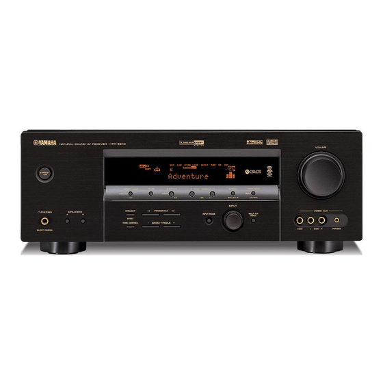
Yamaha RX-V459 Service Manual
Av receiver / av amplifier
Hide thumbs
Also See for RX-V459:
- Owner's manual (93 pages) ,
- Owner's manual (111 pages) ,
- Service manual (99 pages)
Advertisement
AV RECEIVER/AV AMPLIFIER
RX-V459/HTR-5940
This manual has been provided for the use of authorized YAMAHA Retailers and their service personnel.
It has been assumed that basic service procedures inherent to the industry, and more specifically YAMAHA Products, are already
known and understood by the users, and have therefore not been restated.
WARNING:
IMPORTANT:
The data provided is believed to be accurate and applicable to the unit(s) indicated on the cover. The research, engineering, and
service departments of YAMAHA are continually striving to improve YAMAHA products. Modifications are, therefore, inevitable
and specifications are subject to change without notice or obligation to retrofit. Should any discrepancy appear to exist, please
contact the distributor's Service Division.
WARNING:
IMPORTANT:
I CONTENTS
自己診断機能 (ダイアグ) ........................................
PIN CONNECTION DIAGRAM ..............................
1 0 0 9 9 8
IMPORTANT NOTICE
Failure to follow appropriate service and safety procedures when servicing this product may result in personal
injury, destruction of expensive components, and failure of the product to perform as specified. For these reasons,
we advise all YAMAHA product owners that any service required should be performed by an authorized
YAMAHA Retailer or the appointed service representative.
The presentation or sale of this manual to any individual or firm does not constitute authorization, certification or
recognition of any applicable technical capabilities, or establish a principle-agent relationship of any form.
Static discharges can destroy expensive components. Discharge any static electricity your body may have
accumulated by grounding yourself to the ground buss in the unit (heavy gauge black wires connect to this buss).
Turn the unit OFF during disassembly and part replacement. Recheck all work before you apply power to the unit.
2006
This manual is copyrighted by YAMAHA and may not be copied or
redistributed either in print or electronically without permission.
SERVICE MANUAL
All rights reserved.
P.O.Box 1, Hamamatsu, Japan
'06.02
Advertisement
Table of Contents

Summary of Contents for Yamaha RX-V459
-
Page 1: Service Manual
This manual has been provided for the use of authorized YAMAHA Retailers and their service personnel. It has been assumed that basic service procedures inherent to the industry, and more specifically YAMAHA Products, are already known and understood by the users, and have therefore not been restated. - Page 2 • Starting DIAG ● ダイアグの起動 Press the “STANDBY/ON” key while simultaneously 本体の下図に示すキーを同時に押しながら “STANDBY/ON” pressing those two keys of the main unit as indicated in the キーを押すと、ダイアグが起動します。 figure below. Keys of main unit / 本体キー Turn on the power while pressing these keys. これらのキーを同時に押しながら、パワーオンする。...
- Page 3 SN74LV157APWR SN74LV245APWR TRAN TC4013BP FF W9816G6CH-7 SDRAM YAC520-EE2 SN74LVU04APWR TC74VHCU04FT INVER S29AL004D70TF1020 • Diodes MA8082-H 8.5V 1N4002S RB441Q-40 T-77 D2SBA20 1.5A 200V MA8030-L 2.9V RB500V-40 1SS133,176 RB441Q-40 T-77 D5SB20 5A 200V MA8051-M 5.1V RB501V-40 1SS270A MA8056-M 5.6V UDZ 3.6BTE-17 3.6V Anode 1SS355 MA8068-L 6.6V...
-
Page 4: Video Block Diagram
OUTPUT AMP LA73050 BYPASS IC401 CVBS INPUT SELECTOR 74HC4051 • See page 73 → CVBS DVR OUT DTV/CBL OPERATION SCHEMATIC DIAGRAM CVBS IC402 RX-V459, V-AUX DSP-AX459, HTR-5940 models CVBS DTV/CBL IC403 RX-V459, IC404 DSP-AX459, RX-V459, HTR-5940 DSP-AX459, models HTR-5940 models... -
Page 5: Control/Power Block Diagram
CONTROL/POWER BLOCK DIAGRAM POWER • See page 69-71 → TRANSFORMER /4ohms SCHEMATIC DIAGRAM RY105 OPERATION • See page 73 → SCHEMATIC DIAGRAM LIMITER CONTROL IR REMOTE RY105 U3000 POWER RELAY 51/ 50/ 49/ 48/ 46 SPEAKER RELAY VOLUME 63/ 64 100- 104 MUTE CONTROL SW300... - Page 6 DSP 2/3 IC61, 62 : SN74AHCT1G32DCKR IC63 : SN74AHCT08PWR Single 2-input positive-OR gate Quadruple 2-input positive-AND gates POINT A-1 Pin 28 of IC55 POINT A-2 Pin 29 of IC56 IC64 : W9816G6CH -7 512K x 2 banks x 16 bits SDRAM CLK 35 CLOCK BUFFER...
- Page 7 DSP 3/3 Page 72 Page 74 to FUNCTION (1)_CB202 to MAIN (2)_W1004 IC71-74, 75, 76 : NJM4565M Dual operational amplifier 2, 6 –INPUT OUTPUT 1, 7 +INPUT 3, 5 V– LC89057W-VF4A-E LC89057W-VF4AD-E ANALOG IN IC70 : PCM1803DBR Stereo A/D converter 11.8 Delta-Sigma Modulator...
-
Page 8: Input Selector
FUNCTION Page 71 Page 73 Page 69 to DSP_CB56 to OPERATION (5)_W3007 to DSP_CB1 -6.9 EXTENSION SELECTOR Page 69 Page 73 IC200 : BD3816K1 to DSP_CB2 to OPERATION (2)_CB252 7-channel volume IC for 7-channel LOGIC AGND1 VINFR INA1 GOUTFL SURROUND BACK L/R INA2 VINFL... - Page 9 FUNCTION (3)_W3005A,W3005B VIN1 +VCC1 +Vcc DCCNT1 VOUT1 Page 74 Page 72 Page 72 to MAIN (2)_W1006 to FUNCTION (2)_CB290 to FUNCTION (1)_CB201 VIN2 VOUT2 RX-V459/DSP-AX459 models MUTE1 N.C. VIN3 VOUT3 RX-V459/DSP-AX459 models N.C. -VCC1 220K N.C. -VCC2 N.C. N.C. VIN4...
- Page 10 -57.2 -60.1 Low dropout voltage regulator with ON/OFF control Page 72 -57.2 -57.7 to FUNCTION (1)_CB207 -58.3 Vout 58.8 59.9 58.2 59.9 no use(RX-V459/DSP-AX459 models) Page 72 59.6 58.2 59.3 Bandgrap 4.7/50 -0.4 Reference to FUNCTION (1)_CB206 -1.0 -0.6 ON/OFF -0.6...
- Page 11 HTR-5935 SUBWOOFER IC500 : NJM2068LD Dual operational-amplifier 2, 6 OUTPUT –INPUT 1, 7 +INPUT 3, 5 V– # All voltages are measured with a 10MΩ/V DC electronic volt meter. # Components having special characteristics are marked s and must be replaced with parts having specifications equal to those originally installed.
- Page 12 RX-V459/HTR-5940...


