Hitachi DV 14DSDL Service Manual
Hide thumbs
Also See for DV 14DSDL:
- Handling instructions manual (180 pages) ,
- Handling instructions manual (148 pages)
Advertisement
Quick Links
PRODUCT NAME
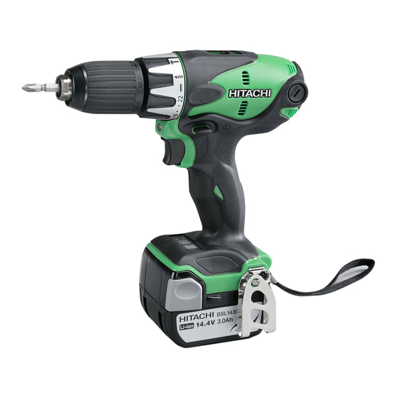
Hitachi 14.4 V Cordless Impact Driver Drill
DV 14DSDL
Model
Hitachi 18 V Cordless Impact Driver Drill
DV 18DSDL
Model
CONTENTS
REPAIR GUIDE ---------------------------------------------------------------------------------------------------------------- 1
1. Precautions on disassembly and reassembly ----------------------------------------------------------- 1
2. Precautions on disassembly and reassembly of battery charger ----------------------------------10
STANDARD REPAIR TIME (UNIT) SCHEDULES ------------------------------------------------------------------- 11
LIST No.
DV 14DSDL: J813
DV 18DSDL: J815
Jan. 2012
DV 18DSDL
International Sales Division
D
Page
Advertisement

Related Manuals for Hitachi DV 14DSDL


Summary of Contents for Hitachi DV 14DSDL
- Page 1 LIST No. DV 14DSDL: J813 DV 18DSDL: J815 Jan. 2012 PRODUCT NAME Hitachi 14.4 V Cordless Impact Driver Drill DV 14DSDL Model Hitachi 18 V Cordless Impact Driver Drill DV 18DSDL Model CONTENTS Page REPAIR GUIDE ---------------------------------------------------------------------------------------------------------------- 1 1. Precautions on disassembly and reassembly ----------------------------------------------------------- 1 2.
-
Page 2: Repair Guide
1. Precautions on disassembly and reassembly [Bold] numbers in the descriptions below correspond to item numbers in the Parts List and exploded assembly diagram for the Models DV 14DSDL and DV 18DSDL. Disassembly 1. Adjust the clutch dial to “... - Page 3 5. Removal of the drill chuck and drive unit (1) Attach the spindle lock jig (an accessory of special repair tool J-355) to the spindle of Front Case [10], and then mount it in special repair tool J-355 clamped in the vise as illustrated in Fig. 1. (2) Turn the sleeve of Drill Chuck 13VLRL-N [2] counterclockwise (as viewed from the front) to fully open the jaws of Drill Chuck 13VLRL-N [2].
- Page 4 Reassembly Reassembly can generally be conducted by reversing the disassembly procedure. However, special attention should be given to the following items. 1. Reassembly of the power supply unit Perform wiring according to the wiring diagram (Fig. 2). Pay attention to the direction in which to connect the internal wires and terminals.
- Page 5 (3) When mounting the DC-Speed Control Switch [50] in housing (A), fit the protrusion of the forward/reverse changeover lever on top of the DC-Speed Control Switch [50] into the hole groove of the Pushing Button [48]. (4) Pass the internal wire connected to the LED light between the housing ribs as shown in Fig. 3. (5) Pass the internal wire connected to the DC-Speed Control Switch [50] between the ribs as shown in Fig.
- Page 6 2. Reassembly of the clutch unit (1) Mount the Stopper Spring [29], Stopper (A) [28], Sleeve [9], and Spring [8] to the Front Case [10] in this order (Fig. 4). Fig. 4 Sleeve [9] Spring [8] Front Case [10] Stopper (A) [28] Stopper Spring [29] (2) Screw the Nut [7] into the Front Case [10] (Fig.
- Page 7 3. Reassembly of the gear unit Fig. 6 (1) Mount Washer (A) [13], Lock Ring (A) [14], and Front Case [10] the Lock Cam [16] to the Front Case [10]. Protrusion The protrusion of Lock Ring (A) [14] aligns with Lock Ring (A) [14] the concave portion of the Front Case [10] Lock Cam [16]...
- Page 8 4. Reassembly of the armature unit (1) Mounting the Motor Spacer [35] Mount the Motor Spacer [35] to the Armature and Pinion Set [36]. If mounting proves too difficult, use a hand press to support the Motor Spacer [35] and press down on the rear end of the armature shaft of the Armature and Pinion Set [36] (Fig.
- Page 9 (2) Mount the Shift Knob [49] and Shift Arm [22] Screw Set M3 x 12 (4 pcs.) [24] Fig. 11 Shift Arm [22] (Fig. 11). Mount the Shift Arm [22] to the cylindrical protrusions inside the Rear Case [21]. Insert the cylindrical protrusions of the Rear Case Left-handed [21] into the holes of the Shift Arm [22] on both...
- Page 10 6. Reassembly of the main unit (1) Mount the Lock Nut M4 (Black) [44] and Packing [45] to the Housing (A).(B) Set [41]. (2) Mount the power supply unit and drive unit that were reassembled in the procedure above to the Housing (A).(B) Set [41].
-
Page 11: Precautions On Disassembly And Reassembly Of Battery Charger
Drill Chuck 13VLRL-N [2] should be clockwise (as viewed from the rear). Use the battery to power the Model DV 14DSDL or DV 18DSDL on and off. Use a 12-mm dia. test bar to check that runout of Drill Chuck 13VLRL-N [2] is 0.8 mm or less at a position 110 mm away from the tip of the chuck. -
Page 12: Standard Repair Time (Unit) Schedules
STANDARD REPAIR TIME (UNIT) SCHEDULES Variable MODEL 60 min. Fixed Work Flow DV 14DSDL Housing (A).(B) Set DV 18DSDL General Assembly Armature Pinion Set Controller Terminal DC-Speed Control Switch Pushing Button Magnet Shift Knob Gear Box Drill Chuck Ass’y Dial... - Page 13 LIST NO. J813 CORDLESS IMPACT DRIVER DRILL 2012 · 1 · 12 Model DV 14DSDL (E1)
- Page 14 PARTS DV 14DSDL ITEM ITEM CODE NO. CODE NO. DESCRIPTION REMARKS USED USED 995-344 FLAT HD. SCREW (A) (LEFT HAND) M6 X 25 323-898 DRILL CHUCK 13VLRL-N (W/O CHUCK WRENCH) 334-473 TAPPING SCREW (W/SP. WASHER) D3 X 20 (BLACK) 334-444...
- Page 15 PARTS DV 14DSDL ITEM CODE NO. DESCRIPTION REMARKS USED 313-687 TAPPING SCREW (W/FLANGE) D3 X 16 (BLACK) NAME PLATE 306-952 STRAP (BLACK) 329-083 BATTERY BSL 1430 (EUROPE, AUS, NZL) INCLUD. 505 334-419 BATTERY BSL 1440 (EUROPE, AUS, NZL) INCLUD. 505...
- Page 16 DV 14DSDL ITEM CODE NO. DESCRIPTION REMARKS USED - 4 - Printed in Japan 1 - 12 *ALTERNATIVE PARTS (120112N)
- Page 17 LIST NO. J815 CORDLESS IMPACT DRIVER DRILL 2012 · 1 · 12 Model DV 18DSDL (E1)
- Page 18 PARTS DV 18DSDL ITEM ITEM CODE NO. CODE NO. DESCRIPTION REMARKS USED USED 995-344 FLAT HD. SCREW (A) (LEFT HAND) M6 X 25 323-898 DRILL CHUCK 13VLRL-N (W/O CHUCK WRENCH) 334-473 TAPPING SCREW (W/SP. WASHER) D3 X 20 (BLACK) 334-444 COVER (A) 334-445 GEAR BOX ASS'Y...
- Page 19 PARTS DV 18DSDL ITEM CODE NO. DESCRIPTION REMARKS USED 313-687 TAPPING SCREW (W/FLANGE) D3 X 16 (BLACK) NAME PLATE 306-952 STRAP (BLACK) 330-068 BATTERY BSL 1830 (EUROPE, AUS, NZL) INCLUD. 505 334-421 BATTERY BSL 1840 (EUROPE, AUS, NZL) INCLUD. 505 330-067 BATTERY BSL 1830 (USA, CAN) INCLUD.
- Page 20 DV 18DSDL ITEM CODE NO. DESCRIPTION REMARKS USED - 4 - Printed in Japan 1 - 12 *ALTERNATIVE PARTS (120112N)