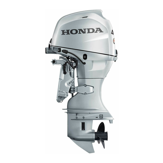
Honda bf50d Owner's Manual
Hide thumbs
Also See for bf50d:
- Manual (737 pages) ,
- Owner's manual (159 pages) ,
- Owner's manual (158 pages)
Table of Contents
Advertisement
Quick Links
Advertisement
Table of Contents

Related Manuals for Honda bf50d


Summary of Contents for Honda bf50d
- Page 1 Click to Save As Includes US and Canadian Models...
- Page 2 The information and specifications included in this publication were in effect at the time of approval for printing. Honda Motor Co., Ltd. reserves the right, however, to discontinue or change specifications or design at any time without notice and without incurring any obligation whatever.
- Page 3 INTRODUCTION Congratulations on your selection of We suggest you read the warranty a Honda outboard motor. We are policy to fully understand its certain you will be pleased with your coverage and your responsibilities of purchase of one of the finest outboard ownership.
- Page 4 INTRODUCTION A FEW WORDS ABOUT You will find important safety information in a variety of forms, including: SAFETY • Safety Labels – on the outboard motor. Your safety and the safety of others are very important. And using this • Safety Messages – preceded by a safety alert symbol and one of three outboard motor safely is an important signal words, DANGER, WARNING, or CAUTION.
-
Page 5: Table Of Contents
CONTENTS OUTBOARD MOTOR SAFETY ........7 Gearshift/Throttle Control Lever ......26 IMPORTANT SAFETY INFORMATION ....7 Fast Idle Lever .............27 SAFETY LABEL LOCATIONS ......9 LHT, LRT and XRT Types (power trim/tilt) Power Trim/Tilt Switch ........28 CONTROLS AND FEATURES ........13 Power Tilt Switch (engine pan) ......28 CONTROL AND FEATURE IDENTIFICATION Manual Relief Valve ..........29... - Page 6 CONTENTS INDICATORS ............32 OPERATION ..............44 Alternator (ACG) Indicator ......... 32 SAFE OPERATING PRECAUTIONS ....44 Malfunction Indicator .......... 32 BREAK-IN PROCEDURE ........44 Oil Pressure Indicator .......... 33 TRANSOM ANGLE ADJUSTMENT (LH Type) ...45 Overheat Indicator ..........34 PORTABLE FUEL TANK Cooling System Indicator ........
- Page 7 CONTENTS CRUISING .............. 63 Fuel Filter/Water Separator Inspection and TRIM TAB .............. 66 Service .............87 SHALLOW WATER OPERATION ...... 66 Portable Fuel Tank and Tank Filter Cleaning MOORING, BEACHING, LAUNCHING ..... 68 [standard equipment (Canadian types)], MULTIPLE OUTBOARD MOTORS ....69 [optional equipment (American types)] ..90 Anode Replacement ..........91 SERVICING YOUR OUTBOARD MOTOR ....
- Page 8 Electric Starter Will Not Operate ...... 108 Battery Will Not Charge ........108 CONSUMER INFORMATION ........124 Fuse Replacement ..........109 Honda Publications ..........124 OIL PRESSURE INDICATOR GOES OFF AND Customer Service Information .......124 ENGINE SPEED IS LIMITED ......110 Warranty Statements ..........127 OVERHEAT INDICATOR COMES ON AND Distributor’s Limited Warranty ......127...
-
Page 9: Outboard Motor Safety
INFORMATION • It is the operator’s responsibility to provide the necessary safeguards to • Always wear a PFD (Personal The Honda BF40D/BF50D outboard protect people and property. Flotation Device) while on the motors are designed for use with Know how to stop the engine boat. - Page 10 OUTBOARD MOTOR SAFETY Refuel With Care Carbon Monoxide Hazard • Gasoline is extremely flammable, Exhaust contains poisonous carbon and gasoline vapor can explode. monoxide, a colorless, odorless gas. Refuel outdoors, in a Breathing carbon monoxide can well-ventilated area, with the cause loss of consciousness and may engine stopped.
-
Page 11: Safety Label Locations
The label shown here contains important safety information. Please read it carefully. This label is considered a permanent part of your outboard motor. If the label comes off or becomes hard to read, contact an authorized Honda Marine dealer for a replacement. - Page 12 The label shown here contains important safety information. Please read it carefully. This label is considered a permanent part of your outboard motor. If the label comes off or becomes hard to read, contact an authorized Honda Marine dealer for a replacement.
- Page 13 OUTBOARD MOTOR SAFETY PORTABLE FUEL TANK [standard equipment (Canadian types)] [optional equipment (American types)] FUEL CAUTION...
- Page 14 • Gasoline is harmful or fatal if the area is dry before starting swallowed. Keep the fuel the engine. tank out of reach of children. • Honda outboard motor is • Gasoline is extremely designed to give safe and flammable and is explosive dependable service if under certain conditions.
-
Page 15: Controls And Features
CONTROLS AND FEATURES CONTROL AND FEATURE IDENTIFICATION CODES Model BF40D BF50D Type LRTA LRTC LHTC LRTA LRTC XRTA ● ● ● ● ● ● Shaft Length ● Tiller Handle ● ● Remote Control ● ● ● ● ● Gas Assist Tilt ●... -
Page 16: Component And Control Locations
CONTROLS AND FEATURES COMPONENT AND CONTROL LOCATIONS LH and LHT Types (tiller handle) SPARK PLUG POWER TRIM/ (inside the cover) ENGINE OIL TILT SWITCH FILLER CAP (LHT type only) ENGINE COVER ENGINE COVER LATCH (front) ENGINE COVER LATCH (rear) OIL LEVEL DIPSTICK TILLER HANDLE... - Page 17 CONTROLS AND FEATURES INDICATORS (Oil pressure, Overheat, Alternator, Malfunction) EMERGENCY STOP SWITCH GEARSHIFT LEVER THROTTLE FRICTION EMERGENCY STOP ADJUSTER SWITCH LANYARD THROTTLE GRIP EMERGENCY STOP SWITCH CLIP IGNITION SWITCH POWER TRIM/TILT SWITCH STEERING FRICTION (LHT type only) ADJUSTER IGNITION SWITCH KEY...
- Page 18 CONTROLS AND FEATURES LRT and XRT Types (remote control) SPARK PLUG (inside the cover) ENGINE OIL FILLER CAP ENGINE COVER ENGINE COVER LATCH (front) ENGINE COVER LATCH (rear) OIL LEVEL DIPSTICK TILT LOCK POWER FUEL LINE COOLING LEVER TILT CONNECTOR SYSTEM SWITCH INDICATOR...
- Page 19 CONTROLS AND FEATURES Remote Control Box Side-Mount Control Type [standard equipment (LRTC type)], [optional equipment (LRTA and XRTA types)] GEARSHIFT/THROTTLE CONTROL LEVER NEUTRAL RELEASE LEVER POWER TRIM/TILT SWITCH INDICATORS (Oil pressure, Overheat, Alternator, Malfunction) FAST IDLE LEVER SPARE EMERGENCY STOP SWITCH CLIP IGNITION SWITCH IGNITION SWITCH BUZZER...
- Page 20 CONTROLS AND FEATURES Portable Fuel Tank [standard equipment (Canadian types)] [optional equipment (American types)] FUEL GAUGE PORTABLE FUEL TANK VENT KNOB FUEL FILLER CAP FUEL HOSE (standard equipment) FUEL HOSE CONNECTOR (female) PRIMING BULB...
- Page 21 CONTROLS AND FEATURES Trim Meter Tachometer [standard equipment (Canadian [standard equipment (Canadian types)] types)] [optional equipment (LRTA and [optional equipment (LRTA and XRTA types)] XRTA types)] Trolling Control Switch Panel [optional equipment (other LHA and LHTC types)] TRL (Trolling) CONTROL SWITCH...
-
Page 22: Controls
CONTROLS AND FEATURES CONTROLS Turning the ignition switch key to the Emergency Stop Switch Clip and START position operates the starter Emergency Stop Switch motor. The key automatically returns LH and LHT Types to the ON position when released (tiller handle) EMERGENCY STOP SWITCH from the START position. -
Page 23: Throttle Grip
CONTROLS AND FEATURES The emergency stop switch clip must Throttle Grip The throttle grip controls engine be inserted in the emergency stop speed. switch in order for the engine to start The throttle index mark shows and run. The emergency stop switch throttle position and is helpful for lanyard must be attached securely to setting the throttle correctly when... -
Page 24: Throttle Friction Adjuster
CONTROLS AND FEATURES Throttle Friction Adjuster Gearshift Lever Steering Friction Adjuster THROTTLE FRICTION N (neutral) STEERING FRICTION ADJUSTER ADJUSTER (forward) R (reverse) TO INCREASE TO DECREASE RELEASE FRICTION FRICTION (LOCK) (FREE ) THROTTLE GRIP GEARSHIFT LEVER The throttle friction adjuster adjusts The gearshift lever is used to select F The steering friction adjuster adjusts resistance to throttle grip rotation. -
Page 25: Transom Angle Adjusting Rod
CONTROLS AND FEATURES Transom Angle Adjusting Rod The transom angle adjusting rod Tilt Lever (LH type) limits the tilt angle of the outboard (LH type) motor when fully lowered. STERN BRACKET Proper adjustment prevents the FREE outboard motor from being trimmed TURN UP (TILT) too low (p. -
Page 26: Lrt And Xrt Types
CONTROLS AND FEATURES LRT and XRT Types Ignition Switch Turning the ignition switch key to the START position operates the starter (remote control/side-mount motor. The key automatically returns control type) to the ON position when released [standard equipment (LRTC from the START position. type)] START [optional equipment (LRTA and... -
Page 27: Emergency Stop Switch Clip And Emergency Stop Switch
CONTROLS AND FEATURES Emergency Stop Switch Clip and The emergency stop switch clip must be inserted in the emergency stop Emergency Stop Switch switch in order for the engine to start and run. The emergency stop switch EMERGENCY STOP SWITCH lanyard must be attached to the operator’s PFD (Personal Flotation Device) or to the operator securely. -
Page 28: Gearshift/Throttle Control Lever
CONTROLS AND FEATURES Gearshift/Throttle Control Lever N (NEUTRAL) 30° 30° F (FORWARD) GEARSHIFT/THROTTLE R (REVERSE) CONTROL LEVER SHIFT SHIFT MINIMUM MINIMUM THROTTLE OPENING THROTTLE OPENING MAXIMUM MAXIMUM NEUTRAL GEARSHIFT/THROTTLE RELEASE LEVER CONTROL LEVER Moving the control lever 30° from N A friction adjuster near the base of The gearshift/throttle control lever (neutral) selects the gear, and further... -
Page 29: Fast Idle Lever
CONTROLS AND FEATURES Fast Idle Lever N (neutral) MAXIMUM FAST IDLE START (LOWEST POSITION) FAST IDLE LEVER Use the fast idle lever to accelerate The fast idle lever allows you to engine warm-up after starting the increase the idle speed only when the engine. -
Page 30: Lht, Lrt And Xrt Types (Power Trim/Tilt)
CONTROLS AND FEATURES LHT, LRT and XRT Types The power trim/tilt switch is located Power Tilt Switch (engine pan) on the control lever. It is a rocker (power trim/tilt) switch with UP and DN (down) positions for changing the angle of Power Trim/Tilt Switch the outboard motor. -
Page 31: Manual Relief Valve
CONTROLS AND FEATURES Manual Relief Valve The outboard motor can be tilted Except LHA and LHTC types manually after opening the manual TRL (Trolling) Control Switch relief valve. This allows the outboard [optional equipment ] RIGHT STERN BRACKET motor to be tilted up or down when SWITCH PANEL no battery is connected. -
Page 32: Common Controls
CONTROLS AND FEATURES Common Controls Engine Cover Latches Trim Tab TRIM TAB BOLT Tilt Lock Lever (front) TILT LOCK LEVER FREE ENGINE TRIM TAB COVER LATCH UNLATCH LOCK PROPELLER (rear) The tilt lock lever is used to support The trim tab compensates for ‘‘torque the outboard motor in the fully-raised steer,’’... -
Page 33: Instruments
CONTROLS AND FEATURES INSTRUMENTS Tachometer Fuel Gauge [standard equipment (Canadian [standard equipment (Canadian types)] types)] Trim Meter [optional equipment (LRTA and [optional equipment (American [standard equipment (Canadian XRTA types)] types)] types)] [optional equipment (LRTA and FUEL GAUGE XRTA types)] A fuel gauge is built into the fuel tank connector of the portable fuel tank. -
Page 34: Indicators
ACG INDICATOR MALFUNCTION develops a problem. Have your INDICATOR Honda Marine dealer check for burned-out bulbs or other problems. (internal buzzer) Under normal conditions, the following occur when the ignition LRT and XRT Types... -
Page 35: Oil Pressure Indicator
CONTROLS AND FEATURES When the engine control system Oil Pressure Indicator When the oil pressure indicator is lit, detects an engine control system oil pressure is OK. LH and LHT Types malfunction, the malfunction If oil pressure becomes low, the indicator turns on and the buzzer indicator will go off, and the engine sounds at one-second intervals. -
Page 36: Overheat Indicator
CONTROLS AND FEATURES Overheat Indicator When the alert triggers, the overheat Cooling System Indicator indicator comes on and the buzzer LH and LHT Types sounds a steady tone as the engine speed is reduced to 1,800 rpm. If the (RED) condition persists for another 20 seconds, the engine shuts off. -
Page 37: Other Features
CONTROLS AND FEATURES The cooling system indicator OTHER FEATURES Portable Fuel Tank discharge port can also become [standard equipment (Canadian plugged. types)] Overrev Limiter [optional equipment (American The engine is equipped with an types)] overrev limiter to prevent the possibility of mechanical damage from excessive engine speed. -
Page 38: Fuel Filler Cap Vent Knob
CONTROLS AND FEATURES Fuel Filler Cap Vent Knob Fuel Priming Bulb NMEA Interface Coupler ® The NMEA2000 interface coupler VENT KNOB can provide information regarding OPEN engine speed, fuel consumption, and various warnings to an existing OUTLET END NMEA2000 network via an optional (outboard motor side) interface cable. -
Page 39: Operating Hour Notification System
CONTROLS AND FEATURES Operating Hour Notification Periodic maintenance is required when either the operating hours or the System time since last maintenance reaches This outboard motor engine counts the prescribed limit. Therefore, the number of operating hours since periodic maintenance may be the last periodic maintenance. - Page 40 CONTROLS AND FEATURES <Operating hour notification timing> NMEA2000-compatible display: • Follow instructions for the display. • If the display allows selection of notification to be preset, select Every 100 hours ‘‘Notify’’ (or equivalent). • Turn on the power supply to the 80 hours 100 hours display before turning on the...
- Page 41 CONTROLS AND FEATURES When ‘‘Periodic Maintenance’’ is indicated: 1. Have the periodic maintenance performed without delay after returning to port. 2. Reset the hour counter. If not reset, the maintenance indication will remain in the display, and the hour count until the next maintenance will be in error.
-
Page 42: Anodes
CONTROLS AND FEATURES Anodes ANODE (stern bracket) ANODE (each side) The anodes are made of a sacrificial material that helps to protect the outboard motor from corrosion. There are two anodes on the gear case, one on the stern bracket and two small anodes in the water passages of the engine block. -
Page 43: Before Operation
Be sure to take care of any problem Familiarize yourself with all laws and you find, or have your authorized regulations relating to boating and the Honda Marine dealer correct it, use of outboard motors. before you operate the outboard motor. -
Page 44: Maintenance Inspection
BEFORE OPERATION Safety Inspection • Check that all fasteners are in place • Make sure a tool kit and the and securely tightened. emergency starter rope are onboard • Before each use, look around (p. 72). Replace any missing items. underneath the engine for signs of •... -
Page 45: Tiller Handle Height/Angle Adjustment (Lh And Lht Types)
BEFORE OPERATION Tiller Handle Height/Angle Install the height adjustment block Adjustment (LH and LHT so that the selected angle of the tiller handle is in this position. types) 13.2 in HANDLE ANGLE: 7° (336 mm) HANDLE ANGLE: 21° HANDLE ANGLE: 13° HANDLE ANGLE: 13°... -
Page 46: Operation
OPERATION SAFE OPERATING BREAK-IN PROCEDURE Next 60 minutes: Run the engine up to a maximum of PRECAUTIONS 4,000 to 5,000 rpm, which is about Break-in period: 10 hours To safely realize the full potential of 50% to 80% of maximum throttle this outboard motor, you need a opening. -
Page 47: Transom Angle Adjustment (Lh Type)
OPERATION TRANSOM ANGLE The transom angle adjusting rod limits the tilt angle of the outboard ADJUSTMENT (LH Type) Do not allow water to enter the idle motor when fully lowered. exhaust port or the engine can be STERN BRACKET damaged. Proper adjustment prevents the outboard motor from being trimmed TURN UP... -
Page 48: Portable Fuel Tank
OPERATION PORTABLE FUEL TANK Secure the portable fuel tank in the FUEL HOSE CONNECTIONS boat so that it won’t move around and [standard equipment (Canadian Turn the portable fuel tank vent knob become damaged. types)] counterclockwise to the open [optional equipment (American position. -
Page 49: Fuel Priming
OPERATION Connect the fuel hose to the tank and FUEL PRIMING Do not touch the priming bulb with the outboard motor, as shown. Be the engine running or when tilting up If you are using a portable fuel tank, sure both connectors snap securely the outboard motor. -
Page 50: Infrequent Or Occasional Use
OPERATION INFREQUENT OR STARTING THE ENGINE 1. Put the emergency stop switch clip in the emergency stop switch, and OCCASIONAL USE Control Page attach the emergency stop switch Side-Mount Control Type ... 51 If your outboard motor will be used lanyard securely to the operator or on an infrequent or intermittent basis, to the operator’s PFD (Personal... - Page 51 OPERATION N (neutral) START START POSITION POINTER GEARSHIFT LEVER IGNITION SWITCH KEY THROTTLE GRIP 2. Check the position of the gearshift 3. Align the engine start symbol 4. Turn the ignition switch key to the lever. It must be in the N (neutral) ON position;...
- Page 52 OPERATION If the engine fails to start within 5 6. Before getting underway, allow the seconds, release the key and wait at engine to warm-up sufficiently to • If the engine is not properly least 10 seconds before operating ensure good performance. warmed up before raising the the starter again.
-
Page 53: Lrt And Xrt Types (Remote Control)
OPERATION LRT and XRT Types The engine will not start or run unless the emergency stop switch (remote control) clip is in the emergency stop N (neutral) switch. Side-Mount Control Type [standard equipment (LRTC The emergency stop switch clip type)] and emergency stop switch lanyard [optional equipment (LRTA and system is a safety device that will... - Page 54 OPERATION If the engine fails to start within 5 seconds, release the key and wait at START least 10 seconds before operating the starter again. FAST IDLE RANGE START • Using the electric starter for more (fully lowered) than 5 seconds at a time will overheat the starter motor and can damage it.
- Page 55 OPERATION During the warm-up period, check the oil pressure indicator (p. 33), • If the engine is not properly MAXIMUM FAST IDLE overheat indicator (p. 34), and warmed up before raising the cooling system indicator (p. 34). engine speed, the buzzer and FAST IDLE RANGE overheat indicator may activate...
-
Page 56: Emergency Starting
OPERATION EMERGENCY STARTING 6 × 25 mm BOLTS (rear) If the battery is discharged or the Remove starter motor is inoperative, you can the band start the engine manually using the clamp. Release emergency starter rope supplied with the harness. the outboard motor. - Page 57 OPERATION If necessary, rewind the rope and 5. Set the controls the same as for normal starting (p. 48 – 49, pull again. If the engine does not 51 – 52). start after several attempts, refer to TAKING CARE OF Direction to pull Turn the ignition switch key to the UNEXPECTED PROBLEMS on...
- Page 58 (p. 34), and cooling system indicator (p. 34). 11. Have your closest authorized Honda Marine dealer check your 9. Leave the alternator cover off, but electrical system and correct the install the engine cover (p. 76) and...
-
Page 59: Stopping The Engine
OPERATION STOPPING THE ENGINE LRT and XRT Types To stop the engine in an emergency, pull the emergency stop switch clip (remote control) out of the emergency stop switch by Emergency Engine Stopping pulling the emergency stop switch EMERGENCY STOP SWITCH lanyard. -
Page 60: Normal Engine Stopping
OPERATION Normal Engine Stopping LRT and XRT Types After cruising at full throttle, cool down the engine by idling for a few (remote control) minutes before stopping the engine. LH and LHT Types (tiller handle) Side-Mount Control Type N (neutral) SLOW CONTROL LEVER... - Page 61 OPERATION LH and LHT Types 2. Turn the ignition switch key to the OFF position to stop the engine. In (tiller handle) the event that the engine does not stop when the ignition switch key is turned to the OFF position, pull the emergency stop switch clip out of the emergency stop switch by pulling the emergency stop switch...
-
Page 62: Gearshift And Throttle Operation
OPERATION GEARSHIFT AND To shift gears, turn the throttle grip to THROTTLE FRICTION ADJUSTER the SLOW position; then move the THROTTLE OPERATION THROTTLE gearshift lever to select the F GRIP (forward), N (neutral), or R (reverse) LH and LHT Types gears. -
Page 63: Lrt And Xrt Types (Remote Control)
OPERATION LRT and XRT Types To shift gears, move the control lever to select the F (forward), N (neutral), (remote control) or R (reverse) gear. CONTROL LEVER The control lever cannot be moved TO INCREASE from the N (neutral) position unless FRICTION the neutral release lever is squeezed. -
Page 64: Steering
OPERATION STEERING Steering Friction Adjuster LRT and XRT Types (remote control) FRICTION STEERING FRICTION PLATE ADJUSTER LH and LHT Types Steer the boat in the same manner as (tiller handle) an automobile. RIGHT TURN LEFT TURN TO INCREASE TO DECREASE FRICTION FRICTION (LOCK) -
Page 65: Cruising
OPERATION CRUISING If engine speed becomes unstable at antiventilation plate is level with the high speed due to activation of the water surface. overrev limiter, reduce speed and Engine Speed When cruising into a high wind, trim check the trim angle of the outboard the outboard motor down slightly to motor. - Page 66 OPERATION It is necessary to trim the angle of the LHT Type OUTBOARD OUTBOARD outboard motor to compensate for MOTOR MOTOR TRIMMED TOO TRIMMED TOO changes in boat load, weight HIGH distribution, water conditions, or propeller selection. Press UP to trim or tilt the outboard Under normal conditions, the boat motor up.
- Page 67 OPERATION Trolling Speed Control DN: Reduce engine speed RPM, the Trolling Speed Control is UP: Increase engine speed deactivated. If 3,000 RPM is not [optional equipment (except reached and the throttle is closed, the LHA and LHTC types)] Place the outboard motor in-gear with engine speed will decrease to the SWITCH PANEL the throttle control in the fully closed...
-
Page 68: Trim Tab
OPERATION TRIM TAB Refer to TRIM TAB ADJUSTMENT LH Type on p. 75. If steering effort is not equal in both When operating in shallow water, tilt directions, adjust the trim tab to SHALLOW WATER the outboard motor, using the tilt compensate for ‘‘torque steer,’’... - Page 69 OPERATION While the outboard motor is tilted, To return the outboard motor to the ENGINE COVER GRIP proceed at a low speed, and do not normal operating position, move the operate the outboard motor in tilt lever to the LOCK (RUN) reverse.
-
Page 70: Mooring, Beaching, Launching
OPERATION MOORING, BEACHING, Move the tilt lock lever to the LOCK TILT LOCK LEVER position, and then gently lower the LAUNCHING (lock position) outboard motor until the lever Before tilting up, leave the outboard contacts the stern bracket. motor in the running position for one FREE If more clearance is needed to swing minute after stopping the engine to... -
Page 71: Multiple Outboard Motors
OPERATION Check that nobody is under the MULTIPLE OUTBOARD outboard motor before opening the MOTORS MANUAL RELIEF manual relief valve. If the manual VALVE relief valve is loosened (turned On boats equipped with more than counterclockwise) when the outboard one outboard motor, all motors motor is tilted up, the outboard motor normally operate at the same time. -
Page 72: Servicing Your Outboard Motor
Genuine parts or their equivalents for special tools are best handled by repair and replacement. professionals and are normally performed by a Honda technician or Improperly maintaining this Maintenance, replacement, or other qualified mechanic. outboard motor or failure to... -
Page 73: Maintenance Safety
SERVICING YOUR OUTBOARD MOTOR MAINTENANCE SAFETY Safety Precautions • Read the instructions before you begin, and make sure you have the Some of the most important safety • Make sure the engine is off before tools and skills required. precautions follow. However, we you begin any maintenance or •... -
Page 74: Spare Switch Clip And Emergency Starter Rope
SERVICING YOUR OUTBOARD MOTOR SPARE SWITCH CLIP (LH TOOL KIT and OWNER’S MANUAL and LHT Types) AND EMERGENCY STARTER ROPE 18 × 19 mm 8 × 10 mm WRENCH SOCKET WRENCH FLAT SCREWDRIVER FUSE PULLER SPARE SWITCH CLIP GRIP (LH and LHT Types) OWNER’S MANUAL TOOL BAG The owner’s manual and tool kit can be used to perform simple maintenance... -
Page 75: Maintenance Schedule
(2) These items should be serviced by your servicing dealer, unless you have the proper tools and are mechanically proficient. Refer to the Honda shop manual for service procedures. See “Honda Publications” on page 124 for ordering information. (3) For professional commercial use, log hours of operation to determine proper maintenance intervals. - Page 76 (2) These items should be serviced by your servicing dealer, unless you have the proper tools and are mechanically proficient. Refer to the Honda shop manual for service procedures. See “Honda Publications” on page 124 for ordering information. (3) For professional commercial use, log hours of operation to determine proper maintenance intervals.
-
Page 77: Trim Tab Adjustment
SERVICING YOUR OUTBOARD MOTOR TRIM TAB ADJUSTMENT LEFT The trim tab compensates for ‘‘torque steer,’’ which is a reaction of the outboard motor to propeller rotation. RIGHT If uncompensated, torque steer would TRIM TAB make the outboard motor tend to turn TRIM TAB to one side. -
Page 78: Manual Relief Valve
SERVICING YOUR OUTBOARD MOTOR MANUAL RELIEF VALVE Check that nobody is under the (rear) outboard motor before opening the manual relief valve. If the manual LHT, LRT and XRT Types ENGINE COVER relief valve is loosened (turned LATCH counterclockwise) when the outboard MANUAL motor is tilted up, the outboard motor RELIEF VALVE... -
Page 79: Engine Oil Level Check
SERVICING YOUR OUTBOARD MOTOR Engine Oil Level Check OIL FILLER CAP Running the engine with a low oil Check the engine oil level with the level can cause engine damage. engine stopped and the outboard motor in the vertical position. 5. - Page 80 SERVICING YOUR OUTBOARD MOTOR When you check the oil level with the dipstick, you might notice the engine oil appears milky or the oil level has increased. If you notice either condition, change the engine oil. See the following table for an explanation of these conditions.
-
Page 81: Engine Oil Change
SERVICING YOUR OUTBOARD MOTOR Engine Oil Change An engine oil evacuation device may be used to remove the engine oil. DRAIN BOLT COVER Drain the used oil while the engine is warm. Warm oil drains quickly and completely. 1. Unlatch and remove the engine cover (p. - Page 82 SERVICING YOUR OUTBOARD MOTOR 7. With the outboard motor in a vertical position, fill to the upper SEALING Improper disposal of engine oil can WASHER limit mark on the dipstick (p. 77) be harmful to the environment. If you with the recommended oil. change your own oil, please dispose of the used oil properly.
-
Page 83: Engine Oil Recommendations
2. Disconnect the spark plug caps SAE 5W-30 is recommended for general use. from the spark plugs. Honda recommends that you use API 3. Remove the spark plugs with a service category SG, SH or SJ oil. spark plug wrench. - Page 84 SERVICING YOUR OUTBOARD MOTOR 6. Install the spark plugs carefully, by SIDE ELECTRODE hand, to avoid cross-threading. New plug Plug needing replacement 0.024 – 0.028 in (0.6 – 0.7 mm) 7. After each spark plug seats, tighten with a spark plug wrench to SEALING WASHER compress the sealing washer.
-
Page 85: Lubrication Points
To prevent corrosion, apply anticorrosion oil to pivot surfaces where grease cannot penetrate. UPPER SWIVEL CASE/ MOUNT FRAME PROPELLER SHAFT LOWER SWIVEL CASE Apply Honda Marine Corrosion Inhibitor (or equivalent) to all areas under the engine cover and any exposed metal surfaces except the belts. -
Page 86: Refueling
Wait to relieve fuel within a 30 day period, we VENT KNOB pressure. recommend adding Honda Marine FUEL FILLER CAP OPEN Fuel Stabilizer each time you refuel. Portable Fuel Tank... - Page 87 SERVICING YOUR OUTBOARD MOTOR Using the fuel tank mounted in SAFE FILL LEVEL the boat. Gasoline is highly flammable Check the fuel level and refill if and explosive. necessary. Do not fill the fuel tank You can be burned or above the UPPER LIMIT.
-
Page 88: Fuel Recommendations
SERVICING YOUR OUTBOARD MOTOR FUEL RECOMMENDATIONS Engine damage or performance problems that result from using a fuel Use unleaded gasoline with a pump with percentages of ethanol or octane rating of 86 or higher. methanol greater than shown above are not covered under warranty. Your outboard motor is certified to operate on unleaded gasoline. -
Page 89: Fuel Filter/Water Separator Inspection And Service
SERVICING YOUR OUTBOARD MOTOR Fuel Filter/Water Separator Inspection and Service Gasoline is highly flammable The fuel filter is located under the and explosive. engine cover between the fuel PULL You can be burned or coupling and the fuel pump. seriously injured when Water or sediment accumulation in handling fuel. - Page 90 SERVICING YOUR OUTBOARD MOTOR FUEL FILTER BRACKET FUEL FILTER CLAMP ASSEMBLY SUSPENSION STRAP FUEL HOSES FUEL FUEL FILTER FUEL FILTER HOSE CLIPS HOSES (inside strainer cup) (commercially available) (inside strainer cup) 2. Inspect the filter for water and/or 3. Remove the suspension strap from 5.
- Page 91 SERVICING YOUR OUTBOARD MOTOR Align the center of the filter FILTER BODY body and the arrow of the suspension strap rib. O-RINGS (Replace) FUEL FILTER FLOAT (red ring) SUSPENSION STRAP STRAINER CUP 9. Install the suspension strap to the 6. Unscrew the strainer cup from the 8.
-
Page 92: Portable Fuel Tank And Tank Filter Cleaning
SERVICING YOUR OUTBOARD MOTOR 11. Connect the fuel hoses to the fuel Portable Fuel Tank and Tank Fuel Tank filter securely with the hose Filter Cleaning clamps. Remove the fuel hose [standard equipment FUEL HOSE (standard equipment) clips used to close the fuel hoses. (Canadian types)] [optional equipment (American 12. -
Page 93: Anode Replacement
SERVICING YOUR OUTBOARD MOTOR Anode Replacement Fuel Tank Filter CONNECTOR 5 mm SCREWS (4) GASKET ANODE (each side) FUEL TANK FILLER FUEL TANK FILTER JOINT ANODE (Fuel Hose Connector) (stern bracket) 1. Remove the four 5 mm screws The anodes are located on each side using a flat screwdriver, then of the gear case and on the stern Painting or coating the anodes will... -
Page 94: Propeller Replacement
SERVICING YOUR OUTBOARD MOTOR Propeller Replacement 2. Inspect the propeller shaft for any Installation fishing line or debris. [standard equipment 1. Apply marine grade grease to the (Canadian types)] propeller shaft. [optional equipment (American types)] 2. Install the thrust washer with the grooved side toward the gear case. - Page 95 7. Be sure to replace the cotter pin spline washer and the plain washer. with a new one. 4. Lightly tighten the castle nut by • Use a Honda Genuine stainless hand or wrench until the propeller steel cotter pin or equivalent has no free play.
-
Page 96: Cleaning And Flushing
If water or corrosion inhibitor Touch up any damaged paint, and safety, remove the propeller from the penetrates these components, they coat areas that may rust with Honda outboard motor (p. 92). may be damaged. Before applying a Corrosion Inhibitor, or equivalent. - Page 97 CLEANING AND FLUSHING 6. Move the gearshift lever or control GARDEN HOSE ADAPTER lever to the N (neutral) position. (FLUSH KIT COUPLER) Flush the outboard motor in the neutral position only. 7. Turn on the fresh water supply to the flush kit coupler. WATER INTAKE Running the engine without good water circulation can cause...
- Page 98 CLEANING AND FLUSHING 9. Allow the engine to run at idle for at least 5 minutes to clean the inside of the outboard motor. 10. Stop the engine, and disconnect the fuel hose from the outboard motor. Remove the garden hose adapter.
-
Page 99: Storage
You can extend fuel storage life by adding fuel stabilizer. recommendations. adding a gasoline stabilizer that is 2. Add Honda Marine fuel stabilizer Gasoline will oxidize and deteriorate formulated for that purpose, or you following the instructions on the can avoid fuel deterioration problems in storage. - Page 100 STORAGE Draining the Fuel System 1. Disconnect the fuel hose connector from the outboard motor (p. 87). You can avoid fuel deterioration Gasoline is highly flammable problems by draining the fuel tank 2. Remove the engine cover (p. 76). and explosive. and vapor separator.
- Page 101 Honda Marine fuel stabilizer following a. Make sure the gasoline supply is the directions on the container.
-
Page 102: Engine Oil
STORAGE Engine Oil HOISTING THE OUTBOARD 4. After the outboard motor is placed in storage and disconnected from MOTOR 1. Change the engine oil (p. 79). the hoist, install the engine cover. 2. Remove the spark plugs (p. 81), STORAGE PRECAUTIONS and remove the emergency stop switch clip from the emergency Select a well-ventilated storage area. -
Page 103: Removal From Storage
STORAGE Any other horizontal storage position may cause damage to the outboard motor or oil leakage. CASE PROTECTOR Cover the outboard motor to keep out dust. Do not use plastic sheet as a dust cover. A nonporous cover will trap moisture, promoting rust and corrosion. -
Page 104: Transporting
TRANSPORTING WITH OUTBOARD MOTOR LRT and XRT Types WITH OUTBOARD MOTOR INSTALLED ON BOAT (remote control) REMOVED FROM BOAT When trailering a boat with the Use an outboard motor support bar to Secure the outboard motor in either outboard motor attached, always prevent the outboard motor from the vertical or horizontal position moving while trailering the boat. -
Page 105: Taking Care Of Unexpected Problems
TAKING CARE OF UNEXPECTED PROBLEMS ENGINE WILL NOT START Possible Cause Correction Clip not inserted in emergency stop switch. Insert clip in emergency stop switch. Gearshift lever or control lever not in neutral position. Shift to neutral (p. 48 or 51). Throttle grip not in START position (tiller handle type). - Page 106 TAKING CARE OF UNEXPECTED PROBLEMS ENGINE WILL NOT START Possible Cause Correction Out of fuel. Refuel (p. 84). Fuel vent closed (portable fuel tank). Open fuel filler cap vent (p. 36). Fuel hose not primed. Squeeze priming bulb (p. 47). Fuel filter or fuel tank filter clogged.
- Page 107 Use starting procedure (p. 48, 51); if engine still will not malfunction, stuck valves, starter malfunction, switch start, then take outboard motor to an authorized Honda malfunction, or electrical problem in the starting circuit, Marine dealer, or refer to the shop manual.
-
Page 108: Hard Starting Or Stalls After Starting
TAKING CARE OF UNEXPECTED PROBLEMS HARD STARTING OR STALLS AFTER STARTING Possible Cause Correction Throttle grip not in START position Turn throttle grip to START position (p. 49). (tiller handle type). Fast idle lever raised (remote control/side-mount type). Leave fast idle lever in the START position (p. 52). Fuel vent closed (portable fuel tank). -
Page 109: Engine Overheats
Spark plugs faulty, fouled, or improperly gapped. Gap or replace spark plugs (p. 81). Fuel system malfunction, fuel pump failure, ignition Take outboard motor to an authorized Honda Marine malfunction, etc. dealer, or refer to the shop manual. ENGINE OVERHEATS... -
Page 110: Fuses
TAKING CARE OF UNEXPECTED PROBLEMS FUSES SPARE FUSES (10 A, 15 A, 30 A) Electric Starter Will Not Operate The 10A, 15A, and 30A fuses protect the electric starter relay and related FUSES circuits. (10 A, 15 A, 30 A) The 10A (3) fuse protects the ignition switch and related circuits. -
Page 111: Fuse Replacement
2. Remove the engine cover. outboard motor to an authorized fuses. If a fuse is blown, install a Honda Marine dealer for inspection 3. Remove the fuse case lid. replacement fuse of the same speci- and service, or refer to the shop fied rating. -
Page 112: Oil Pressure Indicator Goes Off And Engine Speed Is Limited
TAKING CARE OF UNEXPECTED PROBLEMS OIL PRESSURE INDICATOR LRT and XRT Types GOES OFF AND ENGINE (remote control) SPEED IS LIMITED (GREEN) LH and LHT Types (tiller handle) (GREEN) BUZZER (internal buzzer) -
Page 113: Overheat Indicator Comes On And Engine Speed Is Limited
30 seconds, and the engine will respond normally to (internal buzzer) throttle control lever operation. If the engine protection system remains activated after 30 seconds, return to the nearest boat landing, and have the outboard motor inspected by an authorized Honda Marine dealer. - Page 114 30 seconds, return to the nearest boat landing, and have the outboard motor inspected by an authorized Honda Marine dealer.
-
Page 115: Submerged Outboard Motor
If there is a Honda Marine dealership nearby, take the outboard motor to the If the engine was running when it dealer immediately. If you are far... - Page 116 9. As soon as possible, take the the water level is at least 2 inches outboard motor to an authorized (5 cm) above the antiventilation Honda Marine dealer for inspection plate. and service. Running the outboard motor without sufficient cooling water will damage the water pump and overheat the engine.
-
Page 117: Technical Information
TECHNICAL INFORMATION Serial Number Locations ENGINE SERIAL NUMBER Record the product identification number, the engine serial number, and the date of purchase in the space provided on this page. You will need these numbers when ordering parts, and when making technical or warranty inquiries (p. -
Page 118: Battery
• Do not disconnect the battery terminals, and related accessories cables while the engine is running. Honda utilizes appropriate air/fuel contain lead and lead compounds. ratios and other emissions control Disconnecting the cables while the Wash your hands after handling. - Page 119 • Removal or alteration of any part to keep the emissions from your of the intake, fuel, or exhaust Honda engine within the emission systems. standards. • Alterations that would cause the engine to operate outside its design...
- Page 120 California emission regulations. machine will be used for its designed engine inspected and repaired by your We recommend the use of Honda purpose. Sustained high-load servicing dealer. Genuine parts whenever you have operation, or use in unusual •...
-
Page 121: Star Label
TECHNICAL INFORMATION Star Label The Star Label means Cleaner Marine Engine US, Puerto Rico, and US Virgin Islands This engine has been certified as a: A Star label was applied to this outboard motor in accordance with the requirements of the California Air Resources Board. - Page 122 TECHNICAL INFORMATION The one-star label identifies engines that meet the Air Resources Board’s One Star Personal Watercraft and Outboard marine engine 2001 exhaust emission standards. Engines meeting these standards have 75% lower emissions than Emission conventional carbureted two-stroke engines. These engines are equivalent to the U.S.
-
Page 123: Specifications
Tilt up angle Full transistor battery Ignition system 8°, 12°, 16°, 20°, 24° Transom angle Trochoid pump pressure lubrication Lubrication system * With propeller Honda outboard motors are power rated in accordance with NMMA procedures and using the ICOMIA standard 28/23. - Page 124 Starter system 8°, 12°, 16°, 20°, 24° Transom angle Full transistor battery Ignition system Trochoid pump pressure lubrication Lubrication system * With propeller Honda outboard motors are power rated in accordance with NMMA procedures and using the ICOMIA standard 28/23.
- Page 125 TECHNICAL INFORMATION BF40D/BF50D Tune-up 0.024 – 0.028 in (0.6 – 0.7 mm) See page 82 Spark plug gap 850 ± 50 rpm See shop manual Idle speed Intake: 0.15 ± 0.02 mm See shop manual Valve clearance Exhaust: 0.23 ± 0.02 mm...
-
Page 126: Consumer Information
Service Manager or the outboard motor. Visit http://marine.honda.com and dealership’s owner. click on PARTS & ACCESSORIES Shop Manual If you need to contact Honda to see the entire catalog of This manual covers complete regarding your experiences with your accessories. maintenance and overhaul Honda product or with your dealer, procedures. - Page 127 Warranty Coverage It is important to realize that your information in your communication: warranty applies to defects in Your new Honda is covered by the material or workmanship of your • Your name, address and telephone following warranties: Honda. Your warranty coverage does...
- Page 128 Service, Parts, or Sales department, etc.). contact the owner of the dealership or their designated representative. As the owner of a Honda product, your servicing dealer may ask you to authorize an inspection. If the problem is covered under warranty, your dealer will perform any warranty repairs for you at no cost.
-
Page 129: Warranty Statements
CONSUMER INFORMATION Warranty Statements The American Honda Distributor’s Limited Warranty applies to outboards purchased in the United States, Puerto Rico, or the U.S. Virgin Islands. The Honda Canada Distributor’s Warranty applies to outboards purchased in Canada. The product warranty is only valid in the country where the product was purchased. - Page 130 First, contact the owner of the dealership Warranty: involved; normally this should resolve the problem. American Honda will repair or replace, at its option, any However, if you should require further assistance, write or part that is proven to be defective in material or call the Honda Marine Customer Relations.
- Page 131 • Parts affected or damaged by an abuse, submersion and/ implied warranties: or collision American Honda disclaims any responsibility for loss of • Normal wear and tear time or use of the outboard, revenue, or the equipment in • Fuel contamination and water entering engine through...
- Page 132 CONSUMER INFORMATION Accessories and Replacement Parts This warranty is limited to Honda Marine parts, accessories and apparel when distributed by American Honda Motor Co., Inc., 1919 Torrance Blvd., Torrance, California 90501-2746. Products Covered by Warranty: Length of Warranty: (from date of original retail purchase)
- Page 133 To Obtain Warranty Service: written warranty. Some states do not allow limitations on You must, at your expense, take the Honda Outboard how long an implied warranty lasts and/or do not allow Motor product accessory or replacement part or the...
-
Page 134: Emission Control System Warranty
Emission Control System Warranty abuse, neglect, or improper maintenance of your outboard engine. Your new Honda outboard engine complies with both the Your emission control system may include parts such as U.S. EPA and State of California emission regulations. the carburetor or fuel injection system, the ignition American Honda provides the same emission warranty system, and catalytic converter. - Page 135 American Honda Motor Co., Inc. cannot deny warranty solely for the Honda Motor Co., Inc. A list of warranty parts is on page lack of receipts or your failure to ensure the performance 135.
- Page 136 American Honda Motor Co., parts which are affected or damaged by owner abuse, Inc. to sell and service that Honda marine product during neglect, improper maintenance, misuse, misfueling, its normal business hours. Claims for repair or adjustment...
- Page 137 CONSUMER INFORMATION EMISSION CONTROL SYSTEM WARRANTY PARTS: SYSTEMS COVERED PARTS DESCRIPTION: BY THIS WARRANTY: Fuel Metering Carburetor assembly, Throttle body, Fuel injector, Fuel pump, Fuel pressure regulator, Throttle position sensor, Intake air temperature sensor, Engine temperature sensor, Manifold absolute pressure sensor, Idle air control valve, Barometric pressure sensor, Fuel line solenoid valve, Intake manifold, Intake valves, and Oxygen sensor or Air fuel ratio sensor Evaporative...
-
Page 138: Distributor's Warranty
Whenever used herein, the word ‘‘Honda’’ refers to Honda an authorized Honda dealer which has been registered at Canada Inc. and/or Honda Motor Co. Ltd., as appropriate the time of purchase on a form provided by Honda, from the context. which has had set-up and pre-delivery service... - Page 139 Honda Marine dealership. If you are unable to obtain or e) Normal maintenance services, including tightening of are dissatisfied with the warranty service you receive, first...
- Page 140 WARRANTY are the only and the entire written warranties given by Honda for Marine engines. No dealer or his agent or employee is authorized to extend or enlarge on these warranties on behalf of Honda by any written or verbal statement or advertisement.
-
Page 141: Index
INDEX Alternator (ACG) Indicator ...........32 Distributor’s Limited Warranty ........127 Anodes ................40 Distributor’s Warranty ..........136 Replacement ..............91 ARE YOU READY TO GET UNDERWAY? ....41 Electric Starter Will Not Operate ........ 108 EMERGENCY Battery .................116 STARTER ROPE ............72 Will Not Charge ............108 STARTING ............... - Page 142 MOORING, BEACHING, LAUNCHING ....68 (LRT and XRT Types) ..........26 GEARSHIFT AND THROTTLE OPERATION ...60 MULTIPLE OUTBOARD MOTORS ......69 NMEA INTERFACE COUPLER ......... 36 HARD STARTING OR STALLS AFTER STARTING ..............106 HOISTING THE OUTBOARD MOTOR ....100 Honda Publications ............124...
- Page 143 INDEX Oil Pressure Indicator ............33 SHALLOW WATER OPERATION ......66 OIL PRESSURE INDICATOR GOES OFF AND Spark Plug Service ............81 ENGINE SPEED IS LIMITED .......110 Specifications .............. 121 Operating Hour Notification System ......37 Star Label ..............119 OPERATION ..............44 STARTING THE ENGINE ...........
- Page 144 INDEX Tachometer [standard equipment (Canadian types)], [optional equipment (LRTA and XRTA types)] ..31 TAKING CARE OF UNEXPECTED PROBLEMS ...103 TECHNICAL INFORMATION ........115 THE IMPORTANCE OF MAINTENANCE ....70 Throttle Friction Adjuster (LH and LHT Types) ....22 Grip (LH and LHT Types) .........21 Tiller Handle Height/Angle Adjustment (LH and LHT Types) ..........43 Tilt Lock Lever ..............30...
- Page 145 MEMO...
- Page 146 MEMO...
- Page 147 US:K2 C:K3 31ZZ4624 1000.2014.10 N HC 英 00X31-ZZ4-6240 Printed in U.S.A.