Maestro M100 2G Quick Start Manual & User Manual
Hide thumbs
Also See for M100 2G:
- Quick start manual & user manual (29 pages) ,
- User manual (131 pages)
Table of Contents
Advertisement
Quick Links
- 1 Connecting the Modem to External Device
- 2 Downloading the Maestro Configuration Software
- 3 Using the Maestro Configuration Software
- 4 Status Indicator
- 5 Factory Settings
- 6 The Modem's Led Does Not Light
- 7 The Modem's Led Lights but Does Not Blink Long Time after Power up
- Download this manual
See also:
User Manual
.
-
WWW
MAESTRO
WIRELESS
G
-
LOBAL CONTACT E
MAIL
T
ECHNICAL SUPPORT E
T
.: +852 3955 0222
EL
F
: +852 3568 4833
AX
A
: 9
F
DDRESS
TH
LOOR
K
ONG
M
AESTRO
Q
S
UICK
TART
.
COM
:
@
CONTACT
MAESTRO
-
:
@
MAIL
SUPPORT
MAESTRO
, W
C
F
ING
HEONG
ACTORY
100 2G
G
& U
UIDE
SER
V
3
ERSION
-
.
WIRELESS
COM
-
.
WIRELESS
COM
B
121 K
UILDING
ING
M
ANUAL
L
S
, C
AM
TREET
HEUNG
S
W
, H
HA
AN
ONG
Advertisement
Table of Contents

Related Manuals for Maestro M100 2G


Summary of Contents for Maestro M100 2G
- Page 1 100 2G AESTRO & U UICK TART UIDE ANUAL ERSION MAESTRO WIRELESS LOBAL CONTACT E MAIL CONTACT MAESTRO WIRELESS ECHNICAL SUPPORT E MAIL SUPPORT MAESTRO WIRELESS .: +852 3955 0222 : +852 3568 4833 121 K DDRESS LOOR HEONG ACTORY...
- Page 2 Confidential, the whole document is the sole property of Maestro Wireless Solutions ltd.
-
Page 3: Revision History
Edit address This manual is written without any warranty. Maestro Wireless Solutions Ltd. reserves the right to modify or improve the product and its accessories which can also be withdrawn without prior notice. Besides, our company stresses the fact that the performance of the product as well as accessories depends not only on the proper conditions of use, but also on the environment around the places of use. - Page 4 Confidential, the whole document is the sole property of Maestro Wireless Solutions ltd.
-
Page 5: Table Of Contents
4.2 Using the Maestro Configuration Software ........ - Page 6 7.6 Basic operations ..........Confidential, the whole document is the sole property of Maestro Wireless Solutions ltd.
-
Page 7: Safety Precautions
– Do not pull the antenna or power supply cable. Please attach or detach by holding the connector. – Connect the modem only according to the instruction manual. Failure to do it will void the warranty. Confidential, the whole document is the sole property of Maestro Wireless Solutions ltd. - Page 8 Confidential, the whole document is the sole property of Maestro Wireless Solutions ltd.
-
Page 9: Specifications
– 15 pin sub-D connector – 4 pin power supply connector – SMA Cellular antenna connector (50 ) Dimensions: – Overall size: 74.3mm x 60mm x 21.7mm – Weight: 90g Confidential, the whole document is the sole property of Maestro Wireless Solutions ltd. -
Page 10: Temperature Range
In accordance with the European directive EN60590, if the ambient temperature exceeds or might exceed 65°C, it is required that the installer: - Avoid physical contact with the Maestro 100 2G when the temperature exceeds 65°C. - Adds a marking on the assembly indicating that this part is hot (for example showing the “symbol IEC 60417-5041: Caution, hot surface”;... -
Page 11: Related Documents
Chapter 2 Related documents This document presents technical and hardware specifications of the Maestro 100 2G industrial modem. It covers a hardware installation, quick start guide, accessories listing, and troubleshooting details. This document will not cover the embedded application details, neither the common 3GPP AT command list, for more information please refer to the following documentations available on our website: –... - Page 12 Confidential, the whole document is the sole property of Maestro Wireless Solutions ltd.
-
Page 13: Hardware Installation
3.4 Connecting the modem to external device Use Maestro standard DB15 to DB9 straight cable, detailed on page 23, to connect an external controller or a computer. Refer to section 5.2 for more details on some other cable option or adapter. -
Page 14: Connecting The Dc Power Supply
Note: If the Maestro 100 2G is connected with another DCE device please use a cross cable. 3.5 Connecting the DC power supply If delivered with the power cord accessory, on page 22, use the open ending of the power cord to connect a DC supply. -
Page 15: Maestro 100 2G Easy Setup Guideline
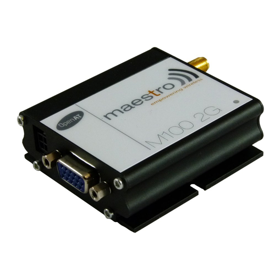
Boasting the reliability the M100 Series is known for, the M100 2G modems are the perfect devices to use in any of your projects facing tough conditions or extended lifetime requirements. Fitted with a standard fifteen pins RS232 port and Windows configuration tool the M100 2G can be set up with minimal effort. - Page 16 Once connected, the interface will switch to the “Modem Status” page, see Figure 4.2.2, displays the reception signal strength (RSSI, refreshed every five seconds), your SIM card network name, as well as the revision number for the embedded application and firmware. Confidential, the whole document is the sole property of Maestro Wireless Solutions ltd.
- Page 17 – IP Ping, – Command String scripting language, The last and not least page of the Maestro Configuration Software is the Terminal, which is a Windows HyperTerminal replacement with log, quick command features, see Figure 4.2.3. Figure 4.2.3: Terminal page - Maestro Configuration Software...
- Page 18 Confidential, the whole document is the sole property of Maestro Wireless Solutions ltd.
-
Page 19: Equipments Description
Connect an antenna with SMA male connector on the modem, make sure the antenna is tightly secured. Take good care of choosing an antenna with the right GSM frequency and an impedance of 50 ; incorrect antenna will affect communication and even damage the modem. Confidential, the whole document is the sole property of Maestro Wireless Solutions ltd. -
Page 20: 15-Pin D-Sub Female Connector (Rs232/Audio)
It is recommended that CTS and DTR pins should never be short-circuited. If the application requires to use "flow- control spoofing" cables, make sure that they do not connect CTS to DTR. Confidential, the whole document is the sole property of Maestro Wireless Solutions ltd. -
Page 21: 4-Pin Micro-Fit Molex Connector (Power And Input/Output)
– Direct connection with standard 9-pin RS-232 port (DTE) – Direct connection with common handset of telephone for voice call – Shielded cable – Cable length 1.1m (w/ connector) Confidential, the whole document is the sole property of Maestro Wireless Solutions ltd. - Page 22 – Polarization Linear Power cord with fuse - ACC-CA10 – 4-pin Microfit connector – 1m AWG20 cables with stripped wire end – 2.5A glass fuse with plastic holder Confidential, the whole document is the sole property of Maestro Wireless Solutions ltd.
- Page 23 DIN rail mount - ACC-DIN – SPCC steel – Thickness: 1.2mm DB15 to DB9 adapter - OTH-004 – Plastic molded with screws – Length: 36mm (w/ connector) Confidential, the whole document is the sole property of Maestro Wireless Solutions ltd.
- Page 24 Confidential, the whole document is the sole property of Maestro Wireless Solutions ltd.
-
Page 25: Default Firmware Settings
6.2 General Purpose Input/Output port /!\ Important notice: The following commands are from Generic AT command guide and will work only if the Maestro SmartPack is disabled (AT+SPMODE=1). Else please refer to the SmartPack user manual to control GPIOs through SmartPack AT commands. - Page 26 – To setup this port as an output, type AT+WIOM=1,"GPIO1",1 on the serial port. Then set the state of the output with AT+WIOW="GPIO1",0 for 0V, or AT+WIOW="GPIO1",1 for 2.8V. Confidential, the whole document is the sole property of Maestro Wireless Solutions ltd.
-
Page 27: Analog Input Port
/!\ Important notice: This section concern only OpenAT developer that will need to control ADC from their application, else the Maestro SmartPack will control analog input through SmartPack AT commands. This port can be used either as a voltage input (0-5V range) or as a current input (0-20mA range). - Page 28 Confidential, the whole document is the sole property of Maestro Wireless Solutions ltd.
-
Page 29: Troubleshooting
7.4 No voice could be heard for the modem’s speaker output when a call is answered – Make sure a voice call has been made (refer to AT command guide) – Enter the AR+SPEAKER=1 command Confidential, the whole document is the sole property of Maestro Wireless Solutions ltd. -
Page 30: Debug, Or Further Command Using Smart Terminal As Example
7.5 Debug, or further command using Smart Terminal as example First, you can find our Hyper Terminal substitute at the following address: http://www.maestro-wireless.com/ smart-terminal Then follow the steps: – Open the software, you can find the shortcut on your desktop, or access it by the Start menu > All Programs >... -
Page 31: Basic Operations
+CME ERROR: 16 Incorrect PIN code (with +CME=1 mode) +CME ERROR: 3 PIN already entered (with +CME=1 mode) Saves parameters in non-volatile AT&W The configuration settings are stored memory Confidential, the whole document is the sole property of Maestro Wireless Solutions ltd.