
Related Manuals for Yamaha F8A


Summary of Contents for Yamaha F8A
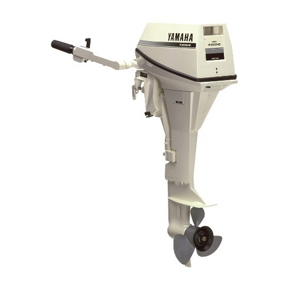
- Page 1 F9.9A OWNER’S MANUAL Read this manual carefully before operating this outboard motor.
- Page 2 Read this manual carefully before operating this outboard motor. Keep this manual onboard in a waterproof bag when boating. This manual should stay with the outboard motor if it is sold.
-
Page 3: Important Manual Information
Therefore some items may not apply to every model. TIP: A TIP provides key information to make pro- cedures easier or clearer. F8A, F9.9A OWNER’S MANUAL Outboards continually seeks advancements in ©2010 by Outboards Group CV 1st Edition, February 2015 product design and quality. -
Page 4: Table Of Contents
Table of contents Safety information......1 Propeller selection ......13 Outboard motor safety ....1 Start-in-gear protection ....Engine oil requirements ....Propeller ..........1 Rotating parts ........Fuel requirements ......Hot parts..........1 Gasoline ........... Electric shock ........1 Muddy or acidic water .... - Page 5 Table of contents Instruments and indicators .... Procedure........Trimming outboard motor..... Indicators........27 Adjusting trim angle for manual tilt Low oil pressure-alert indicator ..models .......... Engine control system....28 Adjusting trim angle (power tilt Alert system ........28 models) ......... Low oil pressure alert .......
- Page 6 Table of contents Removing propeller ......71 Installing propeller ......71 Changing gear oil ......Cleaning fuel tank......73 Inspecting and replacing anode(s) ... 74 Checking battery (for electric start models) ......... 75 Connecting the battery ..... 75 Disconnecting the battery....76 Trouble Recovery ......
-
Page 7: Safety Information
Safety information Outboard motor safety Power tilt Body parts can be crushed between the mo- Observe these precautions at all times. tor and the clamp bracket when the motor is Propeller trimmed or tilted. Keep body parts out of this People can be injured or killed if they come in area at all times. -
Page 8: Gasoline Exposure And Spills
Safety information PFDs, and everyone should wear PFDs when Gasoline exposure and spills there are potentially hazardous boating condi- Take care not to spill gasoline. If gasoline tions. spills, wipe it up immediately with dry rags. People in the water Dispose of rags properly. -
Page 9: Avoid Collisions
Safety information Avoid collisions Passenger training Scan constantly for people, objects, and other Make sure at least one other passenger is boats. Be alert for conditions that limit your trained to operate the boat in the event of an visibility or block your vision of others. emergency. -
Page 10: General Information
General information Identification numbers record Outboard motor serial number The outboard motor serial number is stamped on the label attached to the port side of the clamp bracket. Record your outboard motor serial number in the spaces provided to assist you in ordering spare parts from your Outboards dealer or for reference in case your outboard motor is sto- len. -
Page 11: Ce Marking
General information Product code of model (Approved model code) Code of conformed directives CE Marking Outboard motors affixed with this “CE”mark- ing conform with the directives of; 98/37/EC, 94/25/EC - 2003/44/EC and 2004/108/EC. 1. CE marking location 1. CE marking location... -
Page 12: Read Manuals And Labels
General information Read manuals and labels Before operating or working on this outboard motor: Read this manual. Read any manuals supplied with the boat. Read all labels on the outboard motor and the boat. If you need any additional information, contact your Outboards dealer. Warning labels If these labels are damaged or missing, contact your Outboards dealer for replacements. - Page 13 General information FPP8AER, FPP9.9AER, FPW8AER, FPW9.9AER...
- Page 14 General information Contents of labels The above warning labels mean as follows. WARNING Read Owner’s Manuals and labels. Wear an approved personal flotation de- WARNING vice (PFD). Emergency starting does not have start- Attach engine shut-off cord (lanyard) to ...
- Page 15 General information Electrical hazard Symbols The following symbols mean as follows. Notice/Warning Remote control lever/gear shift lever operat- ing direction, dual direction Read Owner’s Manual Engine start/ Engine cranking Hazard caused by continuous rotation...
-
Page 16: Specifications And Requirements
Specifications and requirements Transom height S: Specifications FPP(8/9.9)AER 430 mm (16.9 in) TIP: FPP(8/9.9)AMH 435 mm (17.1 in) “(AL)” stated in the specification data below Transom height L: represents the numerical value for the alumi- FPP(8/9.9)AER 557 mm (21.9 in) num propeller installed. - Page 17 Specifications and requirements Spark plug (NGK): Gear ratio: BR6HS-10 FPP(8/9.9)AER 2.08(27/13) Spark plug gap: FPP(8/9.9)AMH 2.08(27/13) 0.9–1.0 mm (0.035–0.039 in) FPW(8/9.9)AER 2.92(38/13) Control system: FPW(8/9.9)AMH 2.92(38/13) FPP(8/9.9)AER Remote control FPP(8/9.9)AMH Tiller handle Trim and tilt system: FPW(8/9.9)AER Remote control FPP(8/9.9)AER Manual tilt FPW(8/9.9)AMH Tiller handle FPP(8/9.9)AMH Manual tilt FPW(8/9.9)AER Manual tilt...
-
Page 18: Installation Requirements
Specifications and requirements Gear oil quantity: Installation requirements FPP(8/9.9)AER 0.150 L (0.159 US qt, 0.132 Imp.qt) Boat horsepower rating FPP(8/9.9)AMH 0.150 L (0.159 US qt, WARNING 0.132 Imp.qt) FPW(8/9.9)AER 0.370 L (0.391 US qt, Overpowering a boat can cause severe in- 0.326 Imp.qt) stability. -
Page 19: Battery Requirements
Specifications and requirements The remote control unit must be equipped Your Outboards dealer can help you select the with a start-in-gear protection device(s). This right propeller for your boating needs. Select device prevents the engine from starting un- a propeller that will allow the engine to reach less it is in neutral. -
Page 20: Start-In-Gear Protection
Specifications and requirements Start-in-gear protection Outboards outboard motors affixed with the pic- tured label or Outboards-approved remote con- trol units are equipped with start-in-gear protection device(s). This feature permits the engine to be started only when it is in neutral. Always select neutral before starting the en- gine. -
Page 21: Anti-Fouling Paint
Specifications and requirements tor in muddy or acidic water conditions. However, depending on the model it might not be required. Anti-fouling paint A clean hull improves boat performance. The boat bottom should be kept as clean of marine growth as possible. If necessary, the boat bot- tom can be coated with an anti-fouling paint approved for your area to inhibit marine growth. -
Page 22: Components
Components Components diagram TIP: * May not be exactly as shown; also may not be included as standard equipment on all models (order from dealer). FPP8A; FPP9.9A 1. Top cowling 16.Tiller handle* 2. Cowling lock lever 17.Throttle grip* 3. Anti-cavitation plate 18.Throttle friction adjuster* 4. -
Page 23: Fuel Tank
Components FPP8A; FPP9.9A 1. Top cowling 22.Tilt support knob* 2. Cowling lock lever 23.Remote control box (side mount type)* 3. Anti-cavitation plate 24.Fuel tank 4. Propeller Fuel tank 5. Cooling water inlet 6. Drain screw If your model was equipped with a portable 7. -
Page 24: Fuel Joint
Components 1. Power tilt switch 1. Air vent screw 2. Remote control lever 2. Fuel gauge 3. Neutral interlock trigger 3. Fuel joint 4. Neutral throttle lever 4. Fuel tank cap 5. Main switch / choke switch Fuel joint 6. Engine shut-off switch 7. -
Page 25: Neutral Interlock Trigger
Components Neutral interlock trigger Choke switch To shift out of neutral, first pull the neutral in- To activate the choke system, press in the main switch while the key is turned to the “ ” terlock trigger up. (on) or “ ”... -
Page 26: Throttle Grip
Components Throttle indicator The fuel consumption curve on the throttle in- dicator shows the relative amount of fuel con- sumed for each throttle position. Choose the setting that offers the best performance and fuel economy for the desired operation. 1. Forward “ ”... -
Page 27: Engine Shut-Off Cord (Lanyard) And Clip
Components the loss of most steering control. Also, without engine power, the boat could slow rapidly. This could cause people and ob- jects in the boat to be thrown forward. 1. Cord 2. Clip 3. Engine shut-off switch When constant speed is desired, tighten the adjuster to maintain the desired throttle set- ting. -
Page 28: Engine Stop Button
Components 2. Clip Manual starter handle 3. Engine shut-off switch The manual starter handle is used to crank and start the engine. Engine stop button The engine stop button stops the engine when the button is pushed. Main switch The main switch controls the ignition system; its operation is described below. -
Page 29: Power Tilt Switch
Components Power tilt switch The power tilt system adjusts the outboard motor angle in relation to the transom. Push- ing the switch “ ” (up) tilts the outboard mo- tor up. Pressing the switch “ ” (down) tilts the outboard motor down. When the switch is released, the outboard motor will stop in its current position. -
Page 30: Trim Rod (Tilt Pin)
Components Trim rod (tilt pin) The position of the trim rod determines the minimum trim angle of the outboard motor in relation to the transom. NOTICE Do not use the tilt support lever or knob when trailering the boat. The outboard mo- tor could shake loose from the tilt support and fall. -
Page 31: Power Tilt Unit
Components mal running position, use an additional support device to secure it in the tilt posi- tion. Power tilt unit This unit tilts the outboard motor up and down and is controlled with the power tilt switch. NOTICE Do not step on or exert pressure on the power tilt motor. - Page 32 Components 1. Low oil pressure-alert indicator...
-
Page 33: Instruments And Indicators
Instruments and indicators Indicators Low oil pressure-alert indicator If oil pressure drops too low, this indicator will light up. For further information, see page 28. NOTICE Do not continue to run the engine if the low oil pressure-alert indicator is on and the engine oil level is lower. -
Page 34: Engine Control System
Engine control system Alert system NOTICE Do not continue to operate the engine if a alert device has activated. Consult your Outboards dealer if the problem cannot be lo- cated and corrected. Low oil pressure alert If the oil pressure drops too low, the alert de- vice will activate. -
Page 35: Installation
Installation Installation The information presented in this section is in- tended as reference only. It is not possible to provide complete instructions for every possi- ble boat and motor combination. Proper mounting depends in part on experience and the specific boat and motor combination. WARNING Overpowering a boat could cause se- ... - Page 36 Installation speed will rise abnormally and cause the en- gine to overheat. If the mounting height is too low, the water resistance will increase and thereby reduce engine efficiency. Mount the outboard motor so that the anti-cavitation plate is between the bottom of the boat and a level 25 mm (1 in) below it.
-
Page 37: Clamping The Outboard Motor
Installation runs at different heights can help determine the boat. Otherwise the engine could be the optimum mounting height. Consult your completely lost if it accidentally falls off Outboards dealer or boat manufacturer for the transom. further information on determining the prop- er mounting height. -
Page 38: Operation
Operation 1. For the first hour of operation: First-time operation Run the engine at varying speeds up to 2000 r/min or approximately half throttle. Fill engine oil 2. For the second hour of operation: The engine is shipped from the factory without Increase engine speed as much as nec- engine oil. -
Page 39: Remove The Top Cowling
Operation an emergency reserve. With the boat level on Controls a trailer or in the water, check the fuel level. Tiller handle models: For fuel filling instructions, see page 36. Move the tiller handle fully to the left and Remove the top cowling right to make sure operation is smooth. -
Page 40: Engine Oil
Operation Check the oil level using the dipstick to be sure the level falls between the upper and lower marks. Fill with oil if it is below the lower mark, or drain to the specified level if it is above the upper mark. 1. -
Page 41: Install Top Cowling
Operation nected, cooling water can leak out and the After installing, check the fitting of the top engine can overheat during operation. cowling by pushing it with both hands. If the top cowling is loose, have it repaired by your Outboards dealer. -
Page 42: Battery
Operation Operate each of the power tilt switches to check that all switches work. Tilt the outboard motor up and check that the tilt rod is pushed out completely. Check that the tilt rod is free of corrosion or other flaws. Tilt the outboard motor down. -
Page 43: Operating Engine
Operation Sending fuel (portable tank) If there is an air vent screw on the fuel tank cap, loosen it 2 or 3 turns. Tighten the filler cap securely. 10. Wipe up any spilled gasoline immediately with dry rags. Dispose rags properly ac- cording to local laws or regulations. -
Page 44: Starting Engine
Operation Avoid accidentally pulling the cord dur- TIP: ing normal operation. Loss of engine Wipe up any spilled gasoline immediately with power means the loss of most steering dry rags. Dispose rags properly according to control. Also, without engine power, the local laws or regulations. - Page 45 Operation Pull the manual starter handle slowly until you feel resistance. Then give a strong pull straight out to crank and start the en- gine. Place the throttle grip in the “ ” (start) position. After the engine starts, slowly return the manual starter handle to its original posi- tion before releasing it.
- Page 46 Operation TIP: If the choke knob is left in the “ ” (start) position while the engine is running, the en- gine will run poorly or stall. When the engine is cold, for example, when the ambient temperature is low in winter, it needs to be warmed up.
- Page 47 Operation After the engine starts, slowly return the manual starter handle to its original posi- tion before releasing it. Slowly return the throttle grip to the fully closed position. Pull the manual starter handle slowly until you feel resistance. Then give a strong pull straight out to crank and start the en- gine.
- Page 48 Operation Open the throttle slightly without shifting using the neutral throttle lever. TIP: The start-in-gear protection device prevents TIP: the engine from starting except when in neu- tral. The neutral throttle lever can only be used Attach the engine shut-off cord to a se- when the remote control lever is in neutral.
-
Page 49: Checks After Starting Engine
Operation pump is pumping water through the cooling water passages. If the cooling water passag- es are frozen, it may take a while for water to start flowing out of the pilot hole. NOTICE If water is not flowing out of the pilot hole at all times while the engine is running, overheating and serious damage could occur. -
Page 50: Checks After Engine Warm Up
Operation Checks after engine warm up Shifting While the boat is tightly moored, and without applying throttle, confirm that the engine shifts smoothly into forward and reverse, and back to neutral. Stop switches Turn the main switch to “ ”, or press the ... - Page 51 Operation After the engine is at idle speed in gear move the remote control lever / gear shift lever firmly and crisply into the neutral po- sition. To shift from in gear (forward/reverse) to neu- tral Close the throttle so that the engine slows to idle speed.
-
Page 52: Stopping Boat
Operation Stopping boat WARNING Do not use the reverse function to slow down or stop the boat as it could cause you to lose control, be ejected, or impact the steering wheel or other parts of the boat. This could increase the risk of se- rious injury. -
Page 53: Procedure
Operation Trimming outboard motor WARNING Excessive trim for the operating condi- tions (either trim up or trim down) can cause boat instability and can make steer- ing the boat more difficult. This increases the possibility of an accident. If the boat begins to feel unstable or is hard to steer, slow down and/or readjust the trim angle. -
Page 54: Adjusting Trim Angle (Power Tilt Models)
Operation Adjusting trim angle (power tilt mod- els) WARNING Be sure all people are clear of the out- board motor when adjusting the trim an- gle. Body parts can be crushed between the motor and the clamp bracket when the motor is trimmed or tilted. -
Page 55: Adjusting Boat Trim
Operation Make test runs with the trim set to different an- gles to find the position that works best for your boat and operating conditions. Adjusting boat trim When the boat is on plane, a bow-up attitude results in less drag, greater stability and effi- ciency. -
Page 56: Procedure For Tilting Up (Manual Tilt Models)
Operation WARNING Make sure that no one is near the outboard motor when tilting the outboard motor up or down. Otherwise, body parts could be crushed between the outboard motor and the clamp bracket. WARNING Leaking fuel is a fire hazard. If there is a fuel joint on the outboard motor, discon- nect the fuel line or close the fuel cock if the engine will be tilted for more than a few... -
Page 57: Procedure For Tilting Up (Power Tilt Models)
Operation 2. Press the power tilt switch “ ” (up) until 4. Pull up the shallow water lever (if equipped). the outboard motor has tilted up com- Hold the rear of the top cowling with one pletely. hand and tilt the engine up fully. Push the tilt support knob into the clamp bracket. -
Page 58: Procedure For Tilting Down (Manual Tilt Models)
Operation Procedure for tilting down (power tilt models) Push the power tilt switch “ ” (up) until the outboard motor is supported by the tilt rod and the tilt support knob becomes free. Pull out the tilt support knob. Models equipped with trim rods: Once the outboard motor is supported with the tilt support lever, press the power tilt switch “... - Page 59 Operation water cruising system is being used. Hit- ting an underwater obstacle could cause the outboard motor to lift out of the water, resulting in loss of control. Use extra care when operating in re- verse. Too much reverse thrust can cause the outboard motor to lift out of the water, increasing the chance of acci- dent and personal injury.
-
Page 60: Power Tilt Models
Operation Procedure for power tilt models Place the remote control lever in neutral. To return the outboard motor to the nor- mal running position, place the remote control lever / gear shift lever in neutral. 2. Slightly tilt the outboard motor up to the Place the tilt lock lever in the lock/down desired position using the power tilt position, then slightly tilt the outboard mo-... -
Page 61: Cruising In Other Conditions
Operation Cruising in other conditions Cruising in salt water After operating in salt water, flush the cooling water passages with fresh water to prevent them from becoming clogged. Also rinse the outside of the outboard motor with fresh wa- ter. Cruising in muddy, turbid, or acidic water Outboards strongly recommends that you use the optional chromium-plated water pump kit... -
Page 62: Maintenance
Maintenance Disconnect the fuel line from the outboard Transporting and storing out- motor. board motor Tighten the fuel tank cap and its air vent screw. WARNING When the outboard motor is tilted pro- USE CARE when transporting fuel tank, ... - Page 63 Maintenance To prevent steering movement, turn the adjuster lever to “A” (if equipped with the adjuster lever). To hold the steering bracket easily, raise the tiller handle to the vertical position (if equipped with the tiller handle). 1. Steering bracket 2.
-
Page 64: Storing Outboard Motor
Maintenance the attitude shown when transporting and storing it. If storing or transporting the outboard motor on its side (not up- right), put it on a cushion after draining the engine oil. Do not place the outboard motor on its ... -
Page 65: Lubrication
Maintenance 12. If the “Fogging Oil” is not available, run plate, or if the water supply is insuffi- cient, engine seizure may occur. the engine at a fast idle until the fuel sys- tem becomes empty and the engine stops. 13. -
Page 66: Cleaning The Outboard Motor
Maintenance After shutting off the engine, unscrew the operation. Water will leak out of the garden hose connector from the fitting on connector instead of cooling the en- the bottom cowling. gine, which can cause serious over- heating. Be sure the connector is tightened securely on the fitting after flushing the engine. -
Page 67: Periodic Maintenance
Maintenance Periodic maintenance Severe operating conditions Severe operating conditions involve one or WARNING more of the following types of operation on a regular basis: These procedures require mechanical Operating continuously at or near maxi- skills, tools, and supplies. If you do not ... -
Page 68: Maintenance Chart 1
Maintenance Maintenance chart 1 TIP: Refer to the sections in this chapter for explanations of each owner-specific action. The maintenance cycle on these charts assume usage of 100 hours per year and regular flushing of the cooling water passages. Maintenance frequency should be adjusted when op- erating the engine under adverse conditions such as extended trolling. - Page 69 Maintenance Initial Every Item Actions 20 hours 100 hours 300 hours 500 hours (3 months) (1 year) (3 years) (5 years) Fuel line (High pres- Inspection sure) Fuel line (High pres- Inspection or replace- sure) ment as necessary Fuel line (Low pres- Inspection sure) Fuel line (Low pres-...
-
Page 70: Maintenance Chart 2
Maintenance Initial Every Item Actions 20 hours 100 hours 300 hours 500 hours (3 months) (1 year) (3 years) (5 years) Wire harness connec- Inspection or replace- tions/wire coupler con- ment as necessary nections Fuel tank (Outboards por- Inspection and clean- table tank) ing as necessary Maintenance chart 2... -
Page 71: Greasing
Maintenance Greasing Outboards grease A (water resistant grease) Outboards grease D (corrosion resistant grease; for propeller shaft) FPP8A; FPP9.9A... - Page 72 Maintenance FPW8A; FPW9.9A...
-
Page 73: Cleaning And Adjusting Spark Plug
Maintenance Cleaning and adjusting spark plug The spark plug is an important engine compo- nent and is easy to inspect. The condition of the spark plug can indicate something about the condition of the engine. For example, if the center electrode porcelain is very white, this could indicate an intake air leak or carburetion problem in that cylinder. -
Page 74: Inspecting Idle Speed
Maintenance Changing engine oil NOTICE Change the engine oil after the first 20 hours of operation or 3 months, and every 100 hours or at 1-year intervals thereafter. Otherwise the engine will wear quickly. Extract the engine oil with an oil changer. sition (not tilted). - Page 75 Maintenance 1. Oil filler cap 1. Oil changer TIP: Recommended engine oil: 4-stroke outboard motor oil If the oil changer is not available, remove the Engine oil quantity: drain screw while holding a container under 0.8 L (0.85 US qt, 0.70 Imp.qt) the drain hole.
-
Page 76: Inspecting Wiring And Connectors
Maintenance 11. Start the engine and make sure that the ing, or installing the propeller, place the low oil pressure-alert indicator remains shift control in neutral, turn the main switch to “ ” (off) and remove the key, off. Also, make sure that there are no oil leaks. -
Page 77: Removing Propeller
Maintenance Check the propeller shaft oil seal for dam- 6. Thrust washer age. 3. Remove propeller, washer (if equipped), and thrust washer. Removing propeller Installing propeller Spline models Straighten the cotter pin and pull it out us- Spline models ing a pair of pliers. -
Page 78: Changing Gear Oil
Maintenance NOTICE: Do not reuse the cotter pin. netic gear oil drain screw, this can in- Otherwise, the propeller can come off dicate lower unit problem. Consult during operation. your Outboards dealer. 1. Gear oil drain screw TIP: 2. Oil level plug If the propeller nut does not align with the pro- TIP: peller shaft hole after tightening to the speci-... -
Page 79: Cleaning Fuel Tank
Maintenance Recommended gear oil: Cleaning fuel tank Hypoid gear oil SAE#90 Gear oil quantity: WARNING FPP(8/9.9)AER 0.150 L (0.159 US qt, Gasoline is highly flammable, and its va- 0.132 Imp.qt) pors are flammable and explosive. FPP(8/9.9)AMH 0.150 L (0.159 US qt, 0.132 Imp.qt) If you have any question about properly ... -
Page 80: Inspecting And Replacing Anode(S)
Maintenance Inspecting and replacing anode(s) Outboards outboard motors are protected from corrosion by sacrificial anodes. Inspect the external anodes periodically. Remove scales from the surfaces of the anodes. Consult a Outboards dealer for replacement of external anodes. NOTICE Do not paint anodes, as this would render them ineffective. -
Page 81: Checking Battery (For Electric Start Models)
Maintenance 2. Check the battery’s charge. If your boat is TIP: equipped with the digital speedometer, Inspect ground leads attached to external an- the voltmeter and low battery alert func- odes on equipped models. Consult a Outboards tions will help you monitor the battery’s dealer for inspection and replacement of inter- charge. -
Page 82: Disconnecting The Battery
Maintenance 1. Red cable 2. Black cable 3. Battery The electrical contacts of the battery and cables must be clean and properly con- nected, or the battery will not start the en- gine. Disconnecting the battery Turn off the battery cut-off switch (if equipped) and main switch. -
Page 83: Trouble Recovery
Trouble Recovery Q. Is fuel filter clogged? Troubleshooting A. Clean or replace filter. A problem in the fuel, compression, or ignition systems can cause poor starting, loss of pow- Q. Is starting procedure incorrect? er, or other problems. This section describes A. - Page 84 Trouble Recovery A. Check for pinched or kinked fuel line or oth- A. Return to home position. er obstructions in fuel system. Q. Is motor angle too high? Q. Is fuel contaminated or stale? A. Return to normal operating position. A.
- Page 85 Trouble Recovery Q. Is load on boat improperly distributed? A. Remove foreign matter and clean lower A. Distribute load to place boat on an even unit. plane. Q. Is fuel system obstructed? Q. Is water pump or thermostat faulty? A. Check for pinched or kinked fuel line or oth- A.
-
Page 86: Temporary Action In Emergency
Trouble Recovery A. Connect correctly. If the outboard motor hits an object in the wa- ter, follow the procedure below. Q. Is heat range of spark plug incorrect? A. Inspect spark plug and replace it with rec- ommended type. Q. Is high pressure fuel pump drive belt bro- ken? A. -
Page 87: Power Tilt Will Not Operate
Trouble Recovery WARNING Use this procedure only in an emergen- cy to return to the nearest port for re- pairs. When the emergency starter rope is used to start the engine, the start-in- gear protection device does not operate. Make sure the remote control lever is in neutral. -
Page 88: Emergency Starting Engine
Trouble Recovery Do not touch the ignition coil, spark plug wire, spark plug cap, or other electrical components when starting or operating the motor. You could get an electrical shock. Emergency starting engine Remove the top cowling. Remove the start-in-gear protection ca- ble from the starter, if equipped. -
Page 89: Engine Fails To Operate
Trouble Recovery ly. NOTICE: Do not attempt to run the out- board motor until it has been completely inspected. Engine fails to operate Emergency engine operation If the battery voltage is low or in the unlikely event of an ignition system malfunction, the engine speed may become erratic or the en- gine may stop. - Page 90 OUTBOARDS GROUP CV Printed in China...