Table of Contents
Advertisement
Advertisement
Table of Contents

Related Manuals for Asus Z170-E


Summary of Contents for Asus Z170-E
- Page 1 Z170-E...
- Page 2 Product warranty or service will not be extended if: (1) the product is repaired, modified or altered, unless such repair, modification of alteration is authorized in writing by ASUS; or (2) the serial number of the product is defaced or missing.
-
Page 3: Table Of Contents
Contents Safety information ....................... v About this guide ......................v Package contents ...................... vii Z170-E specifications summary................vii Chapter 1: Product Introduction Before you proceed ................... 1-1 Motherboard overview ................1-1 Central Processing Unit (CPU) ..............1-5 System memory ..................1-9 Expansion slots .................. - Page 4 Monitor menu ................... 2-46 Boot menu ....................2-51 Tool menu ....................2-57 2.9.1 ASUS EZ Flash 3 Utility ............2-57 2.9.2 Secure Erase ................2-57 2.9.3 ASUS O.C. Profile ..............2-59 2.9.4 ASUS DRAM SPD Information ..........2-60 2.9.5 Graphics Card Information ............2-60 2.10...
-
Page 5: Safety Information
Safety information Electrical safety • To prevent electrical shock hazard, disconnect the power cable from the electrical outlet before relocating the system. • When adding or removing devices to or from the system, ensure that the power cables for the devices are unplugged before the signal cables are connected. If possible, disconnect all power cables from the existing system before you add a device. -
Page 6: Conventions Used In This Guide
Refer to the following sources for additional information and for product and software updates. ASUS websites The ASUS website provides updated information on ASUS hardware and software products. Refer to the ASUS contact information. Optional documentation Your product package may include optional documentation, such as warranty flyers, that may have been added by your dealer. -
Page 7: Package Contents
Check your motherboard package for the following items: ASUS Z170-E Motherboard Motherboard 2 x Serial ATA 6.0 Gb/s cables Cables 1 x ASUS SLI bridge connector 1 x M.2 screw package Accessories 1 x CPU installation tool Support DVD Application DVD... - Page 8 - 6 x USB 3.0/2.0 ports (4 ports at mid-board, 2 ports at back panel, blue) - 6 x USB 2.0/1.1 ports (4 ports at mid-board, 2 ports at back panel) ASMedia USB 3.1 controllers- supports ASUS USB 3.1 Boost and 3A power ® output - 1 x USB 3.1/3.0/2.0 port at back panel (Type-C)
- Page 9 Z170-E specifications summary Superb Performance OC Design - ASUS PRO Clock Technology - Full BCLK range for extreme overclocking performance 5-Way Optimization - Whole system optimization with a single click! Perfectly consolidates better CPU performance, power saving, digital power control, system cooling and app...
- Page 10 - ASUS Overvoltage Protection - World-class circuit-protecting power design - ASUS DIGI+ VRM - 4 Phase digital power design - ASUS DRAM Overcurrent Protection - Prevents damage from short circuits - ASUS Stainless-Steel Back I/O - 3x corrosion-resistance for greater durability...
- Page 11 ASUS Quiet - ASUS Fan Xpert 3 Thermal Solution - ASUS Fanless Design: Heat-sink solution Precision Tweaker 2: - CPU Core/Cache Voltage: Adjustable CPU Core/Cache Voltage at 0.005V increment - CPU Graphics Voltage: Adjustable CPU Graphics voltage at 0.005V increment - CPU VCCIO Voltage: Adjustable CPU VCCIO Voltage at 0.0125V increment...
- Page 12 1 x 5-pin EXT_FAN (Extension Fan) connector 128 Mb Flash ROM, UEFI AMI BIOS, PnP, DMI3.0, WfM2.0, SM BIOS 3.0, ACPI 5.0, Multi-language BIOS, ASUS EZ Flash 3, CrashFree BIOS 3, F11 EZ BIOS Features Tuning Wizard, F6 Qfan Control, F3 My Favorites, Quick Note, Last Modified...
-
Page 13: Chapter 1: Product Introduction
1.2.1 Placement direction When installing the motherboard, place it into the chassis in the correct orientation. The edge with external ports goes to the rear part of the chassis. ASUS Z170-E Series... -
Page 14: Screw Holes
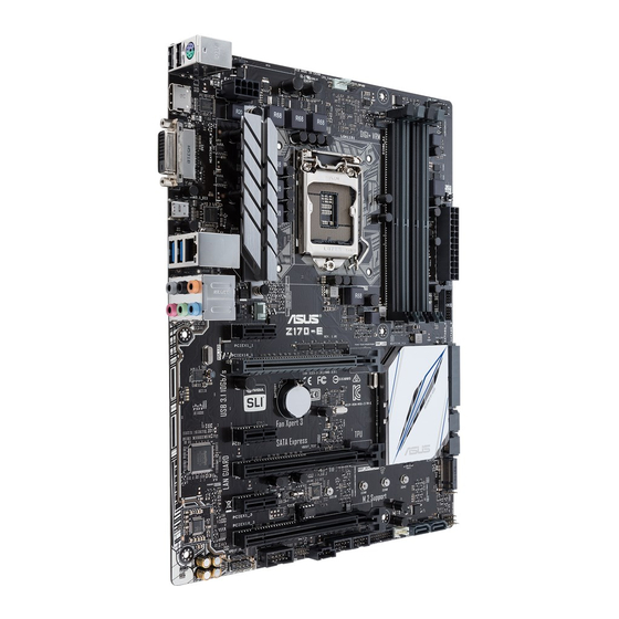
1.2.2 Screw holes Place nine screws into the holes indicated by circles to secure the motherboard to the chassis. Do not overtighten the screws! Doing so can damage the motherboard. Place this side towards the rear of the chassis Chapter 1: Product Introduction... - Page 15 1.2.3 Motherboard layout ASUS Z170-E Series...
-
Page 16: Layout Contents
1.2.4 Layout contents Connectors/Jumpers/Slots/LED Page Intel LGA1151 CPU socket ® CPU, water pump, CPU optional, extension, and chassis fan connectors (4-pin CPU_FAN; 4-pin W_PUMP; 4-pin CPU_OPT; 5-pin EXT_FAN; 4-pin 1-26 CHA_FAN1-2) DDR4 DIMM slots MemOK! button 1-37 ATX power connectors (24-pin EATXPWR, 8-pin EATX12V) 1-27 USB 3.0 connectors (20-1 pin USB3_12, USB3_34) 1-33... -
Page 17: Central Processing Unit (Cpu)
Contact your retailer immediately if the PnP cap is missing, or if you see any damage to the PnP cap/socket contacts/motherboard components. ASUS will shoulder the cost of repair only if the damage is shipment/ transit-related. -
Page 18: Installing The Cpu
1.3.1 Installing the CPU Top of CPU Bottom of CPU Bottom of CPU Chapter 1: Product Introduction... - Page 19 Top of CPU ASUS Z170-E Series...
-
Page 20: Cpu Heatsink And Fan Assembly Installation
1.3.2 CPU heatsink and fan assembly installation Apply the Thermal Interface Material to the CPU heatsink and CPU before you install the heatsink and fan, if necessary. To install the CPU heatsink and fan assembly Chapter 1: Product Introduction... -
Page 21: System Memory
The motherboard comes with four Double Data Rate 4 (DDR4) Dual Inline Memory Modules (DIMM) slots. A DDR4 module is notched differently from a DDR, DDR2, or DDR3 module. DO NOT install a DDR, DDR2, or DDR3 memory module to the DDR4 slot. ASUS Z170-E Series... -
Page 22: Recommended Memory Configurations
2.5 Ai Tweaker menu for manual memory frequency adjustment. • For system stability, use a more efficient memory cooling system to support a full memory load (4 DIMMs). • Visit the ASUS website at: www.asus.com for the latest QVL. 1-10 Chapter 1: Product Introduction... - Page 23 Z170-E Motherboard Qualified Vendors Lists (QVL) DDR4 3466 (O.C.) MHz capability Vendors Part No. Size Chip Chip NO. Timing Voltage DIMM socket Brand support (Optional) G.SKILL F4-3466C16D-8GRK 8GB(4GB*2) Samsung K4A4G085WD 16-18-18-38 1.35V • G.SKILL F4-3466C16D-8GTZ 8GB(4GB*2) Samsung K4A4G085WD 16-18-18-38 1.35V •...
- Page 24 DDR4 3000 (O.C.) MHz capability Vendors Part No. Size Chip Chip NO. Timing Voltage DIMM socket Brand support (Optional) G.SKILL F4-3000C15Q-16GRR 16GB(4GB*4) Samsung K4A4G085WD 15-15-15-35 1.35V • • G.SKILL F4-3000C15Q-16GRB 16GB(4GB*4) Samsung K4A4G085WD 15-15-15-35 1.35V • • G.SKILL F4-3000C15Q-16GRK 16GB(4GB*4) Samsung K4A4G085WD 15-15-15-35...
- Page 25 • • KLEVV IMA451U6MFR8N-CF0 (XMP) ISDT I5AN4G8NMFR 15-15-15-35 • • • Team TCD44G2666C15ABK (XMP) Samsung K4A4G085WD 15-15-15-35 • • • Team TCD48G2666C15ABK (XMP) 32GB Team TCD48G2666C15ABK 15-15-15-35 • • • (8GB*4) (continued on the next page) ASUS Z170-E Series 1-13...
- Page 26 DDR4 2400 (O.C.) MHz capability Vendors Part No. Size Chip Chip NO. Timing Voltage DIMM Brand socket support (Optional) AVEXIR AVD4U24001604G-4CIR(XMP) 16-16-16-36 • • • AVEXIR AVD4U24001608G-4M 32GB SK Hynix H5AN4G8NMFRTFC 16-16-16-39 • • • (4GB*8) AVEXIR AVD4U24001608G-4M(XMP) 32GB SK Hynix H5AN4G8NMFRTFC 16-16-16-36 •...
- Page 27 • • Transcend TS1GLH64V1H Samsung K4A4G085WD 15-15-15-37 • • • Transcend TS512MLH64V1H Samsung K4A4G085WD 15-15-15-37 • • • UMAX 84G44G93MC- Micron D9RGQ 15-15-15-36 • • • 21OMCALGF15 UMAX 84G48G93MC- Micron D9RGQ 15-15-15-36 • • • 21OMCGNGF15 ASUS Z170-E Series 1-15...
-
Page 28: Dimm Installation
1.4.3 DIMM installation To remove a DIMM 1-16 Chapter 1: Product Introduction... -
Page 29: Expansion Slots
After installing the expansion card, configure it by adjusting the software settings: Turn on the system and change the necessary BIOS settings, if any. See Chapter 2 for information on BIOS setup. Install the software drivers for the expansion card. ASUS Z170-E Series 1-17... - Page 30 1.5.3 PCI Express 3.0 / 2.0 x1 slots This motherboard supports PCI Express x1 network cards, SCSI cards, and other cards that comply with the PCI Express specifications. 1.5.4 PCI Express 3.0 / 2.0 x16 slots This motherboard supports PCI Express x16 network cards, SCSI cards, and other cards that comply with the PCI Express specifications.
-
Page 31: Irq Assignments For This Motherboard
Shared – – – ASMedia USB 3.1 Controller Shared – – – Shared – – – SATA6G_3 – – Shared – SATA6G_4 – – – Shared SATA6G_5 – – Shared – SATA6G_6 – – – Shared ASUS Z170-E Series 1-19... -
Page 32: Jumpers
Jumpers Clear RTC RAM (2-pin CLRTC) This jumper allows you to clear the Real Time Clock (RTC) RAM in CMOS. You can clear the CMOS memory of date, time, and system setup parameters by erasing the CMOS RTC RAM data. The onboard button cell battery powers the RAM data in CMOS, which include system setup information such as system passwords. - Page 33 CPU. To gain more CPU voltage setting, insert the jumper to pins 2-3. To go back to its default CPU voltage setting, insert the jumper to pins 1-2. ASUS Z170-E Series 1-21...
-
Page 34: Connectors
Connectors 1.7.1 Rear panel connectors Rear panel connectors PS/2 keyboard/mouse port USB 2.0 ports 910 DVI-D port HDMI port USB Type-C port USB 3.0 ports 56 (supports USB 3.1 Boost) (supports USB 3.1 Boost) LAN port* Audio I/O ports** * and **: Refer to the tables on the next page for LAN port LEDs and audio port definitions. 1-22 Chapter 1: Product Introduction... - Page 35 Front Speaker Out Front Speaker Out Pink Mic In Mic In Mic In Mic In Orange – – Center/Subwoofer Center/Subwoofer Gray – – – Side Speaker Out Black – Rear Speaker Out Rear Speaker Out Rear Speaker Out ASUS Z170-E Series 1-23...
-
Page 36: Internal Connectors
1.7.2 Internal connectors Serial port connector (10-1 pin COM) This connector is for a serial (COM) port. Connect the serial port module cable to this connector, then install the module to a slot opening at the back of the system chassis. The COM module is purchased separately. - Page 37 The M.2 socket shares SATA ports with SATA Express. Only one SATA device could be activated. To use an M.2 SATA device, refer to section 2.6.8 Onboard Devices Configuration regarding the BIOS switch. • The SATA EXPRESS connector can support one SATA Express device or two SATA devices. ASUS Z170-E Series 1-25...
- Page 38 The CPU_FAN connector supports the CPU fan of maximum 1A (12W) fan power. • W_PUMP function support depends on water cooling device. • The CPU_FAN connector and CHA_FAN connectors support the ASUS FAN Xpert 3 feature. • The CPU fan connector detects the type of CPU fan installed and automatically switches the control modes.
- Page 39 1000W power or above to ensure the system stability. • If you are uncertain about the minimum power supply requirement for your system, refer to the Recommended Power Supply Wattage Calculator at http://support.asus. com/PowerSupplyCalculator/PSCalculator.aspx?SLanguage=en-us for details. ASUS Z170-E Series 1-27...
- Page 40 DirectKey connector (2-pin DRCT) This connector is for the chassis-mounted button that supports the DirectKey function. Connect the button cable that supports DirectKey, from the chassis to this connector on the motherboard. Ensure that your chassis comes with the extra button cable that supports the DirectKey feature.
- Page 41 This socket supports M Key and type 2242/2260/2280/22110 storage devices. • The M.2 (NGFF) SSD module is purchased separately. • The M.2 shares SATA mode with SATA Express. Change this item before installing M.2 SATA devices. ASUS Z170-E Series 1-29...
- Page 42 TPM connector (14-1 pin TPM) This connector supports a Trusted Platform Module (TPM) system, which securely store keys, digital certificates, passwords and data. A TPM system also helps enhance network security, protects digital identities, and ensures platform integrity. System warning speaker (4 pin SPEAKER) This 4-pin connector is for the chassis-mounted system warning speaker.
- Page 43 Pressing the power switch for more than four seconds while the system is ON turns the system OFF. • Reset button (2-pin RESET) This 2-pin connector is for the chassis-mounted reset button for system reboot without turning off the system power. ASUS Z170-E Series 1-31...
- Page 44 USB 2.0 connectors (10-1 pin USB1112, USB1314) These connectors are for USB 2.0 ports. Connect the USB module cable to any of these connectors, then install the module to a slot opening at the back of the system chassis. These USB connectors comply with USB 2.0 specifications and supports up to 480 Mb/s connection speed.
- Page 45 The plugged USB 3.0 device will run on xHCI mode. • These USB 3.0 ports support native UASP transfer standard in Windows 10 / ® Windows 8.1 / Windows 8 and Turbo Mode when using USB 3.0 Boost feature. ® ® ASUS Z170-E Series 1-33...
- Page 46 Thunderbolt header (5-pin TB_HEADER) This connector is for the add-on Thunderbolt I/O card that supports Intel’s Thunderbolt Technology, allowing you to connect up to six Thunderbolt-enabled devices and a DisplayPort-enabled display in a daisy-chain configuration. The add-on Thunderbolt I/O card and Thunderbolt cables are purchased separately. 1-34 Chapter 1: Product Introduction...
-
Page 47: Onboard Leds
The POST State LEDs provide the status of these key components during POST (Power-On-Self Test): CPU, memory modules, VGA card, and hard disk drives. If an error is found, the critical component’s LED stays lit up until the problem is solved. ASUS Z170-E Series 1-35... - Page 48 Audio LED Lighting These LEDs light up when the system is fully powered and operating. To change the behavior of the LEDs to still mode or breathing mode, refer to BIOS section 2.6.8 Onboard Devices Configuration > Audio LED Lighting for details. 1-36 Chapter 1: Product Introduction...
-
Page 49: Onboard Buttons And Switches
BIOS default settings. A message will appear during POST reminding you that the BIOS has been restored to its default settings. • We recommend that you download and update to the latest BIOS version from www.asus.com after using the MemOK! function. ASUS Z170-E Series 1-37... -
Page 50: Software Support
Place the Support DVD into the optical drive. If Autorun is enabled in your computer, the DVD automatically displays the lists of the unique features of your ASUS motherboard. Click the Drivers, Utilities, AHCI/RAID Driver, Manual, Contact, or Specials tabs to display their respective menus. -
Page 51: Chapter 2: Bios Setup
BIOS Setup Knowing BIOS The new ASUS UEFI BIOS is a Unified Extensible Interface that complies with UEFI architecture, offering a user-friendly interface that goes beyond the traditional keyboard- only BIOS controls to enable a more flexible and convenient mouse input. You can easily navigate the new UEFI BIOS with the same smoothness as your operating system. -
Page 52: Bios Setup Program
BIOS setup program Use the BIOS Setup to update the BIOS or configure its parameters. The BIOS screen include navigation keys and brief onscreen help to guide you in using the BIOS Setup program. Entering BIOS at startup To enter BIOS Setup at startup, press <Delete> during the Power-On Self Test (POST). If you do not press <Delete>, POST continues with its routines. -
Page 53: Ez Mode
Click to go to Advanced mode Loads optimized Search on the FAQ default settings Click to display boot devices Selects the boot device priority The boot device options vary depending on the devices you installed to the system. ASUS Z170-E Series... -
Page 54: Advanced Mode
2.2.2 Advanced Mode The Advanced Mode provides advanced options for experienced end-users to configure the BIOS settings. The figure below shows an example of the Advanced Mode. Refer to the following sections for the detailed configurations. To switch from EZ Mode to Advanced Mode, click Advanced Mode or press <F7> hotkey. Configuration fields Quick Note (F9) Pop-up Menu... -
Page 55: Menu Bar
This button above the menu bar allows you to view and tweak the overclocking settings of your system. It also allows you to change the motherboard’s SATA mode from AHCI to RAID mode. Refer to section 2.2.4 EZ Tuning Wizard for more information. ASUS Z170-E Series... -
Page 56: Hot Keys
Move your mouse over this button to show a QR code, scan this QR code on your mobile device to connect to the BIOS FAQ web page of the ASUS support website. You can also scan the following QR code:... -
Page 57: Qfan Control
Click to activate DC Mode configured PWM Mode Select a profile to apply to Click to apply the fan setting your fans Click to undo the Click to go back to main menu changes Select to manually configure your fans ASUS Z170-E Series... - Page 58 Configuring fans manually Select Manual from the list of profiles to manually configure your fans’ operating speed. Speed points Select to manually configure your fans To configure your fans: Select the fan that you want to configure and to view its current status. Click and drag the speed points to adjust the fans’...
-
Page 59: Ez Tuning Wizard
To start OC Tuning: Press <F11> on your keyboard or click from the BIOS screen to open EZ Tuning Wizard screen. Click OC then click Next. Select a PC scenario Daily Computing or Gaming/Media Editing, then click Next. ASUS Z170-E Series... -
Page 60: Creating Raid
Select a Main Cooling System BOX cooler, Tower cooler, Water cooler, or I’m not sure, then click Next. After selecting the Main Cooling System, click Next then click Yes to start the OC Tuning. Creating RAID To create RAID: Press <F11> on your keyboard or click from the BIOS screen to open EZ Tuning Wizard screen. - Page 61 Speed (RAID5). After selecting the type of RAID, click Next then click Yes to continue the RAID setup. After the RAID setup is done, click Yes to exit the setup then click OK to reset your system. ASUS Z170-E Series 2-11...
-
Page 62: My Favorites
My Favorites My Favorites is your personal space where you can easily save and access your favorite BIOS items. My Favorites comes with several performance, power saving, and fast boot related items by default. You can personalize this screen by adding or removing items. Chapter 2: BIOS Setup 2-12... - Page 63 • Configuration items such as Memory SPD Information, system time and date. Click Exit (ESC) or press <Esc> key to close Setup Tree Map screen. Go to My Favorites menu to view the saved BIOS items. ASUS Z170-E Series 2-13...
-
Page 64: Main Menu
Main menu The Main menu screen appears when you enter the Advanced Mode of the BIOS Setup program. The Main menu provides you an overview of the basic system information, and allows you to set the system date, time, language, and security settings. Security The Security menu items allow you to change the system security settings. -
Page 65: Administrator Password
[Installed.] To set a user password: Select the User Password item and press <Enter>. From the Create New Password box, key in a password, then press <Enter>. Confirm the password when prompted. ASUS Z170-E Series 2-15... -
Page 66: Ai Tweaker Menu
To change a user password: Select the User Password item and press <Enter>. From the Enter Current Password box, key in the current password, then press <Enter>. From the Create New Password box, key in a new password, then press <Enter>. Confirm the password when prompted. - Page 67 Use the <+> or <-> to adjust the value. The values range from 40.0 MHz to 500.0 MHz. We recommend you to set the value based on the CPU specification, as high BCLK frequencies may damage the CPU permanently. ASUS Z170-E Series 2-17...
- Page 68 ASUS MultiCore Enhancement [Auto] [Auto] This item allows you to maximize the oveclocking performance optimized by ASUS core ratio settings. [Disabled] This item allows you to set to default core ratio settings. CPU Core Ratio [Auto] This item allows you to set the CPU core ratio limit per core or synchronize automatically to all cores.
-
Page 69: Dram Timing Control
Applies water cooling overclocking conditions. Ensure to use water cooling device before selecting [TPU II]. EPU Power Saving Mode [Disabled] The ASUS EPU (Energy Processing Unit) sets the CPU in its minimum power consumption settings. Configuration options: [Disabled] [Enabled] CPU SVID Support Disable this item to stop the CPU from communicating with the external voltage regulator. - Page 70 Primary Timings DRAM CAS# Latency [Auto] Configuration options: [Auto] [1] – [31] DRAM RAS# to CAS# Delay [Auto] Configuration options: [Auto] [1] – [31] DRAM RAS# ACT Time [Auto] Configuration options: [Auto] [1] – [63] DRAM COMMAND Rate [Auto] Configuration options: [Auto] [1] – [2] Secondary Timings DRAM RAS# to RAS# Delay L [Auto] Configuration options: [Auto] [1] –...
- Page 71 Configuration options: [Auto] [0] - [15] Data Falling Slope Offset [Auto] Configuration options: [Auto] [0] - [1] CMD Falling Slope [Auto] Configuration options: [Auto] [0] - [15] CMD FallingSlope Offset [Auto] Configuration options: [Auto] [0] - [1] ASUS Z170-E Series 2-21...
- Page 72 Ctl Falling Slope [Auto] Configuration options: [Auto] [0] - [15] Ctl Falling Slope Offset [Auto] Configuration options: [Auto] [0] - [1] Clk Falling Slope [Auto] Configuration options: [Auto] [0] - [15] Clk Falling Slope Offset [Auto] Configuration options: [Auto] [0] - [1] RTL IOL control DRAM RTL INIT Value [Auto] Configuration options: [Auto] [0] - [127]...
- Page 73 Configuration options: [Auto] [0] - [63] tRDWR_dr [Auto] Configuration options: [Auto] [0] - [63] tRDWR_dd [Auto] Configuration options: [Auto] [0] - [63] tWRWR_dr [Auto] Configuration options: [Auto] [0] - [63] tWRWR_dd [Auto] Configuration options: [Auto] [0] - [63] ASUS Z170-E Series 2-23...
- Page 74 tWRRD_dr [Auto] Configuration options: [Auto] [0] - [63] tWRRD_dd[Auto] Configuration options: [Auto] [0] - [63] TWRPRE [Auto] Configuration options: [Auto] [0] - [127] TRDPRE [Auto] Configuration options: [Auto] [0] - [15] tREFIX9 [Auto] Configuration options: [Auto] [0] - [127] OREF_RI[Auto] Configuration options: [Auto] [0] –...
- Page 75 Use the <+> or <-> to adjust the value. The values range from 300 KHz to 600 KHz with an interval of 50 KHz. Do not remove the thermal module when the manual mode is selected. The thermal conditions should be monitored. ASUS Z170-E Series 2-25...
- Page 76 The following item appears only when the CPU VRM Switching Frequency is set to [Auto]. VRM Spread Spectrum [Disabled] This item allows to enhance the system stability. Configuration options: [Disabled] [Enabled] CPU Power Duty Control [T.Probe] DIGI + VRM Duty Control adjusts the current of every VRM phase and the thermal conditions of every phase component.
- Page 77 Configuration options: [Auto] [0.7000] - [1.8000] CPU VCCIO Boot Voltage [Auto] Configuration options: [Auto] [0.7000] - [1.8000] CPU Standby Boot Voltage [Auto] The voltage for CPU standby at initial Boot. Configuration options: [Auto] [0.7000] - [1.8000] [0.700~2.200] ASUS Z170-E Series 2-27...
- Page 78 Internal CPU Power Management The subitems in this menu allow you to set the CPU ratio and features. Intel(R) SpeedStep(tm) [Enabled] Allows the operating system to dynamically adjust the processor voltage and cores frequency to decrease the average power consumption and decrease average heat production.
- Page 79 CPU Core/Cache Current Limit Max. [Auto] This item allows you to configure a higher current limit to prevent a frequency or power throttling when overclocking. Use the <+> and <-> keys to adjust the value. Configuration options: [Auto] [0.00] - [255.50] ASUS Z170-E Series 2-29...
- Page 80 CPU Graphics Current Limit Max. [Auto] This item allows you to set a higher current limit to prevent a frequency or power throttling when overclocking. Use the <+> and <-> keys to adjust the value. Configuration options: [Auto] [0.00] - [255.50] Min.
- Page 81 DRAM DATA REF Voltage on CHB DIMM1 Rank0 BL0-7 [Auto] Configures the DRAM Data REF Voltage. Configuration options: [Auto] [0] - [63] DRAM DATA REF Voltage on CHB DIMM1 Rank1 BL0-7 [Auto] Configures the DRAM Data REF Voltage. Configuration options: [Auto] [0] - [63] ASUS Z170-E Series 2-31...
-
Page 82: Advanced Menu
Advanced menu The Advanced menu items allow you to change the settings for the CPU and other system devices. Be cautious when changing the settings of the Advanced menu items. Incorrect field values can cause the system to malfunction. Chapter 2: BIOS Setup 2-32... -
Page 83: Cpu Configuration
This item allows you to select the number of CPU cores to activate in each processor package. Configuration options: [All] [1] [2] [3] Intel Virtualization Technology [Enabled] When set to [Enabled], a VMM can utilize the additional hardware capabilities provided by Vanderpool Technology. Configuration options: [Disabled] [Enabled] ASUS Z170-E Series 2-33... - Page 84 Hardware Prefetcher [Enabled] This item allows the CPU to prefetch commands and data in the L2 cache, reduces the DRAM loading time and improves the system performance. Configuration options: [Disabled] [Enabled] Adjacent Cache Line Prefetcher [Enabled] This item allows the mid level cache (L2) to prefetch adjacent cache lines, reducing the DRAM loading time and improves the system performance.
-
Page 85: Platform Misc Configuration
The following item appears only when you set the PCI Express Native Power Management to [Enabled]. Native ASPM [Disabled] [Enabled] Windows Vista OS controls the ASPM (active state power ® management) support for devices. [Disabled] BIOS controls the ASPM support for the device. ASUS Z170-E Series 2-35... - Page 86 ASPM to take effect. Configuration options: [Disabled] [L1] PEG ASPM Support [Disabled] This item allows you to select the ASPM state for energy-saving conditions, or use the ASUS optimized energy saving profile. Configuration options: [Disabled] [Auto] [ASPM L0s] [ASPM L1] [ASPM L0sL1]...
-
Page 87: System Agent (Sa) Configuration
PCIEx16_1 Link Speed [Auto] This item allows you to configure the PCIEx16_1 slot. Configuration options: [Auto] [Gen1] [Gen2] [Gen3] PCIEx16_2 Link Speed [Auto] This item allows you to configure the PCIEx16_2 slot. Configuration options: [Auto] [Gen1] [Gen2] [Gen3] ASUS Z170-E Series 2-37... -
Page 88: Pch Configuration
2.6.4 PCH Configuration PCI Express Configuration This item allows you to configure the PCI Express slots. PCIe Speed [Auto] This item allows your system to automatically select the PCI Express port speed. Configuration options: [Auto] [Gen1] [Gen2] [Gen3] 2.6.5 PCH Storage Configuration While entering Setup, the BIOS automatically detects the presence of SATA devices. - Page 89 This item allows you to enable or disable the selected SATA port. Configuration options: [Disabled] [Enabled] Hot Plug [Disabled] These items appears only when the SATA Mode Selection is set to [AHCI] and allows you to enable or disable SATA Hot Plug Support. Configuration options: [Disabled] [Enabled] ASUS Z170-E Series 2-39...
-
Page 90: Usb Configuration
2.6.6 USB Configuration The items in this menu allow you to change the USB-related features. The Mass Storage Devices item shows the auto-detected values. If no USB device is detected, the item shows None. Legacy USB Support [Enabled] [Enabled] Your system supports the USB devices in legacy operating systems. [Disabled] Your USB devices can be used for BIOS setup only and cannot be recognized in the boot devices list. -
Page 91: Network Stack Configuration
The following item appears only when you set the Network Stack to [Enabled]. Ipv4/Ipv6 PXE Support [Enabled] This item allows you to enable or disable the Ipv4/Ipv6 PXE wake event. Configuration options: [Disabled] [Enabled] 2.6.8 Onboard Devices Configuration Scroll down to view the other BIOS items. ASUS Z170-E Series 2-41... - Page 92 HD Audio Controller [Enabled] This item allows you to use the Azalia High Definition Audio Controller Configuration options: [Disabled] [Enabled] The following items appear only when you set the HD Audio Controller to [Enabled]. Front Panel Type [HD Audio] This item allows you to set the front panel audio connector (AAFP) mode to legacy AC’97 or high-definition audio depending on the audio standard that the front panel audio module supports.
-
Page 93: Serial Port Configuration
This item allows you to enable/disable the serial port. Configuration options: [On] [Off] Change Settings [IO=3F8h; IRQ=4] This item allows you to select an optimal setting for Super IO device. Configuration options: [IO=3F8h; IRQ=4] [IO=2F8h; IRQ=3] [IO=3E8h; IRQ=4] [IO=2E8h; IRQ=3] ASUS Z170-E Series 2-43... -
Page 94: Apm Configuration
2.6.9 APM Configuration ErP Ready [Disabled] This item allows you to switch off some power at S4+S5 or S5 to get the system ready for ErP requirement. When set to [Enabled], all other PME options are switched off. Configuration options: [Disabled] [Enabled (S4+S5] [Enabled (S5)] Restore AC Power Loss [Power Off] This item allows your system to go to ON state, OFF state, or both states after an AC power loss. -
Page 95: Hdd/Ssd Smart Information
This item allows you to disable or enable the Intel Thunderbolt Technology. Configuration options: [Fully Disabled] [Disabled] [Enabled] ThunderBolt Boot Support [Disabled] This item allows you to disable or enable the ThunderBolt Boot Support. Configuration options: [Disabled] [Enabled] ASUS Z170-E Series 2-45... -
Page 96: Monitor Menu
Monitor menu The Monitor menu displays the system temperature/power status, and allows you to change the fan settings. Scroll down to display the other BIOS items. CPU Temperature / MB Temperature / VRM Temperature / PCH Core Temperature / EXT_SENSOR1-3 Temperature [xxx°C/xxx°F] The onboard hardware monitor automatically detects and displays the CPU, motherboard, VRM, PCH Core, and SENSOR1 temperatures. - Page 97 CPU fan will operate at the maximum duty cycle. CPU Middle Temperature [25] Use the <+> or <-> keys to adjust the middle limit of the CPU temperature. The values range from 20 to 75. ASUS Z170-E Series 2-47...
- Page 98 CPU Fan Middle. Duty Cycle (%) [20] Use the <+> or <-> keys to adjust the maximum CPU fan duty cycle. The values range from 20% to 100%. When the CPU temperature reaches the upper limit, the CPU fan will operate at the maximum duty cycle. CPU Lower Temperature [20] Use the <+>...
- Page 99 The values range from 0% to 100%. When the CPU temperature is under the limit, the Chassis Fan 1-2 fan will operate at the minimum duty cycle. ASUS FAN EXTENSION CARD is required to configure these items Extension Fan 1-3 Q-Fan Control [DC Mode] [Disabled] Disable the Extension Fan Q-Fan control feature.
- Page 100 Extension Fan 1-3 Profile [Standard] This item allows you to set the appropriate performance level of the CPU fan. [Standard] Set to make the CPU fan adjust automatically depending on the CPU temperature. [Silent] Set to minimize the fan speed for quiet CPU fan operation. [Turbo] Set to achieve maximum CPU fan speed.
-
Page 101: Boot Menu
Anti Surge Support [On] Enable this item for Over Voltage Protection (OVP) and Under Voltage Protection (UVP) functions. Configuration options: [On] [Off] Boot menu The Boot menu items allow you to change the system boot options. ASUS Z170-E Series 2-51... - Page 102 Fast Boot [Enabled] [Disabled] Allows your system to go back to its normal boot speed. [Enabled] Allows your system to accelerate the boot speed. The following items appear only when you set the Fast Boot to [Enabled]. SATA Support [HDD Only] [All Sata Devices] All devices connected to SATA ports are available during POST.
- Page 103 Configuration options: [Disabled] [Enabled] Option ROM Messages [Force BIOS] [Force BIOS] The Option ROM Messages will be shown during the POST. [Disabled] Only the ASUS logo will be shown during the POST. Interrupt 19 Capture [Disabled] [Enabled] Execute the trap right away. [Disabled] Execute the trap during legacy boot.
-
Page 104: Secure Boot
CSM (Compatibility Support Module) This item allows you to configure the CSM (Compatibility Support Module) items to fully support the various VGA, bootable devices and add-on devices for better compatibility. Launch CSM [Enabled] [Auto] The system automatically detects the bootable devices and the add- on devices. - Page 105 Allows you to load the additional db from a storage device so that more images can be loaded securely. The db file must be formatted as a UEFI variable structure with time-based authenticated variable. DBX Management ASUS Z170-E Series 2-55...
-
Page 106: Boot Option Priorities
OS in Safe Mode, press <F8> after POST (Windows 8 not supported). • To select the boot device during system startup, press <F8> when the ASUS Logo appears. Boot Override These items displays the available devices. The number of device items that appears on the screen depends on the number of devices installed in the system. -
Page 107: Tool Menu
To launch Secure Erase, click Tool > Secure Erase on the Advanced mode menu. Check the ASUS support site for a full list of SSDs tested with Secure Erase. The drive may become unstable if you run Secure Erase on an incompatible SSD. - Page 108 Locked. SSDs might be locked if the Secure Erase process is either incomplete or was stopped. This may be due to a third party software that uses a different password defined by ASUS. You have to unlock the SSD in the software before proceeding with Secure Erase.
-
Page 109: Asus O.c. Profile
Key in a profile number from one to eight, press <Enter>, and then select Yes. Load/Save Profile from/to USB Drive This item allows you to load or save profile from your USB drive, load and save profile to your USB drive. ASUS Z170-E Series 2-59... -
Page 110: Asus Dram Spd Information
2.9.4 ASUS DRAM SPD Information This item allows you to view the DRAM SPD information. 2.9.5 Graphics Card Information This item displays the information about the graphics card installed in your system. GPU Post This item displays the information and recommended configuration for the PCIE slots that the graphics card is installed in your system. -
Page 111: Exit Menu
<Esc>, a confirmation window appears. Select Yes to discard changes and exit. Launch EFI Shell from filesystem device This option allows you to attempt to launch the EFI Shell application (shellx64.efi) from one of the available filesystem devices. ASUS Z170-E Series 2-61... -
Page 112: Updating Bios
® ASUS EZ Flash 3: Updates the BIOS using a USB flash drive. ASUS CrashFree BIOS 3: Restores the BIOS using the motherboard support DVD or a USB flash drive when the BIOS file fails or gets corrupted. 2.11.1 EZ Update EZ Update is a utility that allows you to automatically update your motherboard’s softwares,... -
Page 113: Asus Ez Flash 3
2.11.2 ASUS EZ Flash 3 ASUS EZ Flash 3 allows you to download and update to the latest BIOS through the Internet without having to use a bootable floppy disk or an OS-based utility. Updating through the Internet varies per region and Internet conditions. Check your local Internet connection before updating through the Internet. - Page 114 To update the BIOS by Internet: Enter the Advanced Mode of the BIOS setup program. Go to the Tool menu to select ASUS EZ Flash Utility and press <Enter>. Select by Internet. Press the Left/Right arrow keys to select an Internet connection method, and then press <Enter>.
-
Page 115: Asus Crashfree Bios 3
The BIOS file in the motherboard support DVD may be older than the BIOS file published on the ASUS official website. If you want to use the newer BIOS file, download the file at http://support.asus.com and save it to a USB flash drive. -
Page 116: Installing An Operating System
Connect the USB ODD or USB storage device to your 100 series platform. Insert the ASUS support DVD into a SATA ODD on your 100 series platform. Power on your system and press F8 during POST (Power-On Self Test) to enter the boot screen. - Page 117 The USB 3.0 driver will be loaded automatically during installation startup. The “Setup is starting...” screen will show up if the USB 3.0 driver is loaded correctly. Follow the onscreen instructions to complete the Windows 7 installation. ® ASUS Z170-E Series 2-67...
- Page 118 ® source using a third-party ISO software. Copy both “Auto_Unattend.xml” and “Auto_Unattend” folder from the root directory of the ASUS supporting DVD to your system. Edit the ISO file and add both “Auto_Unattend.xml” and “Auto_Unattend” folder into the ISO file.
- Page 119 1 x USB storage device (8 GB or more) Insert the Windows 7 installation DVD. ® Launch the ASUS EZ Installer located on the ASUS support DVD. Select a method of creating a modified Windows 7 installation file: ® •...
- Page 120 - Select the source of the Windows 7 installation disk then click Next. ® - Select the USB storage device and click next. Click the refresh icon if the USB storage device is not displayed. - Click Yes to clear the contents on the USB storage device and create a bootable USB device.
- Page 121 7 OS disk to ISO file ® - Select Windows 7 OS disk to ISO file then click Next. - Check I agree and then click Next. - Select the source of the Windows 7 installation disk then click Next. ® ASUS Z170-E Series 2-71...
- Page 122 - Select the folder to save the modified Windows 7 installation ISO file and click ® Next. - Once completed, click OK to finish. - Burn this ISO file onto an empty DVD to create a modified Windows ® installation DVD. Insert the modified Windows 7 installation DVD into an ODD or connect the USB ®...
-
Page 123: Appendices
Consult the dealer or an experienced radio/TV technician for help. The use of shielded cables for connection of the monitor to the graphics card is required to assure compliance with FCC regulations. Changes or modifications to this unit not expressly approved by the party responsible for compliance could void the user’s authority to operate this equipment. ASUS Z170-E Series... -
Page 124: Canadian Department Of Communications Statement
IC: Canadian Compliance Statement Complies with the Canadian ICES-003 Class B specifications. This device complies with RSS 210 of Industry Canada. This Class B device meets all the requirements of the Canadian interference-causing equipment regulations. This device complies with Industry Canada license exempt RSS standard(s). Operation is subject to the following two conditions: (1) this device may not cause interference, and (2) this device must accept any interference, including interference that may cause undesired operation of the device. - Page 125 ASUS Recycling/Takeback Services ASUS recycling and takeback programs come from our commitment to the highest standards for protecting our environment. We believe in providing solutions for you to be able to responsibly recycle our products, batteries, other components as well as the packaging materials.
- Page 126 CE. Za več informacij glejte Izjavo CE o skladnosti. Компания ASUS заявляет, что это устройство соответствует основным требованиям и другим соответствующим условиям европейских Español Por la presente, AsusTek Inc. declara que este dispositivo cumple директив.
-
Page 127: Asus Contact Information
+1-510-739-3777 +1-510-608-4555 Web site http://www.asus.com/us/ Technical Support Support fax +1-812-284-0883 Telephone +1-812-282-2787 Online support http://www.service.asus.com/ ASUS COMPUTER GmbH (Germany and Austria) Address Harkort Str. 21-23, D-40880 Ratingen, Germany +49-2102-959911 Web site http://www.asus.com/de Online contact http://eu-rma.asus.com/sales Technical Support Telephone +49-1805-010923 Support Fax... - Page 128 Appendices...