Table of Contents
Advertisement
QQ
3 7 63 1515 0
SERVICE MANUAL
TE
L 13942296513
System
Laser: Semiconductor laser
Signal format system: PAL/NTSC
Audio characteristics
Frequency response: DVD VIDEO (PCM
96 kHz): 2 Hz to 44 kHz (±1.0 dB)/
DVD VIDEO (PCM 48 kHz): 2 Hz to
22 kHz (±0.5 dB)/CD: 2 Hz to 20 kHz
(±0.5 dB)
Signal-to-noise ratio (S/N ratio): 115 dB
(LINE OUT L/R (AUDIO) jacks only)
Harmonic distortion: 0.003%
Dynamic range: DVD VIDEO: 103 dB/
CD: 99 dB
Wow and flutter: Less than detected value
(±0.001% W PEAK)
www
.
http://www.xiaoyu163.com
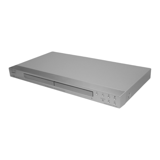
DVP-NS30/NS32/NS33/NS52P
Photo : DVP-NS30
Outputs
(Jack name: Jack type/Output level/
Load impedance)
LINE OUT (AUDIO): Phono jack/
2 Vrms/ 10 kilohms
DIGITAL OUT (OPTICAL)
(DVP-NS52P only):
Optical output jack/–18 dBm
(wave length 660 nm)
DIGITAL OUT (COAXIAL): Phono jack/
0.5 Vp-p/75 ohms
LINE OUT (VIDEO): Phono jack/
1.0 Vp-p/75 ohms
S VIDEO OUT
(DVP-NS52P only):
4-pin mini DIN/Y: 1.0 Vp-p,
C: 0.3 Vp-p (PAL),
0.286 Vp-p (NTSC)/75 ohms
COMPONENT VIDEO OUT
(Y, P
(DVP-NS52P only):
Phono jack/Y: 1.0 Vp-p,
P
/C
B
x
ao
u163
y
i
http://www.xiaoyu163.com
2 9
8
RMT-D175P
Q Q
3
6 7
1 3
1 5
SPECIFICATIONS
/C
, P
/C
)
B
B
R
R
, P
/C
: 0.7 Vp-p/75 ohms
B
R
R
co
.
9 4
2 8
RMT-D175P
AEP Model
DVP-NS30/NS32/NS33/NS52P
Russia Model
DVP-NS30/NS32/NS52P
UK Model
DVP-NS30/NS52P
0 5
8
2 9
9 4
2 8
General
Power requirements:
220–240 V AC, 50/60 Hz
Power consumption:
DVP-NS32/NS33: 10 W
DVP-NS52P: 11 W
Dimensions (approx.):
DVP-NS32/NS33:
430 × 43 × 237.2 mm
DVP-NS52P:
430 × 43 × 237.3 mm
(width/height/depth)
incl. projecting parts
Mass (approx.):
DVP-NS32/NS33: 1.92 kg
DVP-NS52P: 1.95 kg
Operating temperature: 5°C to 35°C
Operating humidity: 25% to 80%
Supplied accessories
See page 15
Specifications and design are subject to
change without notice.
m
CD/DVD PLAYER
9 9
9 9
Advertisement
Table of Contents

Related Manuals for Sony DVP-NS30


Summary of Contents for Sony DVP-NS30
- Page 1 DVP-NS30/NS32/NS33/NS52P 3 7 63 1515 0 RMT-D175P AEP Model SERVICE MANUAL DVP-NS30/NS32/NS33/NS52P Russia Model DVP-NS30/NS32/NS52P UK Model DVP-NS30/NS52P Photo : DVP-NS30 RMT-D175P L 13942296513 SPECIFICATIONS System Outputs General Laser: Semiconductor laser (Jack name: Jack type/Output level/ Power requirements: Signal format system: PAL/NTSC Load impedance) 220–240 V AC, 50/60 Hz...
- Page 2 REPLACE THESE COMPONENTS WITH SONY PARTS FONCTIONNEMENT. NE REMPLACER CES COMPOSANTS WHOSE PART NUMBERS APPEAR AS SHOWN IN THIS QUE PAR DES PIÈSES SONY DONT LES NUMÉROS SONT MANUAL OR IN SUPPLEMENTS PUBLISHED BY SONY. DONNÉS DANS CE MANUEL OU DANS LES SUPPÉMENTS PUBLIÉS PAR SONY.
-
Page 3: Table Of Contents
DVP-NS30/NS32/NS33/NS52P 3 7 63 1515 0 TABLE OF CONTENTS SERVICE NOTE DISASSEMBLY Disc Removal Procedure (at POWER OFF) ....4 2-1. Upper Case ..............2-1 2-2. Front Panel Assembly ........... 2-1 GENERAL 2-3. Loading Assembly ............2-2 2-4. Optical Device (KHM-310CAA/C2RP) ......2-3 Warning ................ -
Page 4: Service Note
DVP-NS30/NS32/NS33/NS52P 3 7 63 1515 0 SERVICE NOTE 1. DISC REMOVAL PROCEDURE (at POWER OFF) 1) Open dust cover to access to a hole insert a tapering driver into the aperture of the unit bottom, and move the lever of chuck can in the direction of the arrow A. -
Page 5: General
Sony dealer. Wipe the disc from the centre out. On operation • If the player is brought directly from a cold to a warm location, or is placed in a very damp room, moisture may condense on the lenses inside the player. -
Page 6: Index To Parts And Controls
DVP-NS30/NS32/NS33/NS52P 3 7 63 1515 0 Copyrights Notes Index to Parts and Controls • Notes about DVD+RWs/DVD+Rs, DVD-RWs/ This product incorporates copyright DVD-Rs or CD-Rs/CD-RWs protection technology that is protected by Some DVD+RWs/DVD+Rs, DVD-RWs/DVD- For more information, see the pages indicated in parentheses. -
Page 7: Guide To The Control Menu Display (Magic Pad)
DVP-NS30/NS32/NS33/NS52P 3 7 63 1515 0 Remote Guide to the Control Menu Display (Magic Pad) (scan/slow) buttons (35) Use the Control Menu to select a function and to view related information. Press DISPLAY repeatedly to turn on or change the Control Menu display as follows:... -
Page 8: Hookups
DVP-NS30/NS32/NS33/NS52P 3 7 63 1515 0 Step 3: Connecting the Video Cords Hookups Connect this player to your TV monitor, projector, or AV amplifier (receiver) using a video cord. Select one of the patterns A through D, according to the input jack on your TV monitor, Hooking Up the Player projector, or AV amplifier (receiver). -
Page 9: Step 4: Connecting The Audio Cords
DVP-NS30/NS32/NS33/NS52P 3 7 63 1515 0 ◆PROGRESSIVE VIDEO Step 4: Connecting the Audio Cords Select this setting when: – your TV accepts progressive signals, and, – the TV is connected to the COMPONENT VIDEO OUT jacks, and Select one of the following patterns A or B, according to the input jack on your TV monitor, –... -
Page 10: Playing Discs
DVP-NS30/NS32/NS33/NS52P 3 7 63 1515 0 Press X/x to select the setting that Press X/x to select the type of Press ENTER. matches your TV type. jack (if any) you are using to Quick Setup is finished. All connections and setup operations are complete. -
Page 11: Resuming Playback From The Point Where You Stopped The Disc (Resume Play/ 4. Multi-Disc Resume)
DVP-NS30/NS32/NS33/NS52P 3 7 63 1515 0 • When playing a DVD-RW in VR mode, the point Resuming Playback from where you stopped is cleared when the disc tray is Using the DVD’s Menu Selecting “ORIGINAL” or opened or the mains lead is disconnected. -
Page 12: Searching For A Scene
DVP-NS30/NS32/NS33/NS52P 3 7 63 1515 0 ◆ When Programme Play is activated ◆ When playing a DVD-RW Next, press X/x to select “03” under “C,” Follow step 5 for new programming. To • ON: shuffles titles, chapters, or tracks •... -
Page 13: Searching For A Title/Chapter/Track/Scene, Etc
DVP-NS30/NS32/NS33/NS52P 3 7 63 1515 0 ◆ When playing a VIDEO CD or Super Press ENTER. Watching frame by frame Searching for a Title/ VCD with PBC Playback The player starts playback from the (Slow-motion Play) SCENE Chapter/Track/Scene, selected number. -
Page 14: Sound Adjustments
DVP-NS30/NS32/NS33/NS52P 3 7 63 1515 0 When playing a DATA CD/DATA DVD (MP3 When playing a VIDEO CD (without PBC Checking the play information of Checking the information on the audio) functions), or CD the disc front panel display... -
Page 15: Tv Virtual Surround Settings (Tvs)
Example: the Dolby Surround Sound processed such as with built-in speakers on a stereo TV. TVS was developed by Sony to produce Dolby Digital 5.1 ch signals or the Dolby Digital sound’s surround sound for home use using just a monaural rear audio signals. -
Page 16: Adjusting The Playback Picture (Custom Picture Mode)
DVP-NS30/NS32/NS33/NS52P 3 7 63 1515 0 ◆ When playing a DATA CD (DivX Press X/x to select the setting you Adjusting the picture items in Adjusting the Playback video), or DATA DVD (DivX video) want. “MEMORY” The choices of DATA CD or DATA... -
Page 17: Playing Mp3 Audio Tracks Or Jpeg Image Files
DVP-NS30/NS32/NS33/NS52P 3 7 63 1515 0 When you insert a DATA CD/DATA DVD Selecting an album Selecting an MP3 audio track and press H, the numbered tracks (or files) Playing MP3 Audio are played sequentially, from 1 through 7. -
Page 18: Enjoying Divx Videos
DVP-NS30/NS32/NS33/NS52P 3 7 63 1515 0 z Hints Setting the pace for a slide show Selecting the slides’ appearance • To repeat both MP3 audio tracks and JPEG image files in a single album, repeat the same MP3 audio... -
Page 19: Using Various Additional Functions
DVP-NS30/NS32/NS33/NS52P 3 7 63 1515 0 Press X/x to select Selecting a DivX video file (PARENTAL CONTROL), then press Using Various Additional ENTER. After step 2 of “Selecting an album,” Functions The options for “PARENTAL press ENTER. CONTROL” appear. -
Page 20: Controlling Your Tv With The Supplied Remote
You can control the sound level, input source, If your TV is listed in the table below, set the MENU: ENGLISH and power switch of your Sony TV with the AUDIO: ORIGINAL appropriate manufacturer’s code. By using the Setup Display, you can make... -
Page 21: Custom Settings (Custom Setup)
DVP-NS30/NS32/NS33/NS52P 3 7 63 1515 0 ◆ 4:3 OUTPUT (DVP-NS52P only) ◆ PAUSE MODE (DVD VIDEO/DVD-RW Custom Settings Settings for the Sound only) This setting is effective only when you set (CUSTOM “TV TYPE” in “SCREEN SETUP” to Selects the picture in pause mode. -
Page 22: Additional Information
Digital video technology created by display. the operating manual that comes with the DivXNetworks, Inc. Videos encoded with , Contact your Sony dealer or local disc. DivX technology are among the highest authorized Sony service facility. quality with a relatively small file size. -
Page 23: Specifications
DVP-NS30/NS32/NS33/NS52P 3 7 63 1515 0 contain the same images (24 frames per DVD VIDEO (page 5) Specifications second) that are shown at movie theatres. A disc that contains up to 8 hours of moving Video based DVDs, such as television... - Page 24 DVP-NS30/NS32/NS33/NS52P 3 7 63 1515 0 MEMO L 13942296513 u163 1-20E 1-20 http://www.xiaoyu163.com...
-
Page 25: Disassembly
DVP-NS30/NS32/NS33/NS52P SECTION 2 3 7 63 1515 0 DISASSEMBLY Note: Follow the disassembly procedure in the numerical order given. 2-1. UPPER CASE 4 Tapping Screw 3 Tray Cover 6 Three Screws +BV3 (3-CR) 5 Tapping Screw 1 Dust Cover L 13942296513 2-2. -
Page 26: Loading Assembly
DVP-NS30/NS32/NS33/NS52P 3 7 63 1515 0 2-3. LOADING ASSEMBLY 1 Three Screws +BV3 (3-CR) 1 FMO-004 Flat Flexible Cable (CN101, 24P) 2 Loading Assembly 2 MD-108 Harness (CN201, 6P) 3 FMS-003 Flat Flexible Cable (CN202, 5P) L 13942296513 u163... -
Page 27: Optical Device (Khm-310Caa/C2Rp)
DVP-NS30/NS32/NS33/NS52P 3 7 63 1515 0 2-4. OPTICAL DEVICE (KHM-310CAA/C2RP) Note: Solder short land before remove the harness from 24 pin BU connector. 2 FFC Holder 6 Two Insulator 3 Optical Device 5 FMD-004 Flat Flexible Cable (CN101, 24P) -
Page 28: Switching Regulator
DVP-NS30/NS32/NS33/NS52P 3 7 63 1515 0 2-5. MV-045, IF 124 and ER-037 BOARDS Note: Caution Point on the PWB IF-124 When handling IF-124 PWB avoid contact with the sharp metal edge on the top side of Vacuum Fluorescent Display (ND401). -
Page 29: Interval Views
DVP-NS30/NS32/NS33/NS52P 3 7 63 1515 0 2-7. INTERNAL VIEWS TOP VIEW L 13942296513 MS-203 MOUNT Optical Device (KHM-310CAA/C2RP) u163 BOTTOM VIEW http://www.xiaoyu163.com... -
Page 30: Circuit Boards Location
DVP-NS30/NS32/NS33/NS52P 3 7 63 1515 0 2-8. CIRCUIT BOARDS LOCATION Power Board ER-037 Board MV-045 Board (CPU, Servo-DSP, AVDEC, DRIVE, VIDEO, AUDIO, POWER) IF-124 Board (INTERFACE) L 13942296513 u163 2-6E http://www.xiaoyu163.com... -
Page 31: Block Diagrams
DVP-NS30/NS32/NS33/NS52P SECTION 3 3 7 6 3 1 5 1 5 0 BLOCK DIAGRAMS 3-1. OVERALL BLOCK DIAGRAM ND401 *Except DVP-NS52P IC406 CNJ902 FUNCTION IR RECEIVER AUDIO/VIDEO OUTPUT J302 IC901 VFD DRIVER SWITCHING CIRCUIT VIDEO IC404 REGULATOR BUFFER EVER 3.3V... -
Page 32: Power Line Block Diagram
DVP-NS30/NS32/NS33/NS52P 3 7 6 3 1 5 1 5 0 3-2. POWER LINE BLOCK DIAGRAM POWER BLOCK MV-045 BOARD ER-037 BOARD (2P-P1-9054F-XX) (SEE PAGE 4-5 to 4-16) (SEE PAGE 4-23 to 4-24) (SEE PAGE 4-27 to 4-28) T101 D411... -
Page 33: System Control/Signal Processor Block Diagram
DVP-NS30/NS32/NS33/NS52P 3 7 6 3 1 5 1 5 0 3-3. SYSTEM CONTROL/SIGNAL PROCESSOR BLOCK DIAGRAM MV-045 BOARD (SEE PAGE 4-7 to 4-8) IC104 IC102 64M SDRAM 16M ROM 146,147,149~151,158~160 115,117,118,120,121,123~126,128~133,135 142 156 157 113 137 53~61,67~72,74~76,78,89,92,93 81~84,86~88,91 IOOE... -
Page 34: Rf/Servo Block Diagram
DVP-NS30/NS32/NS33/NS52P 3 7 6 3 1 5 1 5 0 3-4. RF/SERVO BLOCK DIAGRAM MV-045 BOARD (SEE PAGE 4-9 to 4-10) BASE UNIT KHM-310CAA/C2RP CN201 SLED D03- MOTOR D03+ 27 D04- IN1- SPINDLE IN2- D04+ MOTOR LIMIT IN3- IN4-... -
Page 35: Audio Block Diagram
DVP-NS30/NS32/NS33/NS52P 3 7 6 3 1 5 1 5 0 3-5. AUDIO BLOCK DIAGRAM MV-045 BOARD (SEE PAGE 4-13 to 4-14) IC405 DIGITAL D IN OUTPUT OPTICAL DVP-NS52P only Except DVP-NS52P J301 J302 SYSTEM CONTROL (SEE PAGE 3-5 to 3-6) -
Page 36: Video Block Diagram
DVP-NS30/NS32/NS33/NS52P 3 7 6 3 1 5 1 5 0 3-6. VIDEO BLOCK DIAGRAM IC304 wl C/BAR PB MV-045 BOARD (SEE PAGE 4-11 to 4-12) IC304 VIDEO BUFFER MUTE 2.5Vp-p 63.5usec VIDEO IN VIDEO OUT IC304 wj C/BAR PB... -
Page 37: Interface Control Block Diagram
DVP-NS30/NS32/NS33/NS52P 3 7 6 3 1 5 1 5 0 3-7. INTERFACE CONTROL BLOCK DIAGRAM IF-124 BOARD (SEE PAGE 4-19 to 4-20) CN401 IC 407 SW-10V EVER+5V 3.3V REGULATOR NS52P only SW+3.3V SYSRST D401 D407 SYSRST XIFCS PROG LED EVER+3.3V... -
Page 38: Printed Wiring Boards And Schematic Diagrams
DVP-NS30/NS32/NS33/NS52P SECTION 4 3 7 6 3 1 5 1 5 0 PRINTED WIRING BOARDS AND SCHEMATIC DIAGRAMS 4-1. FRAME SCHEMATIC DIAGRAM ER-037 BOARD 1-830-284-11 FFC (FEM-001) 1.0 pitch 1-963-090-11 Harness PM-119 CNXXX CN501 SW+8V SW+8V MTR GND MTR GND... -
Page 39: Printed Wiring Boards And Schematic Diagrams
DVP-NS30/NS32/NS33/NS52P 3 7 6 3 1 5 1 5 0 4-3. WAVEFORM 4-2. PRINTED WIRING BOARDS AND SCHEMATIC DIAGRAMS THIS NOTE IS COMMON FOR WIRING BOARDS AND SCHEMATIC DIAGRAMS. MV-045 BOARD (In addition to this, the necessary note is printed in each block) -
Page 40: Q Q
DVP-NS30/NS32/NS33/NS52P 3 7 6 3 1 5 1 5 0 MV-045 (CPU, Servo-DSP, AVDEC, DRIVE, VIDEO, AUDIO, POWER) PRINTED WIRING BOARD • : Uses unleaded solder. MV-045 BOARD SIDE A MV-045 BOARD SIDE B MV-045 BOARD A SIDE B SIDE... - Page 41 DVP-NS30/NS32/NS33/NS52P 3 7 6 3 1 5 1 5 0 For Schematic Diagram • Refer to page 4-5 for printed wiring board of MV-045 board. • Refer to page 4-4 for waveform MV-045 BOARD (1/5) CPU, SERVO-DSP, AVDEC -REF.NO.:1000 SERIES-...
- Page 42 DVP-NS30/NS32/NS33/NS52P 3 7 6 3 1 5 1 5 0 For Schematic Diagram • Refer to page 4-5 for printed wiring board of MV-045 board. • Refer to page 4-4 for waveform MV-045 BOARD (2/5) DRIVE -REF.NO.:1000 SERIES- XX MARK:NO MOUNT...
- Page 43 DVP-NS30/NS32/NS33/NS52P 3 7 6 3 1 5 1 5 0 For Schematic Diagram • Refer to page 4-5 for printed wiring board of MV-045 board. • Refer to page 4-4 for waveform MV-045 BOARD (3/5) VIDEO -REF.NO.:1000 SERIES- XX MARK:NO MOUNT...
- Page 44 DVP-NS30/NS32/NS33/NS52P 3 7 6 3 1 5 1 5 0 For Schematic Diagram • Refer to page 4-5 for printed wiring board of MV-044 board. • Refer to page 4-4 for waveform MV-044 BOARD (4/5) AUDIO -REF.NO.:1000 SERIES- XX MARK:NO MOUNT...
- Page 45 DVP-NS30/NS32/NS33/NS52P 3 7 6 3 1 5 1 5 0 For Schematic Diagram • Refer to page 4-5 for printed wiring board of MV-044 board. • Refer to page 4-4 for waveform MV-044 BOARD (5/5) POWER -REF.NO.:1000 SERIES- XX MARK:NO MOUNT...
- Page 46 DVP-NS30/NS32/NS33/NS52P 3 7 6 3 1 5 1 5 0 IF-124 (INTERFACE) PRINTED WIRING BOARD • : Uses unleaded solder. IF-124BOARD A SIDE For printed wiring board There are a few cases that the part printed on this diagram isn’t mounted in this model.
- Page 47 DVP-NS30/NS32/NS33/NS52P 3 7 6 3 1 5 1 5 0 For Schematic Diagram • Refer to page 4-17 for printed wiring board of IF-124 board. IF-124 BOARD INTERFACE -REF.NO.:1000 SERIES- XX MARK:NO MOUNT NO MARK:PB MODE MARKED:MOUNT TABLE 1 3 9 4 2 2 9 6 5 1 3...
- Page 48 DVP-NS30/NS32/NS33/NS52P 3 7 6 3 1 5 1 5 0 ER-037 (EURO OUT) PRINTED WIRING BOARD • : Uses unleaded solder. ER-037 BOARD A SIDE For printed wiring board There are a few cases that the part printed on this diagram isn’t mounted in this model.
- Page 49 DVP-NS30/NS32/NS33/NS52P 3 7 6 3 1 5 1 5 0 For Schematic Diagram • Refer to page 4-21 for printed wiring board of ER-037 board. ER-037 BOARD EURO OUT -REF.NO.:1000 SERIES- XX MARK:NO MOUNT NO MARK:PB MODE MARKED:MOUNT TABLE...
-
Page 50: Power Block (2P-P1-9054F) Printed Wiring Board
DVP-NS30/NS32/NS33/NS52P 3 7 6 3 1 5 1 5 0 POWER BLOCK PRINTED WIRING BOARD • : Uses unleaded solder. For printed wiring board POWER BOARD (2P-P1-9054F) There are a few cases that the part printed on this diagram isn’t mounted in this model. -
Page 51: Power Block (2P-P1-9054F)
DVP-NS30/NS32/NS33/NS52P 3 7 6 3 1 5 1 5 0 For Schematic Diagram • Refer to page 4-25 for printed wiring board of Power Board. POWER BOARD POWER BLOCK (2P-P1-9054F) -REF.NO.:1000 SERIES- XX MARK:NO MOUNT NO MARK:PB MODE MARKED:MOUNT TABLE... -
Page 52: Ic Pin Function Description
DVP-NS30/NS32/NS33/NS52P SECTION 5 3 7 63 1515 0 IC PIN FUNCTION DESCRIPTION 5-1. SYSTEM CONTROL PIN FUNCTION (MV-045 BOARD IC101) Pin No. Pin name Type Function AGND Ground pin for analog circuitry DVDA Analog Input AC coupled input path A... - Page 53 DVP-NS30/NS32/NS33/NS52P 3 7 63 1515 0 Pin No. Pin name Type Function OCSW Input Servo GPIO 1 EEWP Output EEPROM write Protect Control DVDD18 Power 1.8V power pin for internal digital circuitry Output PU Host address bit2 Output PU...
- Page 54 DVP-NS30/NS32/NS33/NS52P 3 7 63 1515 0 Pin No. Pin name Type Function IFSDI Input SMT Ext. CPV Serial data Input Output PU,SMT Default High IIC clock pin Output PU,SMT Default High IIC data pin Output PU,SMT UP3_0 Default High...
- Page 55 DVP-NS30/NS32/NS33/NS52P 3 7 63 1515 0 Pin No. Pin name Type Function Output DRAM address bit2 Output DRAM address bit3 DVDD18 Power 1.8V power pin for internal digital circuitry RVREF Analog Input Reference voltage for DDR DRAM RCLKB Output...
- Page 56 DVP-NS30/NS32/NS33/NS52P 3 7 63 1515 0 Pin No. Pin name Type Function DACVDDA Power 3.3V power for Video DAC circuitry Green or Y YG/YUV4 Output Video data output bit4 DACVSSA Ground Ground pin for Video DAC circuitry Blue or Cb...
- Page 57 DVP-NS30/NS32/NS33/NS52P 3 7 63 1515 0 Pin No. Pin name Type Function RFGND Ground Ground pin for RF digital circuitry Not used Not used Analog Output RF Offset cancellation capacitor connecting Analog Output RF Offset cancellation capacitor connecting RFGC...
-
Page 58: Test Mode
DVP-NS30/NS32/NS33/NS52P SECTION 6 TEST MODE 3 7 63 1515 0 6-1. EXECUTING IOP MEASUREMENT Wait until a hexadecimal number appear. Manual Adjust In order to execute IOP measurement, the following standard procedures must be followed. 1. Track Balance Adjust: 2. -
Page 59: Initializing Setup Data
DVP-NS30/NS32/NS33/NS52P 3 7 63 1515 0 Error code list (10) How to Clearing Emergency code Press [TOPMENU], [CLEAR] keys in this order. 01: Communication error (No reply from syscon) 02: Syscon hung up All emergency code are cleared. 03: Power OFF request when syscon hung up Emg. -
Page 60: Version Information
DVP-NS30/NS32/NS33/NS52P 3 7 63 1515 0 The Emergency history display screen will be restored 6-5. IF CON SELF DIAGNOSTIC FUNCTION soon. 1. IF-124 BOARD (IF CON) TEXT MODE Emg. History Check The IF-124 board (IF CON) test mode is the IF CON self- diagnosis mode. - Page 61 DVP-NS30/NS32/NS33/NS52P 3 7 63 1515 0 2-2. Operation of Auto Self Check When the Self Check mode becomes active at the AC Power ON or by key input, the test display of the following steps (1) to (4) is repeated.
- Page 62 DVP-NS30/NS32/NS33/NS52P 3 7 63 1515 0 2-3. Each Self Check Function Each Self Check function tests the FLD display, LED display, and key input. IC404: Pin No. (Signal) Input Voltage [V] PIN ef (AD1) PIN eg (O/C) PIN eh (STOP) PIN ej 0 - 0.20...
- Page 63 DVP-NS30/NS32/NS33/NS52P 3 7 63 1515 0 • Key code display (at input of key, key code: 0Ah) • At input of faulty voltage • When key is pressed double 2-3-3. Remote Commander Key Name Display and Key Code Display 2-3-3-1.
- Page 64 DVP-NS30/NS32/NS33/NS52P 3 7 63 1515 0 2-3-4. Communication Monitoring Display The communication state is monitored and displayed while the key name on the main unit and the remote commander is displayed. When the communication to the System Controller failed, VIDEO CD, DVD, and CD segments turn on.
- Page 65 DVP-NS30/NS32/NS33/NS52P 3 7 63 1515 0 2-3-6. FLD Grid Test Display and SHUTTLE Click Operation Test 2-3-6-1. Transition Keys in Self Check Mode • key on the remote commander • SHUTTLE on the remote commander during Grid Test display (This unit does not provide JOG/SHUTTLE, and therefore use another DVD remote commander having the JOG/SHUTTLE) 2-3-6-2.
- Page 66 DVP-NS30/NS32/NS33/NS52P 3 7 63 1515 0 (7G, 4G) (7G~3G, 1G) (7G~1G) L 13942296513 ANODE CONNECTION u163 http://www.xiaoyu163.com...
- Page 67 DVP-NS30/NS32/NS33/NS52P 3 7 63 1515 0 MEMO L 13942296513 u163 6-10E 6-10 http://www.xiaoyu163.com...
-
Page 68: Electrical Adjustment
DVP-NS30/NS32/NS33/NS52P SECTION 7 ELECTRICAL ADJUSTMENT 3 7 63 1515 0 This section describes procedures and instructions necessary for 7-1. POWER SUPPLY OUTPUT VOLTAGE adjusting electrical circuits in this unit. CHECK Instruments required: Mode Except standby Color monitor TV Instrument... -
Page 69: Adjustment Of Video System
DVP-NS30/NS32/NS33/NS52P 3 7 63 1515 0 7-2. ADJUSTMENT OF VIDEO SYSTEM Checking S Video Output S-Y <Purpose> Checking Video Level Check S-terminal video output. If it is incorrect, pictures will not be <Purpose> displayed correctly in spite of connection to the TV with a S-terminal Checking Video Level the NTSC/PAL standard, and if not correct, cable. - Page 70 DVP-NS30/NS32/NS33/NS52P 3 7 63 1515 0 Checking Component Video Output Y Checking Component Video Output R-Y <Purpose> <Purpose> This checks component video output Y. If it is incorrect, correct This checks component video output R-Y. If it is incorrect, correct brightness will not be attained when connected to, for instance, colors will not be displayed when connected to, for instance, projector.
- Page 71 DVP-NS30/NS32/NS33/NS52P 3 7 63 1515 0 MEMO L 13942296513 u163 7-4E http://www.xiaoyu163.com...
-
Page 72: Repair Parts List
DVP-NS30/NS32/NS33/NS52P SECTION 8 REPAIR PARTS LIST 3 7 63 1515 0 8-1. EXPLODED VIEWS The components identified by mark or dotted line with mark are critical for safety. NOTE: Replace only with part number speci- • -XX and -X mean standardized parts, so they •... - Page 73 DVP-NS30/NS32/NS33/NS52P 3 7 63 1515 0 Ref. No. Part No. Description Remark Ref. No. Part No. Description Remark 3-089-692-01 CASE, UPPER BLACK 3-089-692-21 CASE, UPPER SILVER 3-070-883-31 SCREW, TAPPING BLACK 3-070-883-41 SCREW, TAPPING SILVER 3-077-331-11 +BV3 (3-CR) 3-077-331-21 +BV3 (3-CR)
-
Page 74: Mechanism Deck Assembly
DVP-NS30/NS32/NS33/NS52P 3 7 63 1515 0 8-1-2. MECHANISM DECK ASSEMBLY ns : not supplied L 13942296513 not supplied Ref. No. Part No. Description Remark Ref. No. Part No. Description Remark A-6071-669-A LOADING ASSY(M) 3-088-371-01 BELT 4-674-137-11 SCREW (PTP2 x 5) 4-974-725-11 SCREW (M1.7 x 2.5), P... -
Page 75: Electrical Parts List
DVP-NS30/NS32/NS33/NS52P ER-037 3 7 63 1515 0 8-2. ELECTRICAL PARTS LIST The components identified by NOTE: mark or dotted line with mark • Due to standardization, replacements in • SEMICONDUCTORS are critical for safety. the parts list may be different from the In each case, u: µ, for example:... - Page 76 DVP-NS30/NS32/NS33/NS52P ER-037 IF-124 3 7 63 1515 0 Ref. No. Part No. Description Remark Ref. No. Part No. Description Remark R916 1-216-051-00 RES-CHIP 1.2K 1/10W <CHIP CONDUCTOR> R917 1-216-051-00 RES-CHIP 1.2K 1/10W JR401 1-216-295-91 SHORT CHIP R918 1-211-990-11 METAL CHIP 0.5%...
- Page 77 DVP-NS30/NS32/NS33/NS52P IF-124 MS-203 MV-045 3 7 63 1515 0 Ref. No. Part No. Description Remark Ref. No. Part No. Description Remark R426 1-216-073-91 RES-CHIP 1/10W A-1102-280-A MV-045 COMPLETE (NS30:AEP,UK) R427 1-216-083-00 RES-CHIP 1/10W A-1102-282-A MV-045 COMPLETE (NS30:RUS) R428 1-216-059-00 RES-CHIP 2.7K...
- Page 78 DVP-NS30/NS32/NS33/NS52P MV-045 3 7 63 1515 0 Ref. No. Part No. Description Remark Ref. No. Part No. Description Remark C161 1-162-970-11 CERAMIC CHIP 0.01UF 10.00% 25V C318 1-162-970-11 CERAMIC CHIP 0.01UF 10.00% 25V C162 1-162-970-11 CERAMIC CHIP 0.01UF 10.00% 25V...
- Page 79 DVP-NS30/NS32/NS33/NS52P MV-045 3 7 63 1515 0 Ref. No. Part No. Description Remark Ref. No. Part No. Description Remark <FERRITE> Q405 8-729-010-05 TRANSISTOR MSB709-RT1 Q406 8-729-024-89 TRANSISTOR MUN2213T1 FB106 1-469-324-21 FERRITE FB107 1-469-324-21 FERRITE Q407 6-550-137-01 TRANSISTOR2SD1938(F)-ST(TX).SO FB108 1-469-324-21...
- Page 80 DVP-NS30/NS32/NS33/NS52P MV-045 3 7 63 1515 0 Ref. No. Part No. Description Remark Ref. No. Part No. Description Remark R154 1-216-864-11 SHORT CHIP R249 1-216-864-11 SHORT CHIP R155 1-216-864-11 SHORT CHIP R250 1-216-864-11 SHORT CHIP R156 1-216-809-11 METAL CHIP...
- Page 81 DVP-NS30/NS32/NS33/NS52P MV-045 POWER BLOCK (2P-P1-9054F) 3 7 63 1515 0 Ref. No. Part No. Description Remark Ref. No. Part No. Description Remark R425 1-216-841-11 METAL CHIP 1/10W R1147 1-216-295-91 SHORT CHIP R426 1-216-817-11 METAL CHIP 1/10W R1150 1-216-827-11 METAL CHIP 3.3K...
- Page 82 DVP-NS30/NS32/NS33/NS52P 3 7 63 1515 0 Ref. No. Part No. Description Remark Ref. No. Part No. Description Remark <ACCESSORIES> 1-751-271-71 CORD, CONNECTION (AV) (NS30:UK/NS52P:UK) 2-581-864-11 MANUAL, INSTRUCTION (ENGLISH) (NS52P:UK) 2-581-864-21 MANUAL, INSTRUCTION (DANISH)(NS32:AE3/NS33:AE3/NS52P:AE3) 2-581-864-31 MANUAL, INSTRUCTION (DUTCH)(NS32:AE3/NS33:AE3/NS52P:AE3) 2-581-864-41 MANUAL, INSTRUCTION (SWEDISH)(NS32:AE3/NS33:AE3/NS52P:AE3)
- Page 83 DVP-NS30/NS32/NS33/NS52P 3 7 63 1515 0 L 13942296513 u163 2005C0800-1 Sony Corporation 2005. 03 Home Electronics Network Company. 9-874-857-11 Published by Video Design Department – 104 – 8-12 http://www.xiaoyu163.com...