
Related Manuals for NEC 2000 Series


Summary of Contents for NEC 2000 Series
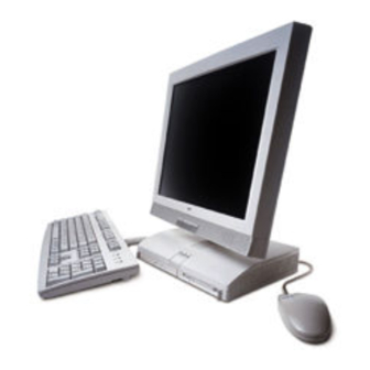
- Page 1 When Space is at a Premium and Flexibility is Key 2000 S OW E R AT E ® E R I E S U S E R ’ S G U I D E...
- Page 2 NEC is a registered trademark of NEC Corporation. PowerMate and MultiSync are registered trademarks and VistaScan is a trademark of NEC Corporation or one of its subsidiaries. All are used under license by NEC Corporation and/or one or more of its subsidiaries.
-
Page 3: Table Of Contents
Password Clear Jumper ... 1-12 Microdesktop Chassis ... 1-12 System Overview... 1-13 Hardware... 1-13 Software ... 1-14 Preloaded Microsoft Operating System ... 1-14 NEC OS Restore CD ... 1-14 NEC Application and Driver CD... 1-14 Security ... 1-15 Contents iii... - Page 4 Changing Hard Disk Drive Passwords...3-26 Using Hard Disk Drive Password Protection ...3-26 Moving the Hard Drive...3-27 FLASH Utility...3-27 NEC Application and Driver CD...3-28 NEC INFO Center ...3-29 NEC OS Restore CD...3-31 System Board Jumper Settings ...3-33 Intel Processor Serial Number Control Utility...3-34 System Requirements ...3-35...
- Page 5 4 Adding Expansion Devices Safety Precautions... 4-2 USB Devices ... 4-3 PC Cards ... 4-4 Inserting a PC Card... 4-4 Removing a PC Card ... 4-6 Memory Modules... 4-6 Checking System Memory ... 4-8 Installing a SO-DIMM Module ... 4-8 Removing a SO-DIMM Module...
- Page 6 Checking Your Monitor...A-12 Checking You...A-12 B System Specifications System Board ... B-2 System Processor... B-2 Random Access Memory (RAM) ... B-2 Cache Memory ... B-2 Read Only Memory (ROM) ... B-2 Calendar Clock... B-2 Input/Output (I/O) Features... B-3 Video Memory ... B-3 Sound Controller ...
-
Page 7: Using This Guide
T Chapter 3, Configuring the System, describes how to use the software utilities shipped with your system, including the BIOS Setup Utility, FLASH Utility, NEC Application and Driver CD, NEC INFO Center, NEC OS Restore CD, and Intel Utility. The chapter also includes information for setting system jumpers. -
Page 8: Text Conventions
workstation may pose a risk of serious injury. To reduce your risk of injury, set up and use your computer in the manner described in Appendix A, Setting Up a Healthy Work Environment. Text Conventions This guide uses the following text conventions. T Warnings, cautions, and notes have the following meanings: in serious personal injury or loss of life. -
Page 9: Related Documents
Release Notes is the result of extensive product testing. Your system also comes with the NEC INFO Center online documentation on the NEC Application and Driver CD. The NEC INFO Center is an online guide to your PowerMate system. It provides information about the system through the following online modules: Tour, User’s Guide, Questions, Solutions, and Services. -
Page 10: Reviewing System Features
Reviewing System Features Front Features Left Side Features Rear Features Bottom Features System Overview... -
Page 11: Front Features
workstation may pose a risk of serious injury. To reduce your risk of injury, set up and use the computer in the manner described in Appendix A, “Setting Up a Healthy Work Environment.” This chapter highlights system hardware and software features, and describes system security features. - Page 12 A – CD-ROM Drive B – CD-ROM Eject Button C – CD-ROM Drive Lamp D – CD-ROM Disc Emergency Eject E – Diskette Drive Lamp A – LCD Panel B – Decrease Brightness Level Button System unit front features LCD panel features C –...
-
Page 13: System Controls And Lamps
System Controls and Lamps System unit controls include a power/sleep button, power lamp, sleep lamp, and hard drive activity lamp. T Power/sleep button To turn system unit and LCD panel power on, press the power/sleep button. To turn off power, press the button and hold in place for four or more seconds before releasing. -
Page 14: Lcd Panel
LCD Panel The system comes with an LCD panel that you can adjust up or down and side-to-side for a comfortable viewing position. The panel uses a 15-inch, twisted nematic Thin Film Transistor (TFT) Super Video Graphics Array (SVGA) color screen. The screen has a brightness of 200 candlepower and a maximum resolution of 1024 x 768 pixels. -
Page 15: Hard Drive
Hard Drive The system comes with either a 6.0-gigabyte (GB) or a 12-GB enhanced intelligent device electronics (EIDE) hard drive. The drive features ultra direct memory access (DMA) 66 technology for fast data transfer. The drive is located inside the system unit, on the right side. The drive is not user accessible. -
Page 16: Audio Connectors
A – PC Card Slot 1 B – Slot 1 Card Eject Button C – Slot 2 Card Eject Button D – PC Card Slot 2 E – Fan Audio Connectors The system unit has the following audio connectors: T Microphone in jack Use this jack to connect a microphone for recording audio information in your data files. -
Page 17: Volume Control
Volume Control Use the volume control to adjust the volume of the system’s built-in speakers or optional headphone set. The speakers are located in the base of the LCD panel. You can also use the Windows sound software. To bring up the Windows volume control, double click the speaker icon on the taskbar (next to the system clock). -
Page 18: Universal Serial Bus Ports
A – PS/2 Mouse Port B – Kensington Lock Slot C – PS/2 Keyboard Port D – Printer Port E – Serial Port Universal Serial Bus Ports The system unit comes with two USB ports on the rear of the system unit. The ports allow you to easily and conveniently add plug and play USB devices without opening up the system. -
Page 19: Ps/2 Mouse Port
The system unit comes with a VGA connector on the rear of the system unit. Use this connector to connect an optional NEC MultiSync VistaScan™ monitor, or other VGA-compatible monitor with a 15-pin connector. You can also attach a projector with a 15-pin connector to this connector. -
Page 20: Lan Connector
LAN Connector Systems come with a local area network (LAN). Use the RJ-45 compatible LAN connector on the rear of the system to connect a network cable to the internal 100Base-TX/10Base-T network board. Bottom Features A panel on the bottom of the system unit covers the memory expansion sockets and the password clear jumper. -
Page 21: Memory Sockets
To clear and reset the password, see “Jumper Settings” and “Security Menu” in Chapter 3. Microdesktop Chassis The NEC Microdesktop chassis conforms to NEC’s Very-Small Form Factor and Flat Panel Display Specification. The microdesktop has the following features: T small size chassis that is 85 percent smaller and correspondingly... -
Page 22: System Overview
The system hardware and software deliver the performance and technologies needed for all your challenging tasks today and into the future. Hardware The PowerMate 2000 Series includes the following hardware features: T PC99 Compliance All the hardware in the system is certified by Microsoft compliant. -
Page 23: Software
Driver CD to install your applications, drivers, and NECC online documents. NEC Application and Driver CD Your system comes an NEC Application and Driver CD. Use this CD to install any or all of the software that comes with the system, including: T Microsoft ®... -
Page 24: Security
Wake-On LAN and remote reboot. T NEC INFO Center The NEC INFO Center an online version of this user’s guide, and Tour, Questions, Solutions, and Services modules. Select the Tour module to look at the documentation, tools, and services that come with the system. - Page 25 T Security Lock Slot The security lock slot on the rear of the system accepts a Kensington Security Standard connector or other locking device. Secure the locking device to the security lock slot and to an immovable object to protect your system from theft. T Hard Drive Security Your system supports password protection for the hard drive.
-
Page 26: Setting Up The System
Setting Up the System Cable Connections Startup Shutdown Power-Saving Operation System Care More Information... -
Page 27: Cable Connections
Note At the bottom of the NEC startup screen, the following message appears: Press F2 to enter BIOS Setup . If you want to enter the BIOS Setup Utility, immediately press F2 while the startup screen displays. (See Chapter 3, “Configuring the System,”... -
Page 28: Shutdown
If a problem occurs, a series of beeps might sound. If this happens repeatedly after powering on, power off the system and go to Chapter 5, “Solving System Problems.” The chapter provides helpful hints for solving system problems. If the system displays a message indicating that system settings have changed, run the BIOS Setup Utility (see Chapter 3, “Configuring the System”). -
Page 29: Power-Saving Operation
Click Start the computer depending on your operating system. If the system is configured with Windows 98 or Windows 2000, the system shuts down automatically after a short interval. If the system is configured with Windows NT, and after you perform a Windows shut down, power off the system by pressing and holding in the power button for four seconds or longer before releasing. -
Page 30: System Care
System Care The system is a durable system built for dependable use. With protective measures and proper care, you can prevent problems and promote the successful operation and long life span of the system. Protecting Your System From Damage There are several ways that you can protect the system from possible damage. -
Page 31: Keeping Your System In Good Condition
The recommended non-operating environment (shipping or storage) is from 14°F to 158°F (-10°C to 70°C). T After turning off power, wait about five seconds for the hard drive to spin down before you power on again. T Be sure that nothing is placed on top of the system AC adapter power cord. -
Page 32: Moving Or Shipping Your System
Be sure to save the original shipping materials in the unlikely event that you need to ship the system back for repair. To set up the system, follow the steps on the PowerMate 2000 Series Quick Setup poster that comes with the system. -
Page 33: More Information
More Information Once the system is up and running, we suggest that you do the following. T Install applications provided by NECC on the NEC Application and Driver CD. T See “Setting Up a Healthy Work Environment” in Appendix A. -
Page 34: Configuring The System
Configuring the System Configuration Tools and Utilities BIOS Setup Utility Hard Drive Security FLASH Utility NEC Application and Driver CD NEC INFO Center NEC OS Restore CD System Board Jumper Settings Intel Processor Serial Number Control Utility... -
Page 35: Configuration Tools And Utilities
T NEC Applications and Driver CD for installing the NECC-supplied applications and optional drivers T NEC INFO Center for quick access to information about your system T NEC OS Restore CD for restoring the operating system T jumper settings for clearing your password, should you forget it T Intel Processor Serial Number Control Utility for controlling the reading of the processor serial number. - Page 36 BIOS Setup (Power Menu) BIOS Setup (Power Menu) BIOS Setup (Main Menu) BIOS Setup (Main Menu) NEC Application and Driver CD (see “Installing the NEC INFO Center”) “Uninstalling the NEC INFO Center” NEC OS Restore CD BIOS Setup (Advanced Menu)
-
Page 37: Bios Setup Utility
To start the BIOS Setup Utility, follow these steps. Turn on or reboot the system. Press at the NEC startup screen ( screen). You have about five seconds to press Setup’s Main Menu window appears similar to the following screen. -
Page 38: How To Use Setup
Main Advanced System Time: System Date: Language Legacy Diskette A: Primary Master Primary Slave Secondary Master Secondary Slave Keyboard Features Boot-Time Diagnostic Screen: System Memory: Extended Memory: BIOS Revision: Processor Serial Number: Help ESC Exit How to Use Setup The Setup utility has a Main Menu window and six top-level menus with submenus (see the above figure). - Page 39 T Boot — Use this menu to set boot options, including restore on ac/power loss, set boot sequence, and assign drive letters to removable devices. T Exit Exits the Setup Utility with various save or discard options. Use the keys listed in the legend bar on the bottom of the Setup Menu to make the selections or exit the current menu.
-
Page 40: Main Menu
Pressing on any menu brings up the General Help window that describes the legend keys and their functions. Press to exit the current window. The following subsections describe the six top level menus and their submenus. Main Menu Choose the Main Menu by selecting Main in the legend bar on the Main Menu screen. -
Page 41: Main Menu Items
Menu Item Legacy Diskette A Primary IDE Master Primary IDE Slave Secondary IDE Master Secondary IDE Slave 3-8 Configuring the System Main Menu Items Settings (default is bold) Disabled 360 KB 5 1/4” 1.2 MB 5 1/4” 720 KB 3 1/2” 1.44/1.25 MB 3 1/2”... - Page 42 Menu Item Type Cylinders Heads Sectors Maximum Capacity Total Sectors Maximum Capacity Main Menu Items Settings (default is bold) User, Auto, None, CD-ROM, IDE/ATAPI Removable When set to Auto, the values for Cylinders, Heads, Sectors, Total Sectors, and Maximum Capacity are displayed but are read only. When set to Auto, the BIOS detects what the drive is capable of, not the translation mechanism that was used to format the drive.
- Page 43 Menu Item Multi-Sector Transfers LBA Mode Control 32-Bit I/O Transfer Mode Ultra DMA Mode 3-10 Configuring the System Main Menu Items Settings (default is bold) Disabled, 2, 4, 8, 16 sectors Determines the number of sectors per block for multi-sector transfers. When Type is Auto, value in Multi-Sector Transfers field is auto-detected and field is read only.
- Page 44 Menu Item Keyboard Features Numlock Key Click Keyboard auto-repeat rate Keyboard auto-repeat delay Legacy USB Support Boot-Time Diagnostics Screen System Memory Main Menu Items Settings (default is bold) Press Enter to check or change keyboard parameters. Auto, On, Off Selects the power-on state for Numlock. Disabled, Enabled Enables or disables key click.
-
Page 45: Advanced Menu
Menu Item Extended Memory BIOS Revision Processor Serial Number Advanced Menu Choose the Advanced Menu by selecting Advanced in the legend bar on the Main Menu screen. Other Advanced Menu options are available by selecting submenus. Use the arrow keys to select one of the Advanced Menu options and press to select a submenu. - Page 46 Menu Item Plug and Play OS Reset Configuration Data PCI Configuration PCI IRQ Line 1 PCI IRQ Line 2 PCI IRQ Line 3 PCI IRQ Line 4 Cache Memory Memory Cache Cache System BIOS Area Cache Video BIOS Area Advanced Menu Settings (default is bold) No, Yes Select Yes if you are booting a Plug and...
- Page 47 Menu Item Cache Base 0-512K Cache Base 512-640K Cache Extended Memory Area Cache C800-CBFF Cache CC00-CFFF Cache D000-D3FF Cache D400-D7FF Cache D800-DBFF Cache DC00-DFFF 3-14 Configuring the System Advanced Menu Settings (default is bold) Uncached, Write Through, Write Protect, Write Back Controls caching of 512K base memory.
- Page 48 Menu Item I/O Device Configuration Serial Port A Base I/O Address Interrupt Parallel Port Mode Base I/O Address Interrupt Advanced Menu Settings (default is bold) Press Enter to access the following submenus. Disabled, Enabled, Auto Setting at Enabled allows the user to configure the port.
- Page 49 Menu Item Floppy Disk Controller Base I/O Address Large Disk Access Mode Local Bus IDE Adapter QuickBoot Mode Sound DMI Event Logging Event Log Capacity Event Log Validity View DMI Event Log 3-16 Configuring the System Advanced Menu Settings (default is bold) Disabled, Enabled, Auto Setting at Enabled allows the user to configure the controller.
-
Page 50: Security Menu
Menu Item Clear All DMI Event Logs Event Logging Mark DMI Events As Read LANDesk ® Service Preboot Management Security Menu Choose the Security Menu by selecting Security in the legend bar on the Main Menu screen. Other Security Menu options are available by selecting submenus. - Page 51 Menu Item Supervisor Password Is User Password Is Set Supervisor Password Set User Password 3-18 Configuring the System Security Menu Items Settings (default is bold) Clear, Set Status only, user cannot modify. Supervisor password controls access to the BIOS Setup Utility.
- Page 52 Menu Item Security Mode Password on Boot Fixed Disk Boot Sector Diskette Access Security Menu Items Settings (default is bold) Press Enter to access the Security Mode. Use this mode to select Password (default), SmartCard, or FingerPrint. Press Enter to open the selected field.
-
Page 53: Power Menu
Menu Item Network Boot Setting Keyboard/Mouse Lock Virus Check Reminder System Backup Reminder Power Menu Choose the Power Menu by selecting Power in the legend bar on the Main Menu screen. Other Power Menu options are available by selecting submenus. Use the arrow keys to select one of the Power Menu options and press to select a submenu. - Page 54 Menu Item Power Savings Auto Suspend Timeout Hard Disk Timeout System Switch Resume On Modem Ring Power Menu Settings Settings (default is bold) Disabled, Customized, Maximum Power Savings, Maximum Performance Disabled setting turns off Power Management. Maximum Power Savings setting conserves the greatest amount of power.
-
Page 55: Boot Menu
Menu Item Resume On Time Resume Time Boot Menu Choose the Boot Menu by selecting Boot in the legend bar on the Main Menu screen. Other Boot Menu options are available by selecting submenus. Use the arrow keys to select one of the Boot Menu options and press to select a submenu. - Page 56 Menu Item On PME 1 through 4 Hard Drive Removable Devices Summary Screen Boot Menu Settings Settings (default is bold) Stay Off, Power On Controls how system responds to a PCI Power Management Enabled wake-up. Sets the bootable device order. Use the up or down arrow to select a device, then press the + or –...
-
Page 57: Exit Menu
Hard disk drive (HDD) password protection restricts access to the drive only if the drive is removed from the PowerMate 2000 series system and installed in another system. The system does not prompt you to enter your HDD passwords while the drive remains in the current system. -
Page 58: Establishing Hard Disk Drive Passwords
If you forget the master password and install the drive in another system, you cannot access the data on the hard drive. Once you set these passwords, NEC Computers Inc. has no capability of removing them. If you install the hard drive in another PowerMate system with hard disk drive security enabled, you must enter the password to allow access to the hard drive. -
Page 59: Changing Hard Disk Drive Passwords
If this PowerMate system does not support hard disk drive security, you cannot access the data on the hard drive. With hard disk drive security enabled on the original NEC PowerMate 2000 series system, the system boots normally. -
Page 60: Moving The Hard Drive
If you install the hard drive in another NEC PowerMate system with security enabled, you must enter the master password to access the hard drive. If the hard drive is installed in another NEC PowerMate 2000 system with security disabled, the system prompts you to enter the master password and then a new user password. -
Page 61: Nec Application And Driver Cd
BIOS defaults. Use the recorded Setup selections you made at the beginning of this procedure to set the parameters. NEC Application and Driver CD Use the NEC Application and Driver CD to install any or all of the NECC provided software, including T applications T utilities and device drivers T NEC INFO Center (online documentation). -
Page 62: Nec Info Center
NEC INFO Center. The INFO Center opening screen appears (see the following figure). Click on an NEC INFO Center module of your choice, depending on the information you want to see. We suggest you start with the Tour module. Configuring the System 3-29... - Page 63 Alternately, you can click . At the Control Panel, click Panel click NEC INFO Center To reinstall the NEC INFO Center, use the NEC Application and Driver CD.” 3-30 Configuring the System icon to remove all files related to the Unwise.exe...
-
Page 64: Nec Os Restore Cd
Remove any diskette or CD-ROM disc from your system. Power down your system and insert the bootable Master Restore diskette into the diskette drive and the auto-start NEC OS Restore CD into the CD-ROM drive. The system boots, the CD auto-starts, and the NEC Computers Inc. - Page 65 Insert the NEC Application and Driver CD or other update CD into the drive. If you are using the NEC Application and Driver CD, go to “NEC Application and Driver CD” earlier in this chapter to complete the update.
-
Page 66: System Board Jumper Settings
System Board Jumper Settings The system has an easily accessible jumper (7F4) for clearing your password if you forgot it. If you need to clear your password, set jumper 7F4 as follows. Wake a system in sleep mode, save and close any open applications, close Windows, power down, and unplug the system’s AC power adapter and any external options. -
Page 67: Intel Processor Serial Number Control Utility
Remove the jumper from pins 1 and 2 to clear your password. Place the jumper back on pins 1 and 2. Replace the access panel, plug in the AC power adapter, and power up the system. At the startup screen, press Navigate to the Security Menu and set your new password (see Chapter 3, “Configuring the System”... -
Page 68: System Requirements
T 2 megabytes of hard drive space. Installation The Intel Processor Serial Number Control Utility (version 1.0) comes on the NEC Application and Driver CD. Run where you unzip the file. Processor Serial Number The Intel processor serial number, a feature of the Pentium III processor, is an identifier for the processor. - Page 69 Why would I want to turn off my processor serial number? Intel believes the processor serial number can provide compelling benefits to users. They are developing features in conjunction with the processor serial number to allow responsible service providers to provide services which maintain your privacy.
-
Page 70: Technical Support
How can I tell if my processor serial number is turned on? The vast majority of Pentium III processor-based systems ship with the processor serial number enabled. The control utility allows you to check the status by: T Viewing the icon itself. The disabled icon shows a red circle with a white “x.”... -
Page 71: Adding Expansion Devices
Adding Expansion Devices Safety Precautions USB Devices PC Cards Memory Modules Parallel Printer External Monitor Serial Devices... -
Page 72: Safety Precautions
This chapter provides information for adding a variety of industry- standard expansion devices to your system. Included in the chapter are procedures for adding: T USB devices T PC cards T memory modules T printer T external monitor T external serial devices. Safety Precautions Observe safety rules when handling system components. -
Page 73: Usb Devices
T Dissipate static electricity before handling any system components (PC cards, memory modules) by touching a grounded metal object, such as the system unit unpainted bottom plate. If possible, use antistatic devices, such as wrist straps and floor mats. T Always hold a PC card or memory module by its edges. Avoid touching the contacts and components on the memory module. -
Page 74: Pc Cards
Connecting USB devices is easy. You don’t need to turn off the system to connect the devices. Simply match the connectors on the USB cable to the USB port on your system and the port on the USB device, then plug in the cable. - Page 75 To insert a PC card, follow these steps. Remove the PC card slot cover by pressing the eject button next to the slot. Pull the cover out of the slot and save it. Align the PC card so that the connector end points toward the PC card slot and that the printed label side is up.
-
Page 76: Removing A Pc Card
Use the software installed on your system to check PC card slot availability. In Windows 98 or Windows 2000, a PC card icon should be in the control panel or on the right side of the task bar. The icon shows which slot contains a PC card and which slot is empty. - Page 77 Use the following guidelines in selecting SO-DIMM types: T memory can be installed in one or two sockets T size of the SO-DIMMs can vary between sockets T speed of the SO-DIMMs must match the processor bus speed (100 MHz) T single- and double-sided SO-DIMMs are supported.
-
Page 78: Checking System Memory
Checking System Memory If you do not know how much memory is installed in your system, check the amount by using the following procedure. On the Windows 98, Windows 2000, or Windows NT 4.0 desktop, point to My Computer With the left mouse button, click the random access memory (RAM). - Page 79 Swivel the LCD panel to the right and position the unit on its side, as shown in the following figures. Positioning the LCD panel position the unit with the LCD panel facing up. Positioning the system for memory upgrade A – Memory Module Panel To prevent damage to the LCD panel, be sure to B –...
- Page 80 Remove the screw securing the memory module panel and remove the panel. Locate an empty module slot. If you need to remove one or both modules, see “Removing a SO-DIMM Module” in the next section. discharge by touching a metal part on the system unit. Install the SO-DIMM module as follows (see the following figure).
-
Page 81: Removing A So-Dimm Module
Removing a SO-DIMM Module If you need to remove a SO-DIMM module, use the following steps. the memory modules, wake a system in sleep mode, exit Windows, power down the system, and unplug the AC adapter power cord from the power source. -
Page 82: Parallel Printer
External Monitor You can add a standard Plug and Play external monitor to the system unit. The VGA connector on the back of the system unit supports any size NEC ® MultiSync monitor, NEC VistaScan™ monitor, or other VGA-compatible monitor with a 15-pin connector. -
Page 83: Solving System Problems
Solving System Problems Solutions to Common Problems How to Clean the Mouse... -
Page 84: Solutions To Common Problems
You may occasionally encounter a problem with the system. In most cases, the problem is one that you can solve yourself. The system has a built-in program that automatically checks its components when the system is powered on. If there is a problem, the system displays an error message. - Page 85 T Operating system not found error message displays when the system is started. If you left a CD in the CD-ROM drive, your system might not be able to boot. Try removing the CD and rebooting. T System does not boot and error message displayed on screen. Run the BIOS Setup Utility (see Chapter 3).
-
Page 86: Diskette Drive Problems
T System shuts off instead of going into sleep mode. You pressed and held in the power/sleep button for more than four seconds. For sleep mode, press in the button and immediately release. T System does not shut off after pressing the power/sleep button. You might not have pressed and held in the power/sleep button long enough. -
Page 87: Lcd Panel Problems
LCD Panel Problems Check the following problems to see the possible cause and solution. T Screen is dark or the display is hard to read. Adjust the LCD panel brightness control setting. (Note that the brightness setting returns to the system default setting on power down.) Press a key or move the mouse to take the system out of the power management mode. -
Page 88: Cd-Rom Drive Problems
CD-ROM Drive Problems Check the following problems to see the possible cause and solution. T The system does not see the drive. The drive designation is wrong and should be changed. The drive designation depends upon the storage device configuration in your system. -
Page 89: Speaker Problems
Speaker Problems Check the following problems to see the possible cause and solution. T Speaker volume is too low. Adjust the volume control on the side of the system unit. If the volume is still too low, adjust the volume through the system software. See your Windows Multimedia online help. - Page 90 Rotate the ball cover counterclockwise and remove the cover. Turn the mouse over so that the cover and ball fall into your palm. Clean the mouse as follows. Use tap water, or tap water and a mild detergent, to clean the mouse ball.
-
Page 91: Getting Services And Support
Getting Services and Support NECC Website NECC FTP Site Email/Fax Technical Support Service NECC Technical Support Services... -
Page 92: Necc Website
Support and links to vendor websites T automated email form for your technical support questions T Reseller’s area (password accessible). To access the NECC Home Page, enter the following Internet Uniform Resource Locator (URL) in your browser: www.nec-computers.com 6-2 Getting Services and Support... -
Page 93: Necc Ftp Site
NECC FTP Site You can use the Internet to access the NECC FTP (file transfer protocol) site to download various files (video drivers, printer drivers, BIOS updates, and Setup Disk files). The files are essentially the same files as on the NECC website. To access the NECC FTP site, enter the following Internet ftp address through your service: ftp.neccsdeast.com... -
Page 94: Necc Technical Support Services
NECC Technical Support Services NECC also offers direct technical support through its Technical Support Center. (NECC technical support is for U.S. and Canadian customers only; international customers should check with their sales provider.) Direct assistance is available 24 hours a day, 7 days a week. Call the NECC Technical Support Center, toll free, at Canada only) for the following support. -
Page 95: Setting Up A Healthy Work Environment
Setting Up a Healthy Work Environment Making Your Computer Work for You Arrange Your Equipment Adjust Your Chair Adjust Your Input Devices Adjust Your Monitor Vary Your Workday Pre-existing Conditions and Psychosocial Factors Checking Your Comfort: How Do You Measure Up? -
Page 96: Making Your Computer Work For You
workstation may pose a risk of serious injury. To reduce your risk of injury, set up and use your computer in the manner described in this appendix. Contact a doctor if you experience pain, tenderness, swelling, burning, cramping, stiffness, throbbing, weakness, soreness, tingling and/or numbness in the hands, wrists, arms, shoulders, neck, back, and/or legs. -
Page 97: Arrange Your Equipment
Arrange Your Equipment Arrange your equipment so that you can work in a natural and relaxed position. Place items that you use frequently within easy reach. Adjust your workstation setup to the proper height (as described in this appendix) by lowering the table or stand that holds your computer equipment or raising the seat height of your chair. -
Page 98: Adjust Your Chair
Adjust Your Chair Your chair should be adjustable and stable. Vary your posture throughout the day. Check the following: T Keep your body in a relaxed yet upright position. The backrest of your chair should support the inward curve of your back. T Use the entire seat and backrest to support your body. - Page 99 T Extend your lower legs slightly so that the angle between your thighs and lower legs is 90° or more. T Place your feet flat on the floor. Only use a footrest when attempts to adjust your chair and workstation fail to keep your feet flat. T Be sure that you have adequate clearance between the top of your thighs and the underside of your workstation.
-
Page 100: Adjust Your Input Devices
Adjust Your Input Devices Follow these points in positioning your keyboard and mouse. T Position your keyboard directly in front of you. Avoid reaching when using your keyboard or mouse. T If you use a mouse, position it at the same height as the keyboard and next to the keyboard. - Page 101 T Type with your hands and wrists floating above the keyboard. Use a wrist pad only to rest your wrists between typing. Avoid resting your wrists on sharp edges. T Type with your wrists straight. Instead of twisting your wrists sideways to press hard-to-reach keys, move your whole arm.
-
Page 102: Adjust Your Monitor
Adjust Your Monitor Correct placement and adjustment of the monitor can reduce eye, shoulder, and neck fatigue. Check the following when you position the monitor. T Adjust the monitor height so that the top of the screen is at or slightly below eye level. - Page 103 T Position the monitor at a 90° angle to windows and other light sources to minimize glare and reflections. Adjust the monitor tilt so that ceiling lights do not reflect on your screen. T If reflected light makes it hard for you to see your screen, use an anti- glare filter.
-
Page 104: Vary Your Workday
Vary Your Workday If you use your computer for prolonged periods, follow these instructions. T Vary your tasks throughout the day. T Take frequent short breaks that involve walking, standing, and stretching. During these breaks, stretch muscles and joints that were in one position for an extended period of time. -
Page 105: Pre-Existing Conditions And Psychosocial Factors
Note For more information on workstation setup, see the American National Standard for Human Factors Engineering of Visual Display Terminal Workstations. ANSI/HFS Standard No. 100-1988. The Human Factors Society, Inc., P.O. Box 1369, Santa Monica, California 90406. Pre-existing Conditions and Psychosocial Factors Pre-existing conditions that may cause or make some people more susceptible to musculoskeletal disorders include the following: hereditary... -
Page 106: Checking Your Keyboard
Checking Your Keyboard T Is your keyboard angled so your wrists are straight when you type? T Is your keyboard directly in front of you? T Do you avoid resting your wrists on sharp edges? T Do you press the keys gently and not bang on them? Checking Your Mouse T Is your mouse at the same height as the keyboard and next to the keyboard? - Page 107 For more information on workstation setup, see the American National Standard for Human Factors Engineering of Visual Display Terminal Workstations. ANSI/HFS Standard No. 100-1988. The Human Factors Society, Inc., P.O. Box 1369, Santa Monica, California 90406 This appendix was prepared in consultation with Dr. David Rempel of the University of California/San Francisco Ergonomics Program and Mr.
-
Page 108: System Specifications
System Specifications System Board System Peripherals Dimensions Power Operating Environment Compliance... -
Page 109: System Board
System Board The following sections give the specifications for major components on the system board. System Processor Type — Intel Pentium III Processor, 100-MHz FSB Support — 32-bit addressing, 64-bit data Secondary cache — 256 KB Socket — 370-pin Socket 370 Random Access Memory (RAM) Total system RAM —... -
Page 110: Input/Output (I/O) Features
Input/Output (I/O) Features Industry-standard interfaces integrated on system board: T Universal Serial Bus (USB) — two USB ports support two USB peripherals directly to the system. With appropriate connector, the system supports up to 127 daisy-chained devices. Supports 12 megabits (Mbs) per second. T Parallel —... -
Page 111: Sound Controller
Sound Controller All systems come with audio integrated on the system board. The audio is based on the Intel 82801AB (ICHO) chip and Yamaha YMF752 chip. Features include: T Compatible with Sound Blaster Pro and Microsoft T High quality SoundScape Wave Table Music Synthesizer T Plug and Play PCI compatibility T Stereo jacks —... -
Page 112: System Peripherals
System Peripherals The following sections give the specifications for system peripherals. LCD Panel Systems come with a 15-inch, high-resolution active matrix twisted nematic (TN) TFT Super Video Graphics Array (SVGA) color display. Features of the LCD panel include: T Brightness Adjustments —... -
Page 113: External Monitor
External Monitor The following resolutions are supported on an optional external monitor: T 320 x 200 (256/High color), vertical frequency depends on software T 320 x 240 (256/High color), vertical frequency depends on software T 640 x 400 (256/High color), vertical frequency depends on software T 640 x 480 (256/High color/True color), 60-/75-/85-Hz vertical frequency T 800 x 600 (256/High color/True color), 60-/75-/85-Hz vertical... -
Page 114: Diskette Drive
Diskette Drive Systems come with a Mobile Diskette Drive, 3 1/2-inch, 1.44 MB T Capacity — High density mode: Unformatted: Formatted: — Normal density mode: Unformatted: Formatted: T Data transfer rate — High density mode: 500/250 Kbit/sec — Normal density mode: 250/125 Kbit/sec Hard Drive Systems come with a Mobile 6.0-GB or a Mobile 12.0-GB EIDE Ultra DMA/66 hard drive. -
Page 115: Cd-Rom Drive
CD-ROM Drive Systems come with a Mobile ATAPI 24X MAX Slim CD-ROM drive. T Disc rotation speed — 5136 rpm T Data transfer rate (sustained) — 1548 KB/second to 3600 KB/second T Data transfer rate (burst) — 16.7 MB/second (PIO mode 4/multiword DMA mode 2) T Random access time —... -
Page 116: Dimensions
Dimensions System Base chassis — 10.75 inches (274.1mm) wide x 7.5 inches (192mm) deep x 2 inches (50.8mm) high Total height (with LCD panel) — 14.6 inches (375mm) Weight — approximately 12 lb. Keyboard Height — 1.6 in. (40.6 mm) Width —... -
Page 117: Compliance
Energy Star B-10 System Specifications FCC CFR 47 Part 15, Subpart B UL 1950 3rd edition C-UL C22.2 No.950-95 ICES-003 Issue 2, Revision 1 YMARK 2000 NEC Y2KTEST.EXE WHQL DMI 2.0 Self Certification Test Suite All systems are Energy Star Compliant... -
Page 118: Index
Index AC power adapter, 1-9 Acrobat reader, 1-15 AGP graphics, 1-13 Application and Driver CD, 3-28 Audio, 1-13 Audio connectors headphone jack, 1-7 line in jack, 1-7 microphone in jack, 1-7 Battery CMOS, 3-4 problems, 5-3 BIOS Advanced Menu, 3-12 Boot Menu, 3-22 Exit Menu, 3-24 FLASH ROM, 1-13... - Page 119 Disk error problems, 5-2, 5-4 Diskette FLASH, 3-27 Diskette drive description, 1-5 problems, 5-4 Display modes, 1-5, B-5, B-6 Documentation, online NEC INFO Center, 1-15 Drives CD-ROM, 1-6 diskette, 1-5 hard, 1-6 DVMT, 1-12, 1-13 Dynamic Video Memory Technology, 1-12...
- Page 120 2-7 NEC Application and Driver CD, 1-14, 1-15, 3-28 NEC INFO Center modules, 1-15 online, 3-29 uninstalling, 3-30 NEC OS Restore CD, 1-14, 3-31 NECC email/fax service, 6-3 FTP site, 6-3 technical support services, 6-4 Website, 6-2 Network setup, 2-2...
- Page 121 Sockets memory, 1-12 SO-DIMMs installing, 4-8 removing, 4-11 upgrading, 4-6 Software Acrobat Reader, 1-15 features, 1-14 Internet Explorer, 1-14 LANDesk, 1-15 NEC INFO Center, 1-15 Norton AntiVirus, 1-14 operating system, 1-14 Speakers location of, 1-6 problems, 5-7 volume control, 1-6...
- Page 122 LCD panel, 5-5 password, 5-4 performance problems, 5-3 power, 5-2 solutions, 5-2 speakers, 5-7 system problems, 5-2 time, incorrect, 5-3 Uninstalling, NEC INFO Center, 3-30 Universal serial bus, 1-9 Upgrading BIOS, 3-27 SO-DIMMs, 4-6 USB devices adding, 4-3 ports, 1-9...
- Page 123 VGA monitor connector, 1-10 VGA monitor/LCD panel simultaneous viewing, 1-5 Video memory, 1-12, 4-7 Virus scan software, 1-14 Volume control, 1-8 Website NECC, 6-2 Windows security, 1-16 Windows sound software, 1-8 Index-6...
-
Page 124: Regulatory Statements
Regulatory Statements The following regulatory statements include the Federal Communications Commission (FCC) Radio Frequency Interference Statement, compliance statements for Canada and Europe, battery disposal and replacement information, and the Declaration of Conformity. FCC Statement for United States Only expressly approved by the party responsible for compliance could void the user’s authority to operate the equipment. -
Page 125: Canadian Department Of Communications Compliance Statement
Canadian Department of Communications Compliance Statement This Class B digital apparatus meets all requirements of the Canadian Interference-Causing Equipment Regulations (pursuant to ICES-003 Issue 2, Revision 1). Avis de conformité aux normes du ministere des communications du Canada Cet equipment numérique de la Classe B respecte toutes les exigences du Reglement sur le matérial brouillage du Canada (en conformité... -
Page 126: Battery Disposal
Battery Disposal The CMOS battery is made of lithium. Contact your local waste management officials for other information regarding the environmentally sound collection, recycling, and disposal of the batteries. Mini-PCI FCC Registration Numbers If your system has a built-in mini-PCI modem, the FCC registration number of your system is H8NTAI-34309-ME-E REN 0.4. -
Page 127: Declaration Of Conformity
NEC Computers Inc. DECLARATION OF CONFORMITY We, the Responsible Party NEC Computers Inc. 15 Business Park Way Sacramento, CA 95828 declare that the product NEC PowerMate 2000 is in compliance with FCC CFR47 part 15 for Class B digital devices.