Motorola DCX3200 Installation Manual
Hide thumbs
Also See for DCX3200:
- User manual (57 pages) ,
- User manual (57 pages) ,
- User manual (45 pages)
Table of Contents
Advertisement
Quick Links
Advertisement
Table of Contents

Related Manuals for Motorola DCX3200


Summary of Contents for Motorola DCX3200
- Page 1 IN STALLAT ION MANUA L DCX3200 Installation Manual...
- Page 3 IMPORTANT SAFETY INSTRUCTIONS • Read these instructions. • Keep these instructions. • Heed all warnings. • Follow all instructions. • Do not use this apparatus near water. • Clean only with dry cloth. • Do not block any ventilation openings. Install in accordance with the manufacturer’s instructions. •...
- Page 4 FCC DECLARATION OF CONFORMITY Motorola Inc., Home and Network Mobility, 101 Tournament Drive, Horsham, PA 19044, 1-215-323-1000, declares that the DCX3200 receiver complies with 47 CFR Parts 2 and 15 of the FCC rules as a Class B digital device.
- Page 5 © 2008 Motorola, Inc. All rights reserved. No part of this publication may be reproduced in any form or by any means or used to make any derivative work (such as translation, transformation, or adaptation) without written permission from Motorola, Inc.
-
Page 7: Table Of Contents
CONTENTS 1 Introduction .................................. 1 Features ..................................2 Tuners................................. 2 Standard Audio/Video Features........................2 Standard Data Features ..........................2 Standard Miscellaneous Features ........................ 3 If You Need Help ..............................3 Calling for Repairs ..............................3 2 Overview ..................................5 Front Panel................................5 Rear Panel ................................ - Page 8 Recorder..................................18 Figure 3-6 Connecting the DCX Set-top to an A/V Receiver, Standard-Definition TV (SDTV), and VCR/DVD Recorder..................................20 Figure 3-7 Sample data devices you can connect to the DCX3200............... 21 TABLES Table 2-1 Front panel ..............................5 Table 2-2 Rear panel connections..........................6...
-
Page 9: Introduction
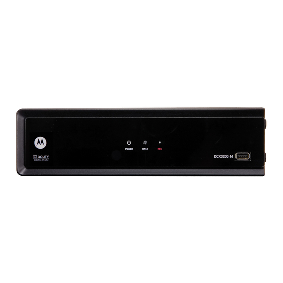
Ethernet and Universal Serial Bus (USB) 2.0 ports for future home networking applications • Adaptability to various software platforms As with all Motorola digital cable set-tops, the hardware features are enabled by core operating and third party application software. Figure 1-1 Front and Rear views... -
Page 10: Features
1 INTRODUCTION Features Tuners • One All Digital 1 GHz (54 to 1002 MHz) video tuner o MPEG-2 Main Profile @ High Level (High-Definition) o MPEG-4 H.264 (AVC) High-Definition decode • One dedicated tuner for the DOCSIS high-speed data services channel, up to 1 GHz •... -
Page 11: Standard Miscellaneous Features
Motorola Online: http://businessonline.motorola.com/ The TRC is on call 24 hours a day, 7 days a week. In addition, Motorola Online offers a searchable solutions database, technical documentation, and low-priority issue creation and tracking. For specific toll-free numbers when calling from outside the United States, please refer to the product manual or our Web page. -
Page 13: Overview
Illuminates to indicate one or more set-top boxes and or DVR devices are detected on the home network Rec — Unit is in record mode on a home network device (only available on DCX3200-M model) with MoCA option USB connector* *The availability of certain features is dependent upon application support. -
Page 14: M-Card
USB* 2.0 — High-Speed peripheral device connection Power connector * Availability of certain features is dependent upon application support. M-Card™ The M-Card is required to view cable television programs or interactive on-demand programs. The M-Card should not be removed from the DCX3200. -
Page 15: Installation
Cold Reset Method 1. Remove the set-top from its packaging. 2. Plug in a serial connector to the DCX3200 and open a terminal window. 3. AC power cycle the set-top. 4. When the words “Waiting for IR…” appear in the terminal window, press the Volume Down (–) button on the remote control. -
Page 16: Video Connection Options
Standard-Definition video output on the DCX3200. Video SDTV only If the TV does not have an S-Video input, use the composite video (composite) (video) output. SDTV only If the TV only has a coaxial RF input, connect it to the DCX3200 RF out connector. -
Page 17: Audio Connection Options
AUDIO L and R outputs to connect to the audio receiver. Connect the stereo audio cable to the AUDIO L and R connectors on the DCX3200 and the audio left and right connectors on the TV. If the equipment supports it, use either the optical S/PDIF or coaxial digital S/PDIF output (there is no difference in audio quality between the two) instead of the AUDIO L and R outputs. -
Page 18: Connecting Hdtv - Single Connection For Video/Audio
3 INSTALLATION 2. Determine if you are connecting the audio to a home theater receiver or directly to the TV: • For an HDMI™ or IEEE-1394 video connection, no additional audio connections to the TV are required. • If the receiver or TV has a digital audio (S/PDIF) input, use the digital audio outputs. -
Page 19: Ieee-1394
3 INSTALLATION Figure 3-1 Connecting the DCX Set-top to an HDTV — Single Connection for Video/Audio Choose HDMI IEEE 1394 DCX3200 AUDIO DIGITAL AUDIO Because HDMI and IEEE-1394 M-card TM DEVICE ONLY provide both video and audio IEEE EXT IR... -
Page 20: Connecting Hdtv - Separate Video/Audio Connections
If the TV does not have digital audio inputs: • Connect the stereo audio cable to the AUDIO L and R connectors on the DCX3200 Series set-top and the audio left and audio right connectors on the HDTV. If the TV supports a digital audio input: •... -
Page 21: Figure 3-2 Connecting The Dcx Set-Top To An Hdtv - Separate Video/Audio
The baseband connections are not necessary because the digital audio port provides a single audio interface for digital channels. Note: If the A/V receiver includes HDMI™ inputs & output(s) then the DCX3200 HDMI™ output can be directly connected to the A/V receiver. -
Page 22: Connecting An A/V Receiver - Audio
3 INSTALLATION Connecting an A/V Receiver — Audio There are several options available for audio connections to the A/V receiver: • Digital audio (OPTICAL S/PDIF) • Digital audio (COAXIAL S/PDIF) • Stereo audio (AUDIO L and R) If the A/V receiver supports it, the optical (S/PDIF) or coaxial (S/PDIF) audio outputs may be used in place of the stereo audio outputs (AUDIO L and R). -
Page 23: Figure 3-3 Connecting The Dcx Set-Top To An A/V Receiver - Audio
3 INSTALLATION Figure 3-3 Connecting the DCX Set-top to an A/V Receiver — Audio Choose Choose Digital audio Digital audio L/R audio optical coaxial DCX3200 AUDIO DIGITAL AUDIO M-card TM DEVICE ONLY IEEE EXT IR 1394 SERIAL POWER RF OUT... -
Page 24: Connecting A Standard-Definition Tv (Sdtv)
Connecting HDTV — Separate Video/Audio Connections. Figure 3-4 Connecting a Standard-Definition TV (SDTV) Choose Choose L/R audio S-Video Video RF audio/video (composite) (coax) DCX3200 AUDIO DIGITAL AUDIO M-card TM DEVICE ONLY IEEE EXT IR 1394 SERIAL POWER RF OUT VIDEO OUT... -
Page 25: Connecting A Standard-Definition Tv (Sdtv) And Vcr/Dvd Recorder
DCX3200 Series set-top and the INPUT AUDIO L and R connectors on the stereo VCR. 2. Connect a video cable to the VIDEO OUT connector on the DCX3200 Series set-top and the INPUT VIDEO connector on the stereo VCR. 3. Connect a stereo audio cable to the OUTPUT AUDIO L and R connectors on the Stereo VCR and the INPUT AUDIO LEFT and RIGHT connectors on the Stereo TV (SDTV). -
Page 26: Figure 3-5 Connecting The Dcx Set-Top To An A/V Receiver, Standard-Definition Tv (Sdtv), And Vcr/Dvd Recorder
3 INSTALLATION Figure 3-5 Connecting the DCX Set-top to an A/V Receiver, Standard-Definition TV (SDTV), and VCR/DVD Recorder L/R audio Video (composite) DCX3200 AUDIO DIGITAL AUDIO M-card TM DEVICE ONLY IEEE EXT IR 1394 SERIAL POWER RF OUT VIDEO OUT... -
Page 27: Connecting An A/V Receiver, Tv, And Vcr
3 INSTALLATION Connecting an A/V Receiver, TV, and VCR 1. Connect a stereo audio cable to the AUDIO OUT L and R connectors on the DCX set-top and the INPUT L and R connectors on the A/V receiver. 2. Connect a video cable to the video out connector on the DCX set-top and the cable/TV video connector on the A/V receiver. -
Page 28: Figure 3-6 Connecting The Dcx Set-Top To An A/V Receiver, Standard-Definition Tv (Sdtv), And Vcr/Dvd Recorder
3 INSTALLATION Figure 3-6 Connecting the DCX Set-top to an A/V Receiver, Standard-Definition TV (SDTV), and VCR/DVD Recorder Choose Video L/R audio S-Video (composite) DCX3200 AUDIO DIGITAL AUDIO M-card TM DEVICE ONLY IEEE EXT IR 1394 SERIAL POWER RF OUT... -
Page 29: Data Device Connections
3 INSTALLATION Data Device Connections The DCX3200 provides optional high-speed data services such as Internet access, USB, Ethernet, and more. The functionality of each data device port requires, and depends on, installed application software. The DCX3200 rear panel provides the following data ports: USB 2.0... -
Page 30: Operational Check For The Remote Control
• Turn the TV on When using an HDMI™ connection between the DCX3200 and the television, be sure to have the cable connected and the TV powered on before adjusting the video settings. Motorola recommends using HDMI™ cables less than 20 meters long. - Page 31 An example of the User Settings menu when the HDMI™ output is connected Note: The User Settings Menu indicates whenever an HDMI™ connection is in place between the DCX3200 and another device. When the HDMI™ connection is not being used, the User Settings Menu will update to reflect this: An example of the User Settings menu when the HDMI™...
- Page 32 TV Type The TV Type setting allows you to specify the style of television connected to the DCX3200. Options include 16:9, 4:3 LETTERBOX, and 4:3 PAN SCAN. By default, the 16:9 option is selected. The options are used as follows: •...
- Page 33 Note 2: The DCX3200 can detect when the HDMI™ connection is in use. If you are not using the HDMI™ connection on the DCX3200, the “HDMI/YPbPr Output” setting will display as ”YPbPr Output” in the User Settings Menu.
- Page 34 YPbPr output. When using the DCX3200 in Native mode, these two formats are disabled and inaccessible if there is no HDMI™ connection in place. Note 2: When connecting the DCX3200 to an HDMI™ (or DVI) TV, the TV provides the DCX3200 with its list of supported video formats. The DCX3200 will automatically place a check next to the formats in the checklist that it can verify are supported by the TV.
- Page 35 1080p30 and/or 1080p24 formats. The DCX3200 also does not support the 1080p60 video format. Note 5: The DCX3200 will provide 480i format video on the YPbPr output whenever 1080p30 or 1080p24 format video is being provided on the HDMI™...
- Page 36 3 INSTALLATION 1. With an HDMI™ connection in place, power off the DCX3200 and then immediately press the key on the remote control. This will display the main User Settings MENU menu. Move the cursor next to the “Additional HDMI Settings” option and press the ►...
- Page 37 DCX3200. • L-PCM designates that the DCX3200 will provide all audio in the Linear Pulse Code Modulation digital audio format. The L-PCM format is widely supported by most HDMI™ televisions and home theater receivers.
- Page 38 The Additional HDMI™ Settings menu options are: Setting Description Service Sets the service used by the DCX3200 to render (draw) the closed captions: Selection • Analog: CC1, CC2, CC3, CC4, T1, T2, T3, or T4. The default is CC1. •...
-
Page 39: Graphics Overlaying The Video
Defaults Graphics Overlaying the Video The DCX3200 can generate graphics that overlay the video programming or fill the entire television screen. Common examples include on-screen menus (such as the User Setting menu), closed captions, and IPG. The DCX3200 overlays these graphics whenever you open a menu, enable closed captions, or scroll through a program grid. -
Page 41: Diagnostics
All sample displays are illustrative; actual data may differ from the examples. Using the Diagnostics To use the diagnostics: 1. Ensure that the DCX3200 is installed with the Thin Client software and that it is connected to an AC outlet. 2. Ensure the set-top is powered on. -
Page 42: General Status
4 DIAGNOSTICS General Status This diagnostic displays system status information on the OSD. The information is updated each time the diagnostic is displayed. - Page 43 EP18 Driver initialization failure Connected A DCX-operations connect or disconnect message determines whether the State DCX3200 is CONNECTED or DISCONNECTED. Platform ID A unique 16-bit hexadecimal number that identifies the platform image (also called the ROM ID). Family ID The manufacturer and product family, in hexadecimal.
-
Page 44: Purchase Status
The last acknowledged sequence number of a purchase sent by the controller. It is a 16-bit, unsigned hexadecimal number. Last RB Time The last time the DCX3200 attempted to report back purchases to the controller, in GPS seconds. IPPV Status If IPPV is enabled, the IPPV status indicator is on. -
Page 45: Out-Of-Band (Oob) Status
4 DIAGNOSTICS Field Description Credit Total Credit used for purchase processing Debit Total Debit used for purchase processing Out-Of-Band (OOB) Status This diagnostic indicates the out-of-band control channel status on the OSD. The information is updated every 5 seconds. The Out-Of-Band Status fields are: Field Description Indicates the OOB tuner center frequency, from 70 to 130 MHz. -
Page 46: Agile Oob Tuner Hunting
Displays the conditional access stream for the DCX3200, in hexadecimal. Provider ID EMM PID Displays the packet identifier (PID) stream the DCX3200 tunes to for EMM data, in hexadecimal. Network Displays the network PID to which the DCX3200 is tuned to receive network messages, in hexadecimal. -
Page 47: In-Band Status
4 DIAGNOSTICS 1. When in the OOB Receiver Status Diagnostic, press the MENU button on the remote control to enter the frequency selection mode. The OSD displays a new “MAN FREQ” line at the bottom of the screen, which indicates the last known carrier frequency. - Page 48 Indicates the number of correctable and uncorrectable digital multiplex errors, up to 9999. It is updated every 5 seconds and reset each time the DCX3200 is power cycled or another digital multiplex is tuned. The maximum value displayed is 9999, even if there were more than 9999...
-
Page 49: Unit Address
Description TvPC Indicates whether the TvPC renewable security system is installed: Installed NO — TvPC is not installed (Note: the DCX3200 does not include a TvPC slot.) CableCARD YES — CableCARD is inserted. Inserted NO — CableCARD is not inserted. -
Page 50: Separable Security
4 DIAGNOSTICS Field Description Serial The Host Serial Number is displayed on the Unit Address diagnostic screen. Number The DOCSIS, Ethernet, 1394, USB, and MAC addresses are stored in protected Addresses flash and displayed in hexadecimal. Separable Security This diagnostic displays information on the inserted M-CARD and CableCARD Interface with the DCX. -
Page 51: Current Channel Status
4 DIAGNOSTICS Field Description • HOST SIGN FAILED if status is not bound because of failure to verify Host’s SIGN. • AUTH KEY FAILED if status is not bound because of failure to match AuthKey from the Host Device. • FAILED if binding failed for other reasons. - Page 52 4 DIAGNOSTICS The Current Channel status fields are: Field Description Type Indicates whether the channel is analog or digital: Description DIGITAL Digital Status Indicates the current status of channel acquisition. Description Acquired Service has been acquired and is playing, but stream components may not be locked yet if the service is digital.
- Page 53 4 DIAGNOSTICS Field Description Service Service number from the secure processor. It is a one bit value; 0 or 1. Status Service status from the secure processor. It is a decimal value from 0 to 3. Service ID from the secure processor. It is a hexadecimal value. First 2 bytes indicate MPEG service number and the last byte indicates another unique identifier.
-
Page 54: Rf Modem (Upstream)
Center The RF modem center frequency is displayed on the OSD in MHz. Frequency Requested The value in dB assigned to the DCX3200 during RF leveling (blank if it is Power Level not configured). Actual Power The power level is displayed in dB on the OSD or is blank if the power level Level has not been set. - Page 55 4 DIAGNOSTICS The Code Modules fields are: Field Description Boot Code The boot code version in ASCII format. Platform Built The date platform software was built. Version The firmware version and build date in ASCII format. Processor The digital secure processor version in ASCII format. Analog The analog secure processor version in ASCII format.
-
Page 56: Memory Configuration
The object identifier The Local Origination states whether the object is located locally on the set- top. Memory Configuration This diagnostic displays the DCX3200 memory configuration. The information is updated when you display the diagnostic. The Memory Configuration fields are: Field... - Page 57 4 DIAGNOSTICS Field Description AUDIO S/PDIF Indicates S/PDIF Mode as set by application software. OSD Display Description Audio S/PDIF mode is not applicable. IEC958PCM PCM audio selected. ® ® Dolby Digital For Dolby Digital selection, the following speaker selection is set: right front or left front right front and left front right front and left front and center...
- Page 58 4 DIAGNOSTICS Field Description UNMUTED Displayed if mute method is not selected. MUTE to Displayed if the mute method includes stopping video and presenting a still frame, STILL similar to a pause function. MUTE to Displayed if mute method presents a black screen. BLACK Captions The captions mode displays captions present on the service.
- Page 59 4 DIAGNOSTICS Field Description Closed Caption service T 1 Closed Caption service T 2 Closed Caption service T 3 Closed Caption service T 4 Primary Lang Primary language established by the provider (default, Service 1) Second Lang Secondary language established by the provider (Service 2) Service 3 Set by the provider Service 3.
-
Page 60: Interface Status
4 DIAGNOSTICS Interface Status The Interface Status diagnostic displays when running in Thin Client. The information on the OSD is updated when you display the diagnostic. - Page 61 4 DIAGNOSTICS...
- Page 62 The list displays all of the formats that the DCX3200 could read, up to a maximum of 12 formats. If the DCX3200 cannot read any formats, EDID Data is blank. An asterisk (*) after the aspect ratio means the DCX3200 supports the format.
-
Page 63: User Setting Status
4 DIAGNOSTICS User Setting Status This diagnostic displays the user settings. The format may vary. The information is updated when you display the diagnostic. The User Setting Status fields are: Setting Description TV Type Allows you to specify the style of television connected to the DCX set-top. Options include 16:9, 4:3 LETTERBOX, and 4:3 PAN SCAN. - Page 64 4 DIAGNOSTICS Setting Description 4:3 Override The 4:3 Override setting allows you to specify the video output format of the DCX set-top when it is tuned to a Standard-Definition. Options include 480i, 480p, Stretch, and Off. By default, the 480i option is selected. The options are used as follows: •...
-
Page 65: Docsis Status
4 DIAGNOSTICS DOCSIS Status This three-screen diagnostic displays status information for the embedded cable modem (eCM):... - Page 66 4 DIAGNOSTICS The fields are: Field Description DOCSIS For a DOCSIS-enabled set-top, YES. Otherwise, NO. Enabled Acquire DS The DOCSIS downstream channel acquisition status: Channel • YES — The downstream channel is acquired. • NO — The set-top is acquiring the downstream channel. •...
- Page 67 4 DIAGNOSTICS Field Description eCM Registered Displays whether the embedded cable modem has registered with the cable modem termination system (CMTS): • YES — DOCSIS registration is complete. • NO — DOCSIS registration is in progress, or the set-top could not register.
- Page 68 DOCSIS is not enabled, 0.000 is displayed. Known MAC Displays up to 32 MAC addresses learned by the DCX3200 cable modem, Addresses including the Set-Top MAC and future MAC addresses assigned by DSG, in hexadecimal format xx:xx:xx:xx:xx:xx on two screens if necessary.
-
Page 69: Application Specific Information
4 DIAGNOSTICS Application Specific Information This diagnostic displays information about application servers: The fields are: Field Description Server # Name The application server name of up to 14 alphanumeric characters. It is blank if the value is invalid or no value can be retrieved. Srvr # IP Addr The application server’s IP address in dotted-decimal format xxx.xxx.xxx.xxx;... - Page 70 Upstream ID A four-digit decimal value from 0000 to 9999 assigned by the DAC 6000 to the DCX3200. 0000 is displayed if the Upstream ID is not configured or if it is unknown. Downstream A four-digit decimal value from 0000 to 9999 assigned by the DAC 6000 to the DCX3200.
- Page 71 Cntr count limit. It is reset by the successful upstream transmission of a cell: for example, when the DCX3200 receives an ACK. If the counter reaches the MAC abort count limit, the DCX3200 assumes the MAC layer is unavailable due to noise, congestion, or some other problem. The DCX3200 stops transmitting data upstream, reports an error to the calling function, and attempts to re-enter the network using the initialization process.
-
Page 73: Troubleshooting
5 TROUBLESHOOTING Troubleshooting guidelines follow. If problems still occur after performing the diagnostics, call the TRC for assistance as described in the Introduction. Problem Possible Solution The DCX set- The DCX set-top may have received a software update and may not power on top will not while the new software is being installed. - Page 74 4:3 video). picture • If the DCX3200 is connected to a widescreen TV, verify that the TV TYPE is set to 16:9 in the User Settings menu. Many HD programs are broadcast in pillar-box format with black bars to the left and right of the picture.
- Page 75 This is called a “hybrid” aspect ratio and results in a black border surrounding the video on a 4:3 TV. Because this is part of the broadcast, the DCX3200 cannot correct the video. You may be able to minimize the border using the zoom feature on the TV.
- Page 77 Motorola, Inc. 101 Tournament Drive Horsham, PA 19044 U.S.A. http://www.motorola.com 547051-001-a 11/08...