
Summary of Contents for U.S. Brig Niagara
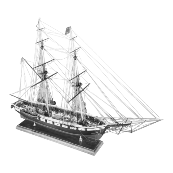
- Page 1 I N S T R U C T I O N M A N U A L Niagara U.S. BRIG TECHNICAL CHARACTERISTICS SCALE: 3/16" = 1' (1:64) Overall length: 43" Overall height: 27" Overall width: 11" MODEL SHIPWAYS KIT NO. MS2240...
-
Page 2: Brief History
The reconstruction was completed in 1990. The new Niagara hull length is 123 feet with a 32 foot beam. Draft at the stern is 10 feet 3 inches, and she dis- places 297 tons. The tons burthen (old measure) is 492 60/95 tons. In 1813, the ship carried 155 officers and men, and was armed with eighteen 32-pounder carronades and two long 12-pounders. -
Page 3: Table Of Contents
ABLE OF CONTENTS ABLE OF CONTENTS Brief History Eyebolts and Cleats Cannons Introduction and Credits Rudder and Tiller Before You Begin Tools Needed To Start Construction Boat Davits and Slides Ship's Boats 22,23 How to Work With Plans And Parts Ship's Name Painting and Staining The Model Hammock Rails and Stanchions... -
Page 4: Introduction And Credits
Ben Lankford Model by William Hitchcock Model Shipways developed the Niagara kit in 1996. Plans are based on the 1990 reconstruction drawings, research sketches, and specifications prepared and supplied by the designer, naval architect Melbourne Smith, International Historical Watercraft Society, Annapolis, Maryland. Many as-built features deviating from the plans are incorporated. -
Page 5: Before You Begin
Before You Begin Niagara is a beautiful, interesting ship and makes a splendid model. Assembling the plank-on-bulkhead hull develops an understanding of how real ships are built, while laser-cut parts assure an accurate shape. The kit contains more than 150 laser-cut wood parts. -
Page 6: How To Work With Plans And Parts
This Sheet 2 shows the bulkheads. They are The Niagara kit is manufactured to a makeshift tool works quite well. similar to a ship's body plan or sections, scale of 3/16"... - Page 7 450º F. Some Niagara doesn't require a great deal of brands are mixed with 3% or 4% silver, Next, cut a small piece of solder and lay soldering.
-
Page 8: Painting And Staining The Model
Painting And Staining The Model Beginning with directions on applying spackling compound, such as Pic-n-Patch finish the completed model with a flat, finishes may seem strange, but it isn't. or DAP, to fill any scratches and defects, clear coat. It provides durability and seals Much time and effort can be saved and then sand and prime again. - Page 9 (Model based paints with water creates surface have superb adhesion and won’t bleed Shipways sells a Niagara paint set.) If tension problems, resulting in poor cov- when firmly applied (burnishing is rec- another manufacturer's paints are used, erage and spray atomization.
-
Page 10: Stage 1: Framing The Plank-On-Bulkhead Hull
Fig 1-1 Assembling the Center Keel STAGE 1 Straight edge to align reference line Wax paper or plastic wrap Framing the Plank-on-Bulkhead Hull Weight 1. Bending Wood Building a P-O-B hull requires bending some wood without distorting its Glue joint desired position (doing so stresses glue let dry 24 hours joints and fasteners). - Page 11 (Figure 1-8). Correct bumps and dips by sanding or adding shims. Square This is an important check. Hull planks must lie flat against the bulkheads. With Niagara's numerous bulkheads, it's pos- sible for manufacturing or assembly errors to occur.
-
Page 12: Installing The Stern Blocks And Transom Framing
6. Installing the Stern Blocks Fig 1-6 Temporary Battens for Hull Alignment and Transom Framing Check keel with straight edge Refer to Sheet 2. Port and starboard filler and corner filler blocks butt into Check spacings Bulkhead Q and the center keel. They provide more area on which to glue hull planking. -
Page 13: Installing The Knightheads And Forward Timberheads
not the case, enlarge the slots to accept Fig 1-10 Installing the Waterway and Planksheer the planksheer. Once installed, fill any gaps with wood filler (Figure 1-10). 10. Installing the Knightheads From bulkhead “E” forward, the inboard edge of waterway also and Forward Timberheads bevels to follow the bulwark slope Make the knightheads and bow timber-... -
Page 14: Stage 2: Planking The Plank-On-Bulkhead Hull
Wale: Heavy layer of strakes below the Before starting, secure the hull upside When selecting a belt width and the sheer strake. Niagara has no wale. down in a vise or cradle. Something number of planks it contains, consider portable that rotates is ideal. Model how the planks taper and lay against Belts: Group of planks along the hull. -
Page 15: Planking Butts
Another approach is to apply cyano to Treenails are commercially available, but Stealers for Niagara are shown on the the edge of a plank already in place and making them is easy. Buy a package of planking layout at the stern. -
Page 16: Outer Hull Planking
6. Outer Hull Planking Fig 2-4 Transom / Side Plank Intersection Belt Layout: Planking widths are fairly equal from the main rail to about 1/4" below the gunport sills. From there on down, planks taper fore and aft. Side Consequently, the hull below this point is divided into Belts A through D. - Page 17 Install the planks. Repeat the process Fig 2-6 Fashion Pieces at Stern for the next strake, but stagger the butts. Install a plank from: 1) Bulkhead G to Bulkhead C Side planks butt into fashion piece, 2) Bulkhead C to the stem or as option fit over planking 3) Bulkhead G to...
-
Page 18: Ceiling (Inboard) Planking
Fashion Pieces: Some modelers install the Fig 2-8 Nibbing Ideas fashion pieces on the port and starboard quarter stanchions, then butt the hull Nibbing strake planking into them. However, in ship- wright practice, fashion pieces fitted over the planks (Figure 2-6) to seal their end grain. -
Page 19: Stage 4: Mounting The Hull
Mount the model with the waterline par- true waterline. Two brass pedestals and them along with the fife rails, pin rails, boat allel to the baseboard. Because Niagara has a baseboard are supplied. Another davits, galley stack, bowsprit bitts, stern... -
Page 20: Hatches, And Grating
A fancy, interlocking corner joint joined Fig 5-2 Assembly of Grating Strips the sides of deck structures (see plans). However, this detail can be omitted. 3. Hatches, and Grating Laser-cut grating material eliminates a lot of work. Grating strips can be assem- bled two ways (Figure 5-2). -
Page 21: Catheads And Anchors
Stow anchors on the bulwarks per the plans. Metal strap or just Block paint a black stripe Niagara also carried the anchors listed Slot all around on the plans. However, they are not included in the kit. 12. Mooring Cleats... -
Page 22: Rudder And Tiller
Eyebolt on rear axel 18. Ship's Boats Laser-cut truck Support rod thru hole Dowel Niagara carried two cutters and a yawl. in cheeks, or simplify Block Instead of britannia castings or solid using wood strip blocks for these boats, Model Shipways... -
Page 23: Ship's Name
22. Sweeps Fig 5-15 Homemade Double–Ended Caliper Niagara's 20 sweeps were usually not carried on board. If they were, they Gap is hull thickness were stowed along the aft bulwarks. A typical sweep is shown on the plans. -
Page 24: Stage 6: Mast And Spar Construction
Real Ship Simplification the rest of it round. Since Niagara's lower masts and yards Fig 6-1 Shaping a Mast or Spar have octagon sections, this is an ideal place to start. Sand or file the entire spar... -
Page 25: Building And Installing The Bowsprit, Jibboom, Flying Jibboom, Spritsail Yard, And Dolphin Striker
After completing the basic masts, drill the required sheave holes. Since the Fig 6-4 Building the Tops yard halliard tye covers the sheave, don't install real ones. Add all cleats, Cut holes for eyebolts, and the spanker boom rest. futtock shrouds Add stripwood Spanker Mast: The spanker mast has no Laser-cut... -
Page 26: Building The Yards
The jibboom begins as an octagon, becomes round, then returns to an octa- Fig 6-8 Spritsail Yard gon. Drill the required sheave holes. The jibboom passes through a hole in the cap Sling and lashes to a saddle on the bowsprit. The flying jibboom is mostly round with a short octagon section at the end. -
Page 27: Stage 7: General Rigging And Sailmaking
STAGE 7 General Rigging and Sailmaking Newcomers to the nautical world should learn the following rigging terms. Old salts can skip this part and grab a mug of grog. Each edge and corner of a sail has a name. On a square sail, the top is the head, bottom the foot, and sides the leech. -
Page 28: Rigging Options
Sheets: Lines holding the lower corners of a sail or boom. When not in use, sails are furled (bundled on the yards, booms, or masts). Clew lines pull up the corners of a square sail, leechlines pull up the sides, and buntlines pull up the belly for furling the sail. -
Page 29: Belaying Pins, Cleats And Their Lines
5. Belaying Pins, Fig 7-1 Seizing Methods Cleats and Their Lines Sheet 6 includes a complete belaying pin plan. Each belaying point and its appropriate line have the same number. Some lines reeve through fairleads before they belay. Sketches on the plans show which lines have fairleads. -
Page 30: Sailmaking
This technique also works for making flags from colored cloth. Fig 7-6 Furled Sails If same material Niagara has no numbers, but Wonder- as set sail Under could be used as a substitute for Use full size if material sewing the hem. -
Page 31: Rigging The Model With No Sails Or Furled Sails
needed for a neat, tight furl. Even furled sails need some seams and hems, as these Fig 8-1 Chain Plates Brass details are visible. wire Assemble, then solder joints, or 9. Rigging the Model with glue with epoxy No Sails or Furled Sails No Sails: Include the lines that remain Solder or when sails are removed;... -
Page 32: Fore And Aft Stays
Topmast Forestay and Fore Preventer Stay: Both belay to laser-cut open and closed hearts at the bowsprit (Figure 8-5). On Niagara, seizing Fig 8-4 Ratlines around the masthead incorporates a fancy eye with raised mouse. Substitute a simple eye splice seizing for the model. -
Page 33: Bowsprit Rigging
Lashing then belay to bullseyes at the catheads. Manropes: Niagara has an elaborate net- work of manropes to prevent a crew Fig 8-9 Jibboom Martingale member from falling overboard. Two... -
Page 34: Footropes, Fixed Lifts, And Cranelines
To finish each line, coil it at the belaying point; or, belay it, then add Halliard a separate coil. Halliard Niagara has wooden hanks to bend (fasten) the head sails to their stays (Sheet 6). Real Downhaul Sheets Sheets hanks are difficult to make at 3/16"... -
Page 35: Main Staysails
Note: Niagara often sets the fore staysail on the main stay. The foremast generally Tack carries a storm sail. If rigging the fore staysail, adjust the belaying arrange- ment to open up pins for it. -
Page 36: Fore And Main Course Yards
March on to the square sails. 4. Fore and Main Course Yards Fig 9-7 Spanker Gaff Lacing Lacing Mount blocks to yards and reeve as many loose lines as possible. Lace the sail to the jackstays, then attach sheets, tacks, bunt- lines, leechlines, and clew garnets. -
Page 37: Fore And Main Topgallant And Royal Yards
6. Fore and Main Topgallant Fig 9-11 Furling A Course and Royal Yards Niagara has a fully rigged royal, furled Topsail sheet topside and braced like the topgallant. However, Melbourne Smith intended it to Bunt & Lift leechlines be a free flying rig. Since it is set from the deck, the yard has a halliard and down- haul, but no braces and footropes. -
Page 38: Bibliography
Group, 1991. .80mm (.032") War of 1812 or other battles on Lake Erie. Good account of the battle with plans of Niagara and other ships in the war. Quite a .90mm (.035") few reproductions of paintings. .95mm (.037") 1.00mm (.039") 1.20mm (.047") -
Page 39: Modeler's Log
MODELER'S LOG Date Time Notes... - Page 40 MODELER'S LOG Date Time Notes MODEL SHIPWAYS A Division of Model Expo, Inc. P.O. Box 229140 Hollywood, FL 33020...