Pioneer PDR-W839 Service Manual
Compact disc recorder / multi-cd changer
Hide thumbs
Also See for PDR-W839:
- Operating instructions manual (84 pages) ,
- Quick start manual (2 pages) ,
- Quick start manual (2 pages)
Table of Contents
Advertisement
Quick Links
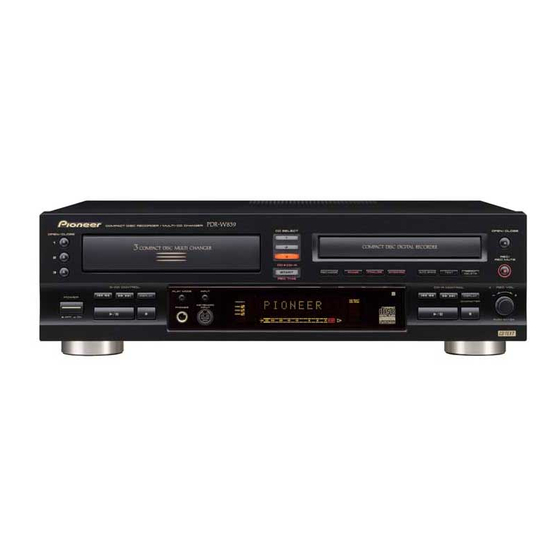
COMPACT DISC RECORDER / MULTI-CD CHANGER
PDR-W839
THIS MANUAL IS APPLICABLE TO THE FOLLOWING MODEL(S) AND TYPE(S).
Model
Type
PDR-W839
KUXJ/CA
WYXJ
WVXJ
[ EXPLANATORY NOTE ]
• After reparing the unit, make sure to return the opera-
tion condition to the shipping position. (for protection
during packing)
Refer to P.81 "Setting the initial condition for shippping".
CONTENTS
1. SAFETY INFORMATION .......................................... 2
2. EXPLODED VIEWS AND PARTS LIST .................... 4
4. PCB CONNECTION DIAGRAM .............................. 44
5. PCB PARTS LIST ................................................... 58
6. ADJUSTMENT ........................................................ 63
7. GENERAL INFORMATION ..................................... 77
7.1 DIAGNOSIS ...................................................... 77
7.1.1 ERROR CODE ............................................ 77
7.1.2 SOLUTION OF 3CD TRAY MISMATCHING ...... 78
PIONEER CORPORATION
PIONEER ELECTRONICS SERVICE, INC. P.O. Box 1760, Long Beach, CA 90801-1760, U.S.A.
PIONEER EUROPE NV Haven 1087, Keetberglaan 1, 9120 Melsele, Belgium
PIONEER ELECTRONICS ASIACENTRE PTE. LTD. 253 Alexandra Road, #04-01, Singapore 159936
c
PIONEER CORPORATION 2000
OPEN/CLOSE
0
1
2
0
3
0
POWER
— OFF _ ON
Power Requirement
AC120V
AC220-240V
AC220-240V
4-1, Meguro 1-chome, Meguro-ku, Tokyo 153-8654, Japan
◊ÛB¿ˆ˘≤/
COMPACT DISC RECORDER / MULTI-CD CHANGER
CD SELECT
1
3
- COMPACT DISC MULTI CHANGER
2
COMPACT DISC DIGITAL RECORDER
3
CD=CD-R
START
REC MODE
ERASE
FINALISE
SYNCHRO
REC THIS
3-CD CONTROL
PLAY MODE
INPUT
4 1
¡ ¢
KEYBOARD
PHONE
INPUT
6
7
FOR U.S. MODELS
NECESSARY INFORMATION FOR DHHS
RULES MARKED ON THE REAR BASE AND ON
THE TOP OF CD MECHANISM AS BELOW.
DANGER – LASER RADIATION WHEN OPEN.
AVOID DIRECT EXPOSURE TO BEAM.
7.1.3 POWER ON SEQUENCE ......................... 79
7.1.4 ERROR MESSAGE "CHECK TEMP" ....... 82
7.1.5 CD-R DISC MANUFACTURER CODE ........ 82
7.1.6 DISASSEMBLY ........................................ 83
7.1.7 DIAGNOSIS OF MAIN ASSY ................... 87
7.1.8 DIAGNOSIS OF CD-R CORE ASSY ........ 87
7.2 PARTS ........................................................... 88
7.2.1 IC ............................................................. 88
7.2.2 DISPLAY ................................................ 102
8. PANEL FACILITIES AND SPECIFICATIONS ..... 104
OPEN/CLOSE
0
REC/
REC MUTE
MENU
AUTO SPACE
NAME
DELETE
COPY CONTROL
REC VOL
4 1
¡ ¢
DISPLAY
CHARACTER
ORDER NO.
6
7
PUSH ENTER
CD TEXT
Legato Link Conversion
RRV2352
Remarks
T – ZZV AUG. 2000 Printed in Japan
Advertisement
Table of Contents

Related Manuals for Pioneer PDR-W839


Summary of Contents for Pioneer PDR-W839
- Page 1 PIONEER CORPORATION 4-1, Meguro 1-chome, Meguro-ku, Tokyo 153-8654, Japan PIONEER ELECTRONICS SERVICE, INC. P.O. Box 1760, Long Beach, CA 90801-1760, U.S.A. PIONEER EUROPE NV Haven 1087, Keetberglaan 1, 9120 Melsele, Belgium PIONEER ELECTRONICS ASIACENTRE PTE. LTD. 253 Alexandra Road, #04-01, Singapore 159936 PIONEER CORPORATION 2000 T –...
-
Page 2: Safety Information
The use of a substitute replacement component which does Leakage 0.5mA current Device not have the same safety characteristics as the PIONEER tester under recommended replacement one, shown in the parts list in test this Service Manual, may create shock, fire, or other hazards. - Page 3 PDR-W839 CD RECORDER CD PLAYER IMPORTANT IMPORTANT THIS PIONEER APPARATUS CONTAINS THIS PIONEER APPARATUS CONTAINS LASER OF CLASS ΙΙΙ b. LASER OF CLASS 1. SERVICING OPERATION OF THE APPARATUS SERVICING OPERATION OF THE APPARATUS S H O U L D B E D O N E B Y A S P E C I A L L Y S H O U L D B E D O N E B Y A S P E C I A L L Y INSTRUTED PERSON.
-
Page 4: Exploded Views And Parts List
15 (1/2) Keypad Stickers See Contrast table (2) Caution See Contrast table (2) (2) CONTRAST TABLE PDR-W839/KUXJ/CA, WYXJ and WVXJ Types are constructed the same except for the following : Part No. Mark No. Symbol and Description Remarks KUXJ/CA Type... - Page 5 PDR-W839 2.2 EXTERIOR SECTION KUXJ/CA Type Only KUXJ/CA Type Only Refer to "2.4 CD-R CORE (Mechanism) ASSY (1/2)". Refer to "2.6 3CD MICROCHANGER MECHANISM". KUXJ/CA Type Only WYXJ and WVXJ Types Only 36 or 37 (WYXJ Type Only) Refer to...
- Page 6 See Contrast table (2) Screw IBZ30P180FMC Power Button B PAC2009 Screw FBT40P080FZK (2) CONTRAST TABLE PDR-W839/KUXJ/CA, WYXJ and WVXJ Types are constructed the same except for the following : Part No. Mark No. Symbol and Description Remarks KUXJ/CA Type WYXJ Type WVXJ Type...
- Page 7 PPZ30P080FZK Screw ABA7009 O/C Button PAC1982 Random Button PAC1996 (2) CONTRAST TABLE PDR-W839/KUXJ/CA, WYXJ and WVXJ Types are constructed the same except for the following : Part No. Mark No. Symbol and Description Remarks KUXJ/CA Type WYXJ Type WVXJ Type...
- Page 8 PDR-W839 2.4 CD-R CORE (Mechanism) ASSY (1/2) • Bottom View Refer to "2.5 CD-R CORE ASSY (2/2)". CD-R CORE CN101 • CD-R CORE (Mechanism) ASSY(1/2) PARTS LIST Mark No. Description Part No. Mark No. Description Part No. 1 LOAB Assy...
- Page 9 PDR-W839 2.5 CD-R CORE (Mechanism) ASSY (2/2) • CD-R CORE (Mechanism) ASSY(2/2) PARTS LIST Mark No. Description Part No. MECHA PCB Assy PWX1625 DC Motor (SPINDLE) PXM1044 DC Motor (CARRIAGE) PXM1045 Float Rubber PEB1308 Carriage Motor Assy PEA1353 Rack Spring...
- Page 10 PDR-W839 2.6 3CD MICROCHANGER MECHANISM *1 : Floil (GYA1001) *2 : Dyefree (GEM1003) (Gutter) (No.36 Sub Tray Part) (Bottom Gutter) (Inside Gutter) (Gutter) (Left Front Under Gutter) (Bottom Gutter) (Boss) (Gutter) (Whole) (Gutter) (Black) (Gutter) (Blue) (Shaft) (Rail) (Gutter) (Column)
- Page 11 PDR-W839 • 3CD MICROCHANGER MECHANISM PARTS LIST Mark No. Description Part No. MOTOR Unit AWU7431 LOADING Unit AWU7432 SELECT Unit AWU7433 PICKUP Unit KSM213CCM Carriage Motor VXM1033 Mechanism Base ANW7129 Motor Pulley PNW1634 Lift Spring ABH7173 Home Lever ANW7153 HL Spring 2...
-
Page 12: Block Diagram And Schematic Diagram
PDR-W839 3. BLOCK DIAGRAM AND SCHEMATIC DIAGRAM 3.1 BLOCK DIAGRAM AWU7431 E F G AWU7432 AWU7433 3CD MECHA. Ass’y CD PICKUP unit KSM213CCM N1101 RFGO IC1101 CN902 CN1201 TA2150FN A – F RF AMP PickUp IC1201 DOUT TC9495F IC1301 F+/-... - Page 13 PDR-W839 CDR CORE ASSY CN901 : 3CD PLAY : CD-R PLAY CN202 CN1101 CN201 POWER SUPPLY UNIT V+8A V+16A PWR1029 AC IN V–16A V+5K V+6M V+5D VF–24 IC801 AOUTL + / – 25 26 IC803 NJM2121M LINE IN A K4524VF...
-
Page 14: Overall Wiring Diagram
PDR-W839 3.2 OVERALL WIRING DIAGRAM POWER SUPPLY UNIT (PWR1029) PG06KK-F20 PDD1218 GNDS GNDA GNDA FPDO V+5A V+5A CFREQ CMOD PGND CDR CORE ASSY VRDC VWDC2 (PYY1286) VWDC1 GNDD OSCEN ODON W/XR LDON PDD1217... - Page 15 PDR-W839 Note : When ordering service parts, be sure to refer to "EXPLODED VIEWS and PARTS LIST" or "PCB PARTS LIST". 3CD MICRO CHANGER MECHANISM ASSY (AXA7096) PDD1215 PICKUP UNIT (KSM213CCM) 1/3- MAIN ASSY CN101 CN1302 (KUXJ/CA : PWM2325) J102...
- Page 16 PDR-W839 3.3 CD-R CORE ASSY(1/5) CD-R CORE ASSY (PYY1286) Regulator...
- Page 17 PDR-W839 Mecha. Control U-com : The power supply is shown with the marked box. CN302 CN904...
- Page 18 PDR-W839 3.4 CD-R CORE ASSY(2/5) 2 /5 CD-R CORE ASSY (PYY1286) CN101...
- Page 19 PDR-W839 RF PROCESSOR F Rank : 1% F Rank : 1% SIGNAL ROUTE CN102 : RF SIGNAL (OP) : OPTICAL SIGNAL (CO) TP_POINT : COAXI AL SIGNAL : AUDIO SIGNAL (DIGITAL) : AUDIO SIGNAL (REC)
- Page 20 PDR-W839 3.5 CD-R CORE ASSY(3/5) CD-R CORE ASSY (PYY1286)
- Page 21 PDR-W839 Multiplexer Servo Amp IC...
- Page 22 PDR-W839 3.6 CD-R CORE ASSY(4/5) (CO) (OP) EFM ENCODER...
- Page 23 PDR-W839 CD-R CORE ASSY (PYY1286) CN502 (CO) (OP) SIGNAL ROUTE : AUDIO SIGNAL (REC) : AUDIO SIGNAL (DIGITAL)
- Page 24 PDR-W839 3.7 CD-R CORE ASSY(5/5),MECHA PCB ASSY and LOAB ASSY CD-R CORE ASSY (PYY1286) 5CH BTL Driver LOADING MOTOR PXM1017 CN453 VKP2253 CN451 CN452 F Rank (1%) CN101 S101 LOAB ASSY (VWG2171) MECHA PCB ASSY DC MOTOR ASSY (SPINDLE) CN601...
- Page 25 PDR-W839 F rank (1%) CN901 (GND reinforcement for radiation measures) CN202 SIGNAL ROUTE : RF SIGNAL : AUDIO SIGNAL (DIGITAL) : The power supply is shown with the marked box.
- Page 26 PDR-W839 VOLTAGES and WAVEFORMS Signal Logic Note : The encircled numbers denote measuring point in the schematic • Spindle System diagram. CD-R CORE ASSY CD-R CORE ASSY SPLG1 SPLG3 CN302 - pin 1 (MSI) IC301 - pin 21 (CLOCKDEC) Media Pickup Position V: 200mV/div.
- Page 27 PDR-W839 CD-R CORE ASSY CD-R CORE ASSY CD-R CORE ASSY CN101 - pin 29 (F+) CN102-pin 8 (FE) IC501 - pin 37 (REWLDON) CN452 - pin 4 (SL+) V: 200mV/div. , H: 20µsec/div. V: 20mV/div. , H: 2msec/div. V: 200mV/div. , H: 1msec/div.
- Page 28 PDR-W839 3.8 MOTOR, LOADING, SELECT and PICKUP UNITS SELECT UNIT : FOCUS SERVO LOOP LINE : TRACKING SERVO LOOP LINE (AWU7433) : SPINDLE SERVO LOOP LINE : CARRIAGE SERVO LOOP LINE : LOADING SERVO LOOP LINE MOTOR UNIT (AWU7431) CN101...
- Page 29 PDR-W839 3CD CORE ASSY IC1101 - pin 25 (RFGO) CN1201 - pin 12 (BUS0) V: 50mV/div., H: 500nsec/div. V: 200mV/div., H: 1msec/div. (PLAY) (PLAY) IC1201 - pin 55 (DMO) CN1201 - pin 13 (BUS1) V: 200mV/div., H: 5µsec/div. V: 200mV/div., H: 1msec/div.
- Page 30 PDR-W839 3.9 3CD CORE ASSY 3CD CORE ASSY (PWM2334) 5CH BTL Driver H : Normal Speed L : Double Speed STBY CN1302 CN1301 CN1101...
- Page 31 PDR-W839 CN1201 Digital Servo IC 9607S-33F Details and substitution are done by the part list. SIGNAL ROUTE : RF SIGNAL : AUDIO SIGNAL(DIGITAL)
- Page 32 PDR-W839 3.10 MAIN ASSY(1/3) C1128 COPY Codec IC CH 100P EXCEPT KU (at L853)
- Page 33 PDR-W839 MAIN ASSY(1/3) (KUXJ/CA :PWM2325 ,WYXJ,WVXJ :PWM2326) From IC803 IC810(2/2) MBA FILM CQMBA IC810(1/2) EXCEPT KU R473 BA4560F CN801 BA4560F KU type EXCEPT KU type SIGNAL ROUTE C455 STBY CH 100P C456 : AUDIO SIGNAL(DIGITAL) C1127 100P 470P : AUDIO SIGNAL(ANALOG)
- Page 34 PDR-W839 3.11 MAIN ASSY(2/3) MAIN ASSY(2/3) (KUXJ/CA :PWM2325 ,WYXJ,WVXJ :PWM2326) CN1101 CN201 R9631 CN502 CN601...
- Page 35 PDR-W839 : The power supply is shown with the marked box. (at L605) (at L608) YF Ceramic CKSRYF SIGNAL ROUTE : AUDIO SIGNAL (DIGITAL)
- Page 36 PDR-W839 3.12 MAIN ASSY(3/3) MAIN ASSY (KUXJ/CA :PWM2325 ,WYXJ,WVXJ :PWM2326) KU type EXCEPT KU type C903 CH 22P STBY C905 PCB Binder VEF1040 System Control 16MHz U-com KU type EXCEPT KU type L809 (R9809) DTL1058 L810 (R9810) KU type EXCEPT KU type...
- Page 37 PDR-W839 CN701 SXMUTE DITOUT XOPT CN902 CN302 SIGNAL ROUTE TYPES FUNCTION : AUDIO SIGNAL (DIGITAL) TWO OPTICAL DIGITAL INPUTS RENTAL COPY LEGATO LINK CONVERSION HI-BIT DEMO INDICATION AVAILABLE FOR JAPANESE KEYBOARD...
- Page 38 PDR-W839 MAIN ASSY MAIN ASSY CN901 - pin 21 (FLCL) CN601 - pin 1 (AUXTX) CN601 - pin 10 (DACLRCK) CN601 - pin 15 (DADI) V: 200mV/div., H: 10msec/div. V: 200mV/div., H: 200nsec/div. V: 200mV/div., H: 10µsec/div. V: 200mV/div., H: 5msec/div.
- Page 39 PDR-W839...
- Page 40 PDR-W839 3.13 HEAD PHONE, OPERATING1, OPERATING2 and OPERATING3 ASSYS HEADPHONE ASSY CN801 (KUXJ/CA : PWZ4157) (WYXJ/WVXJ : PWZ4158) CN1301 J1301 JA1301 To *A Display IC FL Indicator Tube OPERATING 1 ASSY (KUXJ/CA : PWZ4133) (WYXJ/WVXJ : PWZ4134)
- Page 41 PDR-W839 HEADPHONE ASSY CN902 (KUXJ/CA : PWZ4157) (WYXJ/WVXJ : PWZ4158) CN701 To *A JA1361 J1360 To KEY BOARD CN702 KU ONLY J703 C734 OPERATING 2 ASSY (KUXJ/CA : PWZ4141) (WYXJ/WVXJ : PWZ4142) OPERATING 2 ASSY S704 : 7 STOP S705 : DISP J705 S706 : ¡¢...
- Page 42 PDR-W839 4.13 POWER SUPPLY ASSY POWER SUPPLY UNIT (PWR1029) CAUTION : FOR CONTINUED PROTECTION AGAINST RISK OF FIRE. REPLACE WITH SAME TYPE NO. 215002 MFD. BY LITTELFUSE INC. FOR FU1 (215002). • NOTE FOR FUSE REPLACEMENT FOR CONTINUED PROTECTION AGAINST RISK OF FIRE.
- Page 43 PDR-W839 GNDA1 V+8A V+16A GNDA2 V–16A V+5K GNDM V+6M CN1101 GNDD V+5D GNDFL VF–24 FL AC A FL AC B V+5A GNDA V+5D GNDD CN901 V+6P Service Parts GNDP Part No. 215002 (2A) CAUTION : FOR CONTINUED PROTECTION AGAINST RISK OF FIRE.
-
Page 44: Pcb Connection Diagram
PDR-W839 4. PCB CONNECTION DIAGRAM NOTE FOR PCB DIAGRAMS : 1. Part numbers in PCB diagrams match those in the schematic 3. The parts mounted on this PCB include all necessary parts for diagrams. several destinations. 2. A comparison between the main parts of PCB and schematic For further information for respective destinations, be sure to diagrams is shown below. - Page 45 PDR-W839 4.2 MECHA PCB ASSY and LOAB ASSY LOAB ASSY (VNP1762-A) CN451 MECHA PCB ASSY MECHA PCB ASSY CARRIAGE MOTOR SPINDLE MOTOR CN452 (PNP1476-A) (PNP1476-A) SIDE A SIDE B...
- Page 46 PDR-W839 4.3 CD-R CORE ASSY CDR CORE ASSY SIDE A (PNP1477-B) IC307 IC308 Q205 IC507 IC1161 IC306 IC305 IC201 IC506 IC303 IC309 IC931 IC502 IC505 IC504 IC255 IC302 IC107 IC304 IC421 IC422 IC401 Q101 Q104 IC102 Q103 IC103...
- Page 47 PDR-W839 CDR CORE ASSY SIDE B To POWER SUPPLY CN601 CN601 ASSY CN904 To CDR PICKUP CN101 (PNP1477-B) IC503 Q502 Q273 IC501 Q202 Q201 IC301 IC207 IC206 Q402 IC251 IC253 IC310 Q401 IC252 IC254 IC101 IC451...
- Page 48 PDR-W839 4.4 3CD CORE ASSY To PICKUP CN101 UNIT 3CD CORE ASSY SIDE A CN902 To PICKUP UNIT (ANP7532-D)
- Page 49 PDR-W839 3CD CORE ASSY SIDE B IC1201 Q1201 IC1101 IC1302 Q1101 IC1301 IC1102 Q1301 (ANP7532-D)
- Page 50 PDR-W839 4.5 MAIN ASSY MAIN ASSY To POWER SUPPLY ASSY CN1201 CN701 CN1301...
- Page 51 PDR-W839 SIDE A CN302 (PNP1480-C) CN502...
- Page 52 PDR-W839 MAIN ASSY (PNP1480-C) IC802 IC801 Q801 Q405 Q483 Q401 Q402 Q404 Q484 Q492 IC1811 IC803 Q403 IC810 IC402 IC401 Q480 Q601 Q490 Q481 IC903 IC904 IC90...
- Page 53 PDR-W839 SIDE B IC601 Q492 IC1811 Q401 Q428 Q490 Q481 IC901...
- Page 54 PDR-W839 4.6 HEAD PHONE, OPERATING1, OPERATING2 and OPERATING3 ASSY OPERATING3 ASSY OPERATING2 ASSY (PNP1481-A) SIDE A I J K...
- Page 55 PDR-W839 HEAD PHONE ASSY CN801 To Key Board OPERATING1 ASSY CN901...
- Page 56 PDR-W839 HEAD PHONE ASSY OPERATING1 ASSY Q708 IC701...
- Page 57 PDR-W839 OPERATING3 ASSY OPERATING2 ASSY (PNP1481-A) SIDE B IC701 Q701–Q704 Q705 Q707 Q706 I J K...
-
Page 58: Pcb Parts List
PDR-W839 5. PCB PARTS LIST • NOTES: Parts marked by "NSP" are generally unavailable because they are not in our Master Spare Parts List. • Mark No. Description Part No. Mark No. Description Part No. mark found on some component parts indicates the importance of the safety factor of the part. - Page 59 PDR-W839 Mark No. Description Part No. Mark No. Description Part No. Part No. Mark Remarks Symbol & Description PWM2325 PWM2326 R966,R967,R969-R971 RS1/16S221J RS1/16S101J R427,R428 RS1/16S472J RS1/16S182J R425,R426 RS1/16S472J Not used R945 Not used RS1/16S103J R951 RS1/16S103J Not used R421,R422 Not used...
- Page 60 PDR-W839 Mark No. Description Part No. Mark No. Description Part No. C212,C451 CKSRYB272K50 RESISTORS C113,C205 CKSRYB333K16 Other Resistors RD1/4PU C480,C481 CKSRYB471K50 C124 CKSRYB472K50 C102,C206,C413 CKSRYB473K16 OTHERS J601 3P Jumper Wire D20PWW0305E C132 CKSRYB563K16 C204,C408,C468,C469 CKSRYB681K50 C125,C463,C464 CKSRYB682K50 LOAB ASSY C416,C905...
- Page 61 PDR-W839 Mark No. Description Part No. Mark No. Description Part No. R1317 RS1/10S2702F D904 DAP202K Other Resistors RS1/10S D1102,D1103 RB501V-40 OTHERS COILS AND FILTERS CN1201 33P FFC Connector 9607S-33F X901 ASS7020 CN1301 KR Connector S6B-PH-K-S L601,L602,L610,L809,L810 DTL1058 CN1101 FFC Connector...
- Page 62 PDR-W839 Mark No. Description Part No. Mark No. Description Part No. JA603 Optical Link In GP1FA550RZ RESISTORS JA604 Optical Link Out GP1FA550TZ Other Resistors RS1/16S JA605 1P Jack PKB1028 JA606 1P Jack PKB1033 OTHERS JA601 Remote Control Jack PKN1004 3P Cable Holder...
-
Page 63: Adjustment
PDR-W839 DANGER – LASER RADIATION WHEN OPEN. 6. ADJUSTMENT AVOID DIRECT EXPOSURE TO BEAM. CD CHECK NOTE: There is no information to be shown in this 3CD adjustment. Slider Gear 6.1 3CD SLIDER OPERATION CONFIRMATION (1) Eject the disc ,and when all 3CD tray stay at the home position, turn off the power. - Page 64 PDR-W839 CD-R ADJUSTMENT 6.3 DISCS TO BE USED • SERVO SYSTEM ADJUSTMENT CD: Test disc for adjustment (STD-903) or equivalent Test disc for inspection (STD-914) or equivalent 6.4 MEASURING INSTRUMENTS (1) Laser power meter Following power meter manufactured by Advantest Corporation or equivalent:...
-
Page 65: Test Mode
PDR-W839 6.6 TEST MODE 6.6.1 How to Enter the Test Mode TEST MODE : ON Display Power key -ON NAME key DISPLAY key POWER DISPLAY NAME state Pressing both the 3CD DISPLAY key Continue pressing both the DISPLAY key and and NAME key,turn ON the POWER. - Page 66 PDR-W839 6.6.3 OPERATIONS IN TEST MODE ◊ÛB¿ˆ˘≤/ COMPACT DISC RECORDER / MULTI-CD CHANGER CD SELECT OPEN/CLOSE OPEN/CLOSE - COMPACT DISC MULTI CHANGER COMPACT DISC DIGITAL RECORDER REC/ REC MUTE CD=CD-R ¶ MENU START ERASE FINALISE SYNCHRO REC MODE AUTO SPACE...
- Page 67 PDR-W839 DANGER – LASER RADIATION WHEN OPEN. 6.7 LD POWER ADJUSTMENT AVOID DIRECT EXPOSURE TO BEAM. 6.7.1 Playback Power Adjustment Pickup objective lens Test Point 0.9 mW ± 0.05 mW Adjustment Value Purpose Optimizing playback power of laser diode. Incapable of disc discrimination, playback, or track searches. Or track skipping.
- Page 68 PDR-W839 DANGER – LASER RADIATION WHEN OPEN. AVOID DIRECT EXPOSURE TO BEAM. 6.7.3 CD-RW Record Power Adjustment Test Point Pickup objective lens RW Bias : 2.3 mW ± 0.05 mW, RW Rec : 3.2 mW ± 0.05 mW, RW Erase : 5.2 mW ± 0.1 mW...
- Page 69 PDR-W839 6.8 SERVO ADJUSTMENT MANUAL ADJUSTMENT 6.8.1 Preparations 1. Enter the TEST mode. 2. Press the INPUT key so that "OPTICAL" appears on the FL display. 3. Press the ERASE key more than three seconds to initialize it. 4. Press the SYNCHRO key to perform the average process.
- Page 70 PDR-W839 6.8.4 RFOM Offset Adjustment Test Point CN102-pin 2 (RF) 0 mV ± 30 mV Adjustment Value Purpose Optimizing DC offset voltage of RFDC output circuit when playing back. Symptom when Out of Adjustment Focus-in does not function, incapable of searching, or track skipping.
- Page 71 PDR-W839 6.8.6 SPP Offset Adjustment Test Point CN102-pin 3 (MPX) 0 mV ± 50 mV Adjustment Value Purpose Optimizing DC offset voltage of sub-signal output circuit. Symptom when Out of Adjustment Playback does not function, incapable of searching, or track skipping.
- Page 72 PDR-W839 6.8.8 MPP Offset Readjustment Test Point CN102-pin 5 (Tracking err) 0 mV ± 50 mV Adjustment Value Purpose Optimizing DC offset voltage of tracking-error output circuit. Symptom when Out of Adjustment Playback does not function, incapable of searching, or track skipping.
- Page 73 PDR-W839 6.8.9 Focus Bias Adjustment Test Point CN102-pin 2 (RF) Adjustment Value Minimize jitter value Purpose Optimizing DC offset voltage of focus servo loop circuit including pickup. Focus-in does not function, sound pauses, bad RF wave form, or incapable of Symptom when Out of Adjustment playing some discs.
- Page 74 PDR-W839 AUTOMATIC ADJUSTMENT 6.8.10 Preparation CN102-pin 3 (MPX) Test Point Discs to be Used CD test disc (STD-903) FL Indication Method [Procedure] 1. Press the INPUT key so that "OPTICAL" appears on the FL display. \ If it was not displayed the Focus Offset Adjustment, press the AUTO SPACE key and shift to the Focus Offset Adjustment.
- Page 75 PDR-W839 6.8.13 Focus Bias Adjustment Test Point CN102-pin 2 (RF) Adjustment Value Minimize jitter value Optimizing DC offset voltage of focus servo loop circuit including pickup. Purpose Focus-in does not function, sound pauses, bad RF wave form, or incapable of Symptom when Out of Adjustment playing some discs.
- Page 76 PDR-W839 <Pickup replacement repair, the final check inspection method after adjustment> Disk required: CD-R disc * [STD-R07(PVC:RDD-74B,RDD-74BJ)] [STD-R08(PVC:RDD-74,RDD-74U)] or equivalent CD-RW disc * [STD-R11(PVC:RDW-74,RDW-74J)] or equivalent [Inspection items] 1. Recording-playback jitter Method: Measure RF signal (CN102-pin2) by Jitter Meter (Trailing edge).
-
Page 77: General Information
7.1.1 ERROR CODE (CD-R) Error Code Display for Service The PDR-W839 can display the error codes for service. When the DISPLAY key of the CD-R side and ERASE key is held down simultaneously, an FL display as shown below is... -
Page 78: Solution Of 3Cd Tray Mismatching
PDR-W839 Error code table for service Code Generation Condition In the tray opening procedure, if opening is not completed within 4.5 sec., the procedure moves to closing. Afterwards if this closing is not completed within 4.5 sec., the procedure recalls opening again. -
Page 79: Power On Sequence
PDR-W839 7.1.3 POWER ON SEQUENCE POWER ON SEQUENCE (Display System) Check Point POWER ON • Blow out fuse (FU01) of the primary side on the POWER SUPPLY Assy • Blow out micro-fuse (IC02,IC03) on the POWER SUPPLY Assy • System controller (IC901) on the MAIN Assy breaks down When FL does not turn on at all: •... - Page 80 PDR-W839 SETUP SEQUENCE (3CD) POWER ON FL display the time 0f 3CD DISC on the STOP Any tray failing clamped tary? (Clamping the tray) TOC READ? Start the timer Clamp the tray failing TOC READ PLAY (Doing TOC READ) About 15sec.
- Page 81 PDR-W839 Initialization Sequence at POWER ON of 3CD MICRO CHANGER MECHANISM POWER ON MECHA SW • SELINIT SW (pin 4) • SEL SW (pin 5) Each mechanism SW is checked. • OPEN SW (pin 90) • CLOSE SW (pin 91) •...
-
Page 82: Cd-R Disc Manufacturer Code
7.1.5 CD-R DISC MANUFACTURER CODE PDR-W839 has a function to check the "Manufacturer Code" of a CD-R disk. By checking the information in the "Lead-in Start Time", which is displayed when the following procedure is performed, against the following table, the manufacturer becomes clear. -
Page 83: Disassembly
PDR-W839 7.1.6 DISASSEMBLY Servo Mechanism Block Bonnet Tray Open (Changer section) (Recorder section) POWER OPEN/CLOSE OPEN/CLOSE Bridge Drive Gear Front ×3 ×2 Bonnet Tray Unhook ×2 CD-R CORE Assy CN453 CN452 Remove four Tray Panel C connectors. ×2 Tray Panel R... - Page 84 PDR-W839 3CD MICROCHANGER MECHANISM • Bottom view ×2 CN902 Remove four connectors. CN101 ×4 CN1201 ×2 CN1301 CN1302 CD CORE PCB Assy 3CD Microchanger Mechanism ×2 3CD Mechanism Base F • Top view SUB Tray (x 3) Hook (x2) is removed and the elevator,...
- Page 85 PDR-W839 Clamper Holder Float Base Main Tray Bottom View The Hook is removed. Black ( The bottom of a main Blue tray is lifted.) Swing Base Hook PICKUP UNIT Hook take off Mecha Base...
- Page 86 PDR-W839 Attention when 3CD MICROCHANGER MECHA is assembied Tray installation Not to be caught to the tray when the tray is put, the home lever is opened. The stopper arm is shut. Gear match of sub-tray The stick of Ø3 (plus driver etc.of #0) is...
-
Page 87: Diagnosis Of Cd-R Core Assy
PDR-W839 7.1.7 DIAGNOSIS OF 3CD MICROCHANGER MECHANISM and MAINASSY When diagnosing the 3CD Microchanger Mechanism and MAIN Assy, use the following Flexible Cables and Connector Assy for service. (When you diagnose only 3CD Microchanger Mechanism, the product operates with CD-R CORE ASSY removed. ) Remove the CD-R CORE Assy. -
Page 88: Parts
PDR-W839 7.2 PARTS • The information shown in the list is basic information and may not correspond exactly to that shown in the schematic diagrams. 7.2.1 IC • List of IC PE5190B, AK8567, BA5810FP, PDC069, PD5603A PE5190B (CD-R CORE ASSY : IC301) •... - Page 89 PDR-W839 • Pin Function(2/2) n i l − GNDD − GNDD c t i EFM playback RF detection t (L : Focus OK) c t i L " ) " − Playback Playback n i l L " ) "...
- Page 90 PDR-W839 AK8567 (CD-R CORE ASSY : IC101) • RF Processor • Pin Function(1/3) v i t source pin ß ß External capacitor connector pin for PHBETA droop rate setting External capacitor connector pin for PHBETA droop rate setting n push-pull signal output pin...
- Page 91 PDR-W839 • Pin Function(2/3) ded area detection signal output pin2 ("H" recorded, "L" unrecorded) Recorded area detection signal output pin1 ("H" recorded, "L" unrecorded) t pin t pin t pin1 (input sine wave ) pin2 (input sine wave ) i g i...
- Page 92 PDR-W839 • Pin Function(3/3) t f i pin for signal monitoring pin for Recorded area detection Read RF signal output pin Write RF signal output pin t pin t pin t pin t pin t pin t pin t pin...
- Page 93 PDR-W839 BA5810FP (CD-R CORE ASSY : IC451) • 5Channel Driver IC • Block Diagram CH1~ POWVCC 34 (CH3, CH4) MUTE 7.5k LEVEL 7.5k SHIFT LEVEL SHIFT LEVEL LOADING PRE SHIFT FWD REV LEVEL 7.5k SHIFT 7.5k POWER PREVCC POWVCC 12...
- Page 94 PDR-W839 PDC069 (CD-R CORE ASSY : IC501) • Encoder IC • Pin Function(1/5)
- Page 95 PDR-W839 • Pin Function(2/5)
- Page 96 PDR-W839 • Pin Function(3/5)
- Page 97 PDR-W839 • Pin Function(4/5)
- Page 98 PDR-W839 • Pin Function(5/5)
- Page 99 PDR-W839 PD5603A (MAIN ASSY : IC901) • System Control IC • Pin Function l a i SELI- 3CD Mecha select drive control 3CD Mecha SW(Initail Select position detect) SELINIT SELECT 3CD Mecha SW(Select position detect) CLAMP 3CD Mecha SW(CLAMP END detect)
- Page 100 PDR-W839 EPM(at FLASH) t i r EEPCLK Clock output for EEPROM Data output for EEPROM EEPDATA Simultaneous recording ON/OFF SW URAROKU CE(at FLASH) t i r Not used (L outputs) Not used (L outputs) Internal/External input OP amp change SW...
- Page 101 PDR-W839 XCDCE CD chip enable output CDBUCK CD Bus clock output CDBUS0 CDBUS1 CD Bus clock output CDBUS2 CDBUS3 LOADIN 3CD mechanism loading drive control LOADOUT 3CD mechanism SW (PU most inner side) (L:PU most inner side) CDINSIDE 3CD mechanism SW (L: CD tray open end)
-
Page 102: Display
PDR-W839 7.2.2 DISPLAY PEL1102 (OPERATING 1 ASSY : V701) • FL Display External Dimensions Pin Assignment Anode and Grid Assignment... - Page 103 PDR-W839...
-
Page 104: Panel Facilities
PDR-W839 8. PANEL FACILITIES AND SPECIFICATIONS 8.1 PANEL FACILITIES Front Panel ◊ÛB¿ˆ˘≤/ COMPACT DISC RECORDER / MULTI-CD CHANGER CD SELECT OPEN/CLOSE OPEN/CLOSE COMPACT DISC DIGITAL RECORDER - COMPACT DISC MULTI CHANGER REC/ REC MUTE CD=CD-R ¶ MENU START REC MODE... -
Page 105: Remote Control Unit
PDR-W839 Remote Control Unit DISPLAY/CHARA – Press to switch between display modes, and between upper-and lower-case characters while using CD text. SCROLL – Press to scroll through long names in CD text. MENU/DELETE – Press to access the preference menu options. Press to delete characters while edting CD text. - Page 106 PDR-W839 Display CD TEXT DISC# DISC TOTAL STEP REMAIN STEP TRACK# CD-RW ARTST# FINALIZE MANUAL DISC TRACK DISC SYNC-1 SINGLE ALL RELAY FADER SCAN RPT- 1 SKIP ON VOL FIX DIG DISC PARTIAL A.SPACE ANALOG REC THIS OVER –dB OPTICAL...
-
Page 107: Specifications
PDR-W839 8.2 SPECIFICATIONS 1. General 3. Input jacks Model ......Compact disc audio system Optical digital input jack Applicable discs ....CDs, CD-Rs and CD-RWs Coaxial digital input jack Power supply ........AC 120 V, 60 Hz Audio LINE input jacks (U.S./Canadian models)