Table of Contents
Advertisement
Available languages
Available languages
Owner's Manual
1/3 HP
1/2 HP
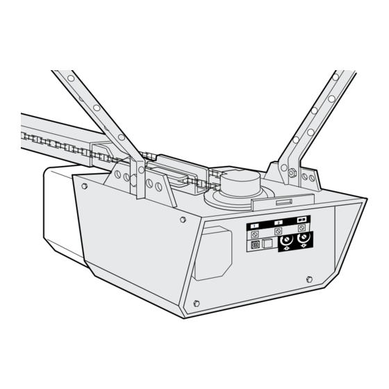
GARAGE DOOR OPENER
For Residential Use Only
Models:
139.18054 • 139.18056 • 139.18654 • 139.18656
139.18673 • 139.18674 • 139.18973 • 139.18974
CAUTION:
Read and follow all safety rules
and operating instructions before
first use of this product.
Fasten the manual near the garage
door after installation.
®
Sears Canada, Inc., Toronto, Ontario M5B 2B8
www.sears.com/craftsman
MD
Safety Precautions
I
Assembly
I
Installation
I
Adjustment
I
Maintenance
I
Operation
I
Troubleshooting
I
Parts List
I
Advertisement
Chapters
Table of Contents

Related Manuals for Craftsman 139.18054


Summary of Contents for Craftsman 139.18054
- Page 1 Owner’s Manual 1/3 HP 1/2 HP GARAGE DOOR OPENER For Residential Use Only Models: 139.18054 • 139.18056 • 139.18654 • 139.18656 139.18673 • 139.18674 • 139.18973 • 139.18974 Safety Precautions CAUTION: Read and follow all safety rules Assembly and operating instructions before Installation first use of this product.
-
Page 2: Table Of Contents
TABLE OF CONTENTS Introduction Adjustment 28-30 Safety symbol and signal word review ......2 Adjust the travel limits ..........28 Preparing your garage door ........3 Adjust the force ............29 Tools needed ...............3 Test the safety reversal system .........30 Planning ..............4-5 Test the safety reversing sensor........30 Carton inventory............6 Operation 31-34... -
Page 3: Preparing Your Garage Door
Preparing your garage door WARNING Before you begin: To prevent possible SERIOUS INJURY OR DEATH: • Disable locks. • ALWAYS call a trained door systems technician if CAUTION • Remove any ropes connected to garage door. garage door binds, sticks, or is out of balance. An unbalanced garage door may not reverse when •... -
Page 4: Planning
Planning • Do you have an access door in addition to the garage door? If not, Model 18752 Emergency Key Identify the type and height of your garage door. Release is required. See Accessories page. Survey your garage area to see if any of the •... - Page 5 Planning (continued) WARNING ONE-PIECE DOOR INSTALLATIONS Without a properly working safety reversal system, persons (particularly small children) could be • Generally, a one-piece door does not require CAUTION SERIOUSLY INJURED or KILLED by a closing reinforcement. If your door is lightweight, refer to garage door.
-
Page 6: Carton Inventory
Carton Inventory Your garage door opener is packaged in two cartons which contains the motor unit and the parts illustrated below. Note that accessories will depend on the model purchased. If anything is missing, carefully check the packing material. Parts may be stuck in the foam. Hardware for assembly and installation is shown on the next page. -
Page 7: Hardware Inventory
Hardware Inventory Separate all hardware and group as shown below for the assembly and installation procedures. ASSEMBLY HARDWARE Lock Washer Lock Nut 3/8" (1) 3/8" (1) 1/4"-20 (2) Master Link (2) Bolt 1/4"-20 x 1-3/4" (2) Chain Spreader (2) Idler Bolt (1) Trolley Threaded Shaft (1) INSTALLATION HARDWARE Spacer (2) -
Page 8: Assembly
ASSEMBLY STEP 1 Assemble the Rail & Install the Trolley To avoid installation difficulties, do not run the garage door opener until instructed to do so. The front rail has a cut out “window” at the door end 4. As a temporary trolley stop, clamp a locking pliers (see illustration). -
Page 9: Fasten The Rail To The Motor Unit
WARNING CAUTION ASSEMBLY STEP 2 Fasten the Rail to the Motor Unit To avoid serious damage to garage door opener, use only those bolts mounted in the top of the opener. • Insert a 1/4"-20 x 1-3/4 bolt into the cover protection bolt hole on the back end of the rail as shown. - Page 10 WARNING ASSEMBLY STEP 4 Install the Chain/Cable To avoid possible serious injury to fingers from moving and Attach the Sprocket Cover garage door opener: CAUTION • ALWAYS keep hand clear of sprocket while operating 1. Pull the cable around the idler pulley and toward opener.
-
Page 11: Tighten The Chain
ASSEMBLY STEP 5 Tighten the Chain Figure 1 Outer Lock Trolley • Spin the inner nut and lock washer down the Washer Shaft To Tighten Outer Nut threaded shaft, away from the trolley. • To tighten the chain, turn outer nut in the direction shown in Figure 1. -
Page 12: Determine The Header Bracket Location
INSTALLATION STEP 1 Determine the Header Bracket Finished Vertical Ceiling Centerline Location Header Structural Wall Supports WARNING WARNING To prevent possible SERIOUS INJURY or DEATH: • Header bracket MUST be RIGIDLY fastened to CAUTION WARNING structural support on header wall or ceiling, otherwise garage door might not reverse when required. - Page 13 ONE-PIECE DOOR WITHOUT TRACK Unfinished 1. Close the door and mark the inside vertical Ceiling centerline of your garage door. Extend the line onto the header wall above door, as shown. Structural Supports Header Wall If headroom clearance is minimal, you can install Vertical the header bracket on the ceiling.
-
Page 14: Install The Header Bracket
INSTALLATION STEP 2 Wall Mount Install the Header Bracket You can attach the header bracket either to the wall above the garage door, or to the ceiling. Follow the instructions which will work best for your particular requirements. Do not install the header bracket over drywall. -
Page 15: Attach The Rail To The Header Bracket
INSTALLATION STEP 3 Attach the Rail to the Header Bracket NOTE: (Optional) With an existing Craftsman installation, you may re-use the old header bracket with the two plastic spacers included in the hardware bag. Place the spacers inside the bracket on each side of the rail, as illustrated. -
Page 16: Position The Opener
WARNING CAUTION INSTALLATION STEP 4 Position the Opener To prevent damage to garage door, rest garage door opener rail on 2 x 4 placed on top section of door. Follow instructions which apply to your door type as illustrated. SECTIONAL DOOR OR ONE-PIECE DOOR WITH TRACK A 2 x 4 laid flat is convenient for setting an ideal door-to-rail distance. -
Page 17: Hang The Opener
WARNING INSTALLATION STEP 5 Hang the Opener To avoid possible SERIOUS INJURY from a falling garage door opener, fasten it SECURELY to structural CAUTION Two representative installations are shown. Yours supports of the garage. Concrete anchors MUST be used may be different. Hanging brackets should be angled if installing any brackets into masonry. -
Page 18: Install The Door Control
WARNING WARNING INSTALLATION STEP 6 CAUTION WARNING Install the Door Control To prevent possible SERIOUS INJURY or DEATH from electrocution: Locate door control within sight of door, at a minimum • Be sure power is not connected BEFORE installing door height of 5 feet (1.5 m) where small children cannot control. -
Page 19: Attach The Emergency Release Rope And Handle
INSTALLATION STEP 7 Install the Light • Install a 75 watt maximum light bulb in the socket. The light will turn ON and remain lit for approximately 4-1/2 minutes when power is connected. Then the light will turn OFF. • Use standard neck Garage Door Opener bulbs for Light Lens replacement. -
Page 20: Electrical Requirements
WARNING WARNING INSTALLATION STEP 9 Electrical Requirements To prevent possible SERIOUS INJURY or DEATH from electrocution or fire: CAUTION WARNING To avoid installation difficulties, do not run the • Be sure power is not connected to the opener, and opener at this time. disconnect power to circuit BEFORE removing cover to To reduce the risk of electric shock, your garage door establish permanent wiring connection. -
Page 21: Install The Safety Reversing Sensor
INSTALLATION STEP 10 WARNING Install The Safety Reversing Sensor • Be sure power is not connected to the garage door opener BEFORE installing the safety reversing sensor. The safety reversing sensor must be connected CAUTION • To prevent SERIOUS INJURY or DEATH from a closing and aligned correctly before the garage door garage door: opener will move in the down direction. - Page 22 INSTALLING THE BRACKETS Figure 1 DOOR TRACK MOUNT (RIGHT SIDE) Be sure power to the opener is disconnected. Install and align the brackets so the sensors will face Door Track each other across the garage door, with the beam no higher than 6"...
- Page 23 MOUNTING AND WIRING THE SAFETY SENSORS Figure 4 • Slide a 1/4"-20 x 1/2" carriage bolt head into the slot on each sensor. Use wing nuts to fasten Wing nut sensors to brackets, with lenses pointing toward each other across the door. Be sure the lens is not obstructed by a bracket extension.
-
Page 24: Fasten The Door Bracket
WARNING CAUTION INSTALLATION STEP 11 Fasten the Door Bracket To prevent damage to garage door, reinforce inside of door with angle iron both vertically and horizontally. Follow instructions which apply to your door type as illustrated below or on the following page. A horizontal reinforcement brace should be long enough to be secured to two vertical supports. - Page 25 ONE-PIECE DOORS Please read and comply with the warnings and reinforcement instructions on the previous page. They apply to one-piece doors also. • Center the door bracket on the top of the door, in line with the header bracket as shown. Mark either the left and right, or the top and bottom holes.
- Page 26 INSTALLATION STEP 12 Connect Door Arm to Trolley Pulley Follow instructions which apply to your door type as illustrated below and on the following page. Trolley SECTIONAL DOORS ONLY Outer Stop Bolt Inner Trolley Trolley • Make sure garage door is fully closed. Pull the Ring Clevis Pin emergency release handle to disconnect the outer...
-
Page 27: Connect The Door Arm To The Trolley
Door ALL ONE-PIECE DOORS Bracket Ring Fastener 1. Assemble the door arm, Figure 4: Nuts Lock 5/16"-18 • Fasten the straight and curved door arm sections Washers together to the longest possible length (with a 2 5/16" Clevis Pin Straight or 3 hole overlap). -
Page 28: Adjustment
WARNING ADJUSTMENT STEP 1 Adjust the UP and DOWN Travel Without a properly installed safety reversal system, Limits persons (particularly small children) could be CAUTION SERIOUSLY INJURED or KILLED by a closing Limit adjustment settings regulate the points at which garage door. -
Page 29: Adjust The Force
WARNING ADJUSTMENT STEP 2 Adjust the Force Without a properly installed safety reversal system, persons (particularly small children) could be CAUTION Force adjustment controls are located on the back SERIOUSLY INJURED or KILLED by a closing side panel of the motor unit. Force adjustment garage door. -
Page 30: Test The Safety Reversal System
WARNING ADJUSTMENT STEP 3 Test the Safety Reversal System Without a properly installed safety reversal system, persons (particularly small children) could be CAUTION SERIOUSLY INJURED or KILLED by a closing TEST garage door. • With the door fully open, place a one-inch (2.5 cm) •... -
Page 31: Operation
OPERATION IMPORTANT SAFETY INSTRUCTIONS WARNING To reduce the risk of severe injury or death: CAUTION 1. READ AND FOLLOW ALL WARNINGS AND 8. If one control (force or travel limits) is adjusted, the INSTRUCTIONS. other control may also need adjustment. 2. -
Page 32: Using The Wall-Mounted Door Control
Using the Wall-Mounted To Open the Door Manually Door Control WARNING Press the lighted push Lighted button to open or close the Push Button door. Press again to • To prevent possible SERIOUS INJURY or DEATH from a falling garage door: reverse the door during the CAUTION closing cycle or to stop the... -
Page 33: Care Of Your Opener
Care of Your Opener THE REMOTE CONTROL BATTERY LIMIT AND FORCE ADJUSTMENTS: WARNING Weather conditions may To prevent possible SERIOUS INJURY or DEATH: cause some minor • NEVER allow small children near batteries. changes in door CAUTION • If battery is swallowed, immediately notify doctor. operation requiring some LIMIT CONTROLS re-adjustments,... -
Page 34: Having A Problem
Having a Problem? 9. The door opens but won't close: • If the opener lights blink, check the safety reversing sensor. 1. The opener doesn't operate from either the Door See Installation Step 10. Control or the remote control: • If the opener lights don’t blink and it is a new installation, check the down force. -
Page 35: Programming
PROGRAMMING Your garage door opener has already been programmed at the factory to operate with your hand-held remote control. The door will open and close when you press the large push button. Below are instructions for programming your opener to operate with additional “SRT” remote controls. To Add an Additional Hand-held Remote Control USING THE “SRT”... -
Page 36: To Add Or Change A Keyless Entry Pin
To Add or Change a Keyless Entry PIN NOTE: Your new Keyless Entry must be programmed to operate your garage door opener. USING THE “SRT” BUTTON 2. Press the temporary 4-digit PIN you have chosen, then press Enter. The opener light will blink four times. 3. -
Page 37: Repair Parts
REPAIR PARTS Rail Assembly Parts KEY PART DESCRIPTION 4A1008 Master link kit 41C5141-1 Complete trolley assembly 183C158-3 Rail – front (header) section 183C157-3 Rail – center/back section (2) 144C56 Chain idler pulley 41A5249 Chain and cable 144C62 Spreader (2) 12D598-1 U bracket Installation Parts PART... -
Page 38: Motor Unit Assembly Parts
Motor Unit Assembly Parts (Down) LIMIT SWITCH Brown Contact ASSEMBLY Wire Grey Wire Drive Gear Center Limit (Up) Yellow Contact Contact Wire PART KEY PART DESCRIPTION NO. NO. DESCRIPTION 41D3058 Universal replacement motor 31D380 Sprocket cover and bracket assembly 41C4220A Gear and sprocket assy. -
Page 39: Accessories
ACCESSORIES Emergency Key Release: 18752 18760 3-Function Remote Control: Required for a garage with NO access Includes visor clip. door. Enables homeowner to open garage door manually from outside by disengaging trolley. 18759 Single-Function Remote Control: Includes visor clip. 18756 Outdoor Key Switch: Operates the garage door automatically from outside when remote control is not... - Page 40 Get it fixed, at your home or ours! For repair of major brand appliances in your own home … no matter who made it, no matter who sold it! ® 1-800-4-MY-HOME Anytime, day or night (1-800-469-4663) (U.S.A. and Canada) www.sears.com www.sears.ca For repair of carry-in products like vacuums, lawn equipment, and electronics, call for the location of your nearest...
- Page 41 Manuel D'Instructions 1/3 HP 1/2 HP OUVRE-PORTE DE GARAGE Pour résidences seulement Modèles: 139.18054 • 139.18056 • 139.18654 • 139.18656 139.18673 • 139.18674 • 139.18973 • 139.18974 ATTENTION: Consignes de sécurité Lire attentivement ce manuel Montage ainsi que toutes les consignes de Pose sécurité...
- Page 42 TABLE DES MATIÈRES Introduction Réglages 28-30 Revue des symboles de sécurité Réglage des courses ..... .28 et des mots de signalement ....2 Réglage de la force .
-
Page 43: Préparation De Votre Porte De Garage
Préparation de votre porte de garage AVERTISSEMENT AVERTISSEMENT Avant de commencer: WARNING Pour prévenir d’éventuelles BLESSURES GRAVES OU • Déactiver les serrures. LA MORT: ATTENTION • Retirer toute corde raccordée à la porte de garage. • TOUJOURS appeler un technicien formé en systèmes de •... -
Page 44: Planification
Planification • Y a-t-il une porte d'accès au garage? Dans la négative, le dispositif de déclenchement à clé d’urgence Modèle Identifier le type et la hauteur de votre porte de garage. 18752, sera requis. Se reporter à la page des acces- Examiner la région du garage pour noter si l’une des condi- soires. - Page 45 Planification (suite) AVERTISSEMENT AVERTISSEMENT POSE DE PORTE RIGIDE Sans système d’inversion de sécurité en bon état de marche, des personnes (particulièrement les petits enfants) pourraient • En règle générale, une porte rigide ne nécessite aucun ATTENTION être GRIÈVEMENT BLESSÉES ou TUÉES par une porte de renfort.
-
Page 46: Inventaire Des Boîtes D'emballage
Inventaire des boîtes d’emballage Votre ouvre-porte de garage est emballé dans deux boîtes qui contient le moteur et les pièces illustrées ci-après. Les acces- soires dépendront du modèle acheté. S’il manque quoi que ce soit, vérifier le matériel d’emballage. Les pièces peuvent être coincées dans la mousse. -
Page 47: Inventaire Des Fixations
Inventaire des fixations Séparer toutes les fixations et les regrouper comme illustré ci-après aux fins des opérations de montage et de pose. FIXATIONS POUR LE MONTAGE Écrou indesserrable de Rondelle-frein Écrou de 1/4 de po-20 (2) 3/8 de po (1) de 3/8 de po (1) Maillon de raccord (2) Boulon de 1/4 po-20 x 1-3/4 po (2) -
Page 48: Montage
MONTAGE - 1 OPÉRATION Montage du rail et pose du chariot Pour éviter les difficultés pendant la pose, ne faire fonctionner l'ouvre-porte de garage que lorsque cela est expressément indiqué. Le rail avant a une « fenêtre » découpée à l’extrémité porte 3. -
Page 49: Fixation Du Rail En T Au Moteur
AVERTISSEMENT ATTENTION MONTAGE - 2 OPÉRATION Fixation du rail au moteur Pour éviter des domages sérieux à l’ouvre-porte, utiliser UNIQUEMENT les boulons montées sur le dessus du moteur. • Insérer un boulon de 1/4 po-20 x 1-3/4 dans le trou du boulon de protection du couvercle à... - Page 50 AVERTISSEMENT AVERTISSEMENT MONTAGE - 4 OPÉRATION Pose de la chaîne et du câble et fixa- Pour éviter d’éventuelles BLESSURES GRAVES aux doigts par tion du carter du pignon suite du mouvement de l’ouvre-porte: ATTENTION • TOUJOURS garder la main à l’écart du pignon lorsque l’ou- 1.
-
Page 51: Tension De La Chaîne Et Du Câble
MONTAGE - 5 OPÉRATION Tension de la chaîne et câble • Dévisser l’écrou intérieur de la tige filetée du chariot et éloigner la rondelle. Écrou Rondelle- Arbre du extérieur frein chariot Pour visser • Pour tendre la chaîne, tourner l’écrou extérieur dans le l'écrou extérieur sens illustré. -
Page 52: Pose
WARNING CAUTION POSE – 1 OPÉRATION Déterminer l’emplacement du support Plafond fini de linteau vertical Linteau 2 x 4 Solives AVERTISSEMENT AVERTISSEMENT AVERTISSEMENT Pour prévenir d’éventuelles BLESSURES GRAVES ou la MORT: ATTENTION AVERTISSEMENT • Le support de linteau DOIT être fixé DE MANIÈRE RIGIDE à la solive sur le linteau ou le plafond, sinon la porte de garage pourrait ne pas remonter au besoin. - Page 53 PORTE RIGIDE SANS GUIDES Plafond 1. La porte étant fermée, repérer et tracer l’axe vertical non fini intérieur de la porte du garage, et prolonger cette ligne sur le linteau, au-dessus de la porte, comme illustré. Solives Si le dégagement en hauteur n’est pas suffisant, on Linteau pourra poser le support de linteau sur le plafond.
-
Page 54: Pose Du Support De Linteau
POSE - 2 OPÉRATION Pose du support de linteau Montage mural Le support de linteau peut être fixé soit sur le mur, au- dessus de la porte, soit sur le plafond. Suivre les instructions qui répondent le mieux aux besoins particuliers. -
Page 55: Fixation Du Rail Sur Le Support De Linteau
OPÉRATION Fixation du rail sur le support de linteau REMARQUE: (Facultatif) Pour une installation Craftsman existante, on peut réutiliser l’ancien support de linteau avec les deux entretoises en plastique comprises dans le sac de fixations. Placer les entretoises à l’intérieur du support de chaque côté... -
Page 56: Positionnement De L'ouvre-Porte
AVERTISSEMENT ATTENTION POSE - 4 OPÉRATION Positionnement de l'ouvre-porte Pour prévenir les dommages à la porte de garage, faire reposer le rail de l’ouvre-porte de garage sur un 2 x 4 placé sur la Suivre les instructions qui se rapportent à la porte de section supérieure de la porte. -
Page 57: Accrochage De L'ouvre-Porte
AVERTISSEMENT AVERTISSEMENT POSE - 5 OPÉRATION Accrochage de l'ouvre-porte Pour éviter d’éventuelles BLESSURES GRAVES par suite de la chute d’un ouvre-porte de garage, fixer l’ouvre-porte ATTENTION Les illustrations représentent deux poses types. La pose SOLIDEMENT aux solives du garage. On DOIT utiliser des peut toutefois être différente. -
Page 58: Pose De La Commande De Porte
AVERTISSEMENT AVERTISSEMENT POSE - 6 ATTENTION OPÉRATION AVERTISSEMENT Pose de la commande de porte Pour prévenir d’éventuelles BLESSURES GRAVES ou la MORT par suite d’électrocution: Poser la commande murale dans un endroit où on pourra la voir de la porte, à au moins 5 pieds (1,5 m) du sol, là où les •... -
Page 59: Pose De La Corde Et De La Poignée De Déclenchement D'urgence
POSE - 7 OPÉRATION Pose de l'ampoule • Visser une ampoule de 75 watts maximum dans chaque douille. L'ampoule s'allumera et restera allumée pendant Diffuseur environ 4-1/2 minutes aussitôt que le courant sera établi. Le ampoule s’éteindre ensuite. Guide de diffuseur •... -
Page 60: Exigences Électriques
AVERTISSEMENT AVERTISSEMENT POSE - 9 OPÉRATION Exigences électriques Pour prévenir d’éventuelles BLESSURES GRAVES ou la MORT par suite d’électrocution ou d’un incendie: ATTENTION AVERTISSEMENT Pour éviter les difficultés pendant la pose, ne pas faire • S’assurer que l’ouvre-porte est hors tension et couper le fonctionner l'ouvre-porte pour le moment. - Page 61 POSE - 10 OPÉRATION AVERTISSEMENT AVERTISSEMENT Pose du Système Protector ® • S’assurer que l’ouvre-porte de garage est hors tension AVANT de poser le détecteur inverseur de sécurité. Les détecteurs inverseurs de sécurité doivent être bien ATTENTION • Pour prévenir des BLESSURES GRAVES ou la MORT par branchés et bien alignés avant que l'ouvre-porte de suite d’une porte de garage qui se ferme: garage puisse fermer la porte.
- Page 62 POSE DES SUPPORTS Figure 1 MONTAGE SUR GUIDES DE PORTE (côté droit) S’assurer que l’ouvre-porte est hors tension. Poser et aligner les supports de manière à ce que les détecteurs se fassent face l’un l’autre de part et d’autre de Guide la porte du garage, le faisceau n’étant pas à...
- Page 63 MONTAGE ET CÂBLAGE DES Figure 4 DÉTECTEURS INVERSEURS Écrou à oreilles • Faire glisser un boulon à tête bombée et collet carré de 1/4 po-20 x 1/2 po dans la fente de chaque capteur. Utiliser des écrous à oreilles pour fixer les détecteurs aux supports, avec les diffuseurs dirigés l’un vers l’autre à...
-
Page 64: Fixation Du Support De La Porte
AVERTISSEMENT ATTENTION POSE - 11 OPÉRATION Fixation du support de porte Pour prévenir les dommages à la porte de garage, renforcer l’intérieur de la porte par une cornière tant verticalement Suivre les instructions qui correspondent au type de porte, qu’horizontalement. comme illustré... - Page 65 PORTES RIDGES Prière de lire les instructions concernant les renforts et les avertissements figurant à la page précédente page et s'y conformer; elles s'appliquent également aux portes rigides. GRANDEUR RÉELLE DES FIXATIONS • Centrer le support de porte sur le dessus de la porte, en l’alignant avec le support de linteau, comme illustré.
-
Page 66: Fixation De La Biellette De La Porte Au Chariot
POSE - 12 OPÉRATION Poulie Fixation de la biellette au chariot Suivre uniquement les instructions se rapportant au type de porte, comme illustré ci-dessous et à la page suivante. Boulon d'arrêt Chariot extérieur du chariot Chariot PORTE ARTICULÉE SEULEMENT intérieur Axe de chape de •... - Page 67 POUR TOUTES LES PORTES RIGIDES Support 1. Assemblage des biellettes, Figure 4: Anneau de la porte Écrous de d'arrêt • Assembler les biellettes droite et courbée à leur plus 5/16 de po-18 grande longueur (2 ou 3 trous se chevauchant). Rondelles-frein de 5/16 de po •...
-
Page 68: Réglages
RÉGLAGES - 1 OPÉRATION AVERTISSEMENT AVERTISSEMENT Réglage des courses d’ouverture WARNING Sans un système d’inversion de sécurité bien installé, des et de fermeture personnes (plus particulièrement les petits enfants) pourraient ATTENTION être GRIÈVEMENT BLESSÉES ou TUÉES par une porte de Le réglage de ces courses fixe les points où... -
Page 69: Réglage De La Force
RÉGLAGES - 2 OPÉRATION AVERTISSEMENT AVERTISSEMENT Réglage de la force Sans un système d’inversion de sécurité bien installé, des personnes (plus particulièrement les petits enfants) pourraient Les commandes de réglage de la force sont situées sur le ATTENTION être GRIÈVEMENT BLESSÉES ou TUÉES par une porte de panneau arrière du moteur. -
Page 70: Essai Du Système D'inversion De Sécurité
RÉGLAGES - 3 OPÉRATION AVERTISSEMENT AVERTISSEMENT Essai du système d’inversion de Sans un système d’inversion de sécurité bien installé, des sécurité personnes (plus particulièrement les petits enfants) pourraient ATTENTION être GRIÈVEMENT BLESSÉES ou TUÉES par une porte de garage qui se referme. ESSAI •... -
Page 71: Fonctionnement
CAUTION FONCTIONNEMENT IMPORTANTES CONSIGNES DE SÉCURITÉ AVERTISSEMENT AVERTISSEMENT Pour réduire le risque de blessures graves ou de mort: ATTENTION 1. LIRE ET SUIVRE TOUS LES AVERTISSEMENTS ET 8. Après avoir réglé une commande (force ou course), il peut être INSTRUCTIONS. nécessaire de régler l’autre commande. -
Page 72: Utilisation De La Commande De Porte Murale
Utilisation de la commande de porte à Ouverture manuelle de la porte montage mural AVERTISSEMENT AVERTISSEMENT Bouton-poussoir Appuyer sur la barre pour éclairé ouvrir ou fermer la porte. • Pour prévenir d’éventuelles BLESSURES GRAVES ou la Appuyer à nouveau sur la MORT par suite de la chute d’une porte de garage: ATTENTION barre pour faire remonter la... -
Page 73: Entretien De Votre Ouvre-Porte De Garage
PÉRIODICITÉS D’ENTRETIEN Entretien de l’ouvre-porte de garage Une fois par mois RÉGLAGES DE COURSE ET DE FORCE: • Faire fonctionner la porte à la main. Si elle est Les conditions climatiques risquent déséquilibrée ou si elle force, appeler un technicien formé de causer de petites modifications en systèmes de porte. - Page 74 Défauts de fonctionnement 11. Le mouvement de la porte s´inverse sans raison apparente et les lampes de l´ouvre-porte clignotent (suite) pendant 5 secondes après l´inversion: 6. La porte s’ouvre et se ferme toute seule: • Vérifier les détecteurs inverseurs de sécurité. Enlever toute obstruction ou aligner la cellule réceptrice.
-
Page 75: Programmation
PROGRAMMATION Votre ouvre-porte de garage a été programmé en usine de manière à fonctionner avec votre télécommande à main. La porte s’ouvrira et se fermera lorsque vous appuierez sur le gros bouton-poussoir. Vous trouverez ci-après des instructions pour programmer votre ouvre-porte en vue du fonctionnement avec d’autres télécommandes «... - Page 76 Pour ajouter ou modifier un NIP d’entrée sans clé REMARQUE: Votre nouvelle entrée sans clé doit être programmée de manière à faire fonctionner votre ouvre-porte de garage. UTILISATION DU BOUTON « “SRT” » 2. Appuyer sur le NIP temporaire à 4 chiffres choisi, puis appuyer sur Enter.
-
Page 77: Pièces De Réparation
PIÈCES DE REPARATION Pièces d’assemblage du rail N° DE RÉF. PIÈCE DÉSIGNATION 4A1008 Maillon de raccord 41C5141-1 Chariot complet 183C158-3 Rail – section avant (linteau) 183C157-3 Rail – section centrale/arrière (2) 144C56 Poulie de la chaîne 41A5249 Chaîne et câble 144C62 Écarteur (2) 12D598-1... -
Page 78: Pièces D'assemblage Du Moteur
Pièces d’assemblage du moteur Contact de INTERRUPTEUR DE FIN (fermeture) DE COURSE brun Fil gris Pignon menant Contact de fin Contact Fil jaune de course central (d'ouverture) N° DE N° DE RÉF. PIÈCE DÉSIGNATION RÉF. PIÈCE DÉSIGNATION 41D3058 Moteur de rechange universel et 31D380 Carter du pignon support Comprend : Moteur, vis... -
Page 79: Accessoires
ACCESSOIRES 18760 18752 Déclenchement à clé d’urgence: Télécommande à 3 fonctions: Nécessaire pour un garage SANS Y compris pince de pare-soleil. porte d'accès. Permet au propriétaire d'ouvrir la porte de garage manuellement à partir de l'extérieur en 18759 Télécommande à une seule fonction: déconnectant le chariot. - Page 80 Get it fixed, at your home or ours! For repair of major brand appliances in your own home … no matter who made it, no matter who sold it! ® 1-800-4-MY-HOME Anytime, day or night (1-800-469-4663) (U.S.A. and Canada) www.sears.com www.sears.ca For repair of carry-in products like vacuums, lawn equipment, and electronics, call for the location of your nearest...