Table of Contents
Advertisement
Specifications
lGeneral
Power Source:
Power consumption:
Dimensions (W×H×D):
Mass:
lAmplifier section
RMS Output Power: Dolby Digital Mode
lTotal RMS Dolby Digital
mode Power:
At 1kHz and total harmonic of 10%
lFront:
lCenter:
lSurround:
At 100Hz and total harmonic of 10%
lActive subwoofers:
DIN Output Power: Dolby Digital Mode:
lTotal DIN Dolby Digital mode Power:
At 1kHz and total harmonic of 1%
lFront:
lCenter:
lSurround:
At 100Hz and total harmonic of 1%
lSubwoofer:
AC 230V, 50Hz
90 W
430×60×342 mm
3kg
330 W
55 W/ Channel (5Ω)
55 W/ Channel (5Ω)
55 W/ Channel (5Ω)
55 W/ Channel (5Ω)
150 W
25 W/ Channel (5Ω)
25 W/ Channel (5Ω)
25 W/ Channel (5Ω)
25 W/ Channel (5Ω)
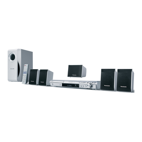
DVD Home Theater Sound System
SA-HT340EE
Colour
(S).......................Silver Type
Preset Memory:
lFrequency Modulation (FM)
Frequency Range:
Sensitivity:
S/N 26dB
Antenna Terminals:
lAmplitude Modulation (AM/ MW)
Frequency Range:
AM Sensitivity S/N 20dB at
999kHz:
lMic jack:
Sensitivity:
Terminal:
lDisc section
Discs played (8 cm or 12 cm):
(1) DVD [DVD-Video, DivX(*6,7)]
(2) DVD-RAM [DVD-VR, MP3(*2,7), JPEG(*4,7), MPEG4(*5,7),
DivX(*6,7)]
(3) DVD-R [DVD-Video, DVD-VR, MP3(*2,7), JPEG(*4,7),
MPEG4(*5,7), DivX(*6,7)]
(4) DVD-R DL [DVD-Video, DVD-VR]
(5) DVD-RW [DVD-Video, DVD-VR, MP3(*2,7), JPEG(*4,7),
MPEG4(*5,7), DivX(*6,7)]
© 2006 Panasonic AVC Networks Singapore Pte.
Ltd. All rights reserved. Unauthorized copying and
distribution is a violation of law.
ORDER NO.MD0605177CE
FM 15 stations
AM/MW 15 stations
87.5-108.00MHz
(50kHz step)
1.8µV (IHF)
1.4µV
75Ω (unbalanced)
522-1629kHz (9kHz step)
560µV/m
0.7mV (1.2kΩ)
Mono 6.3mm jack (1 system)
Advertisement
Table of Contents

Related Manuals for Panasonic SA-HT340EE


Summary of Contents for Panasonic SA-HT340EE
-
Page 1: Specifications
At 100Hz and total harmonic of 1% (5) DVD-RW [DVD-Video, DVD-VR, MP3(*2,7), JPEG(*4,7), lSubwoofer: 25 W/ Channel (5Ω) MPEG4(*5,7), DivX(*6,7)] © 2006 Panasonic AVC Networks Singapore Pte. Ltd. All rights reserved. Unauthorized copying and distribution is a violation of law. - Page 2 0.7 Vp-p (75 Ω) R output level: long and narrow pictures may not be displayed. 0.7 Vp-p (75 Ω) G output level: *5 MPEG4 data recorded with Panasonic SD multi cameras or 0.7 Vp-p (75 Ω) B output level: DVD video recorders. Terminal:...
- Page 3 SA-HT340EE...
-
Page 4: Table Of Contents
SA-HT340EE CONTENTS Page Page 1 Safety Precautions 11.1. Disassembly Procedure 1.1. GENERAL GUIDELINES 12 Measurements and Adjustments 1.2. Before Repair and Adjustment (Using SMPS) 12.1. Service Tools and Equipment 1.3. Protection Circuitry 12.2. Important points in adjustment 2 Prevention of Electro Static Discharge (ESD) to 12.3. -
Page 5: Safety Precautions
SA-HT340EE 1 Safety Precautions 1.1. GENERAL GUIDELINES 1. When servicing, observe the original lead dress. If a short circuit is found, replace all parts which have been overheated or damaged by the short circuit. 2. After servicing, see to it that all the protective devices such as insulation barriers, insulation papers shields are properly installed. -
Page 6: Prevention Of Electro Static Discharge (Esd) To Electrostatically Sensitive (Es) Devices
SA-HT340EE 1. Turn off the power. 2. Determine the cause of the problem and correct it. 3. Turn on the power once again after one minute. Note: When the protection circuitry functions, the unit will not operate unless the power is first turned off and then on again. -
Page 7: Precaution Of Laser Diode
SA-HT340EE 3 Precaution of Laser Diode CAUTION : This product utilizers a class 1 laser. Invisible laser radiation is emitted from the optical pick up lens. When the unit is turned on: Wavelength : 662nm/785nm Maximum output radiation power from pick up : 100µW/VDE Laser radiation from pick up unit is safety level, but be sure the followings: 1. -
Page 8: About Lead Free Solder (Pbf)
SA-HT340EE 4 About Lead Free Solder (PbF) 4.1. Service caution based on legal restrictions 4.1.1. General description about Lead Free Solder (PbF) The lead free solder has been used in the mounting process of all electrical components on the printed circuit boards used for this equipment in considering the globally environmental conservation. -
Page 9: Handling Precautions For Traverse Unit
SA-HT340EE 5 Handling Precautions for Traverse Unit The laser diode in the optical pickup unit may break down due to static electricity of clothes or human body. Special care must be taken avoid caution to electrostatic breakdown when servicing and handling the laser diode. - Page 10 SA-HT340EE...
-
Page 11: Accessories
SA-HT340EE 6 Accessories Video cable Remote control AM loop antenna Speaker label FM indoor antenna AC cord... -
Page 12: Operation Procedures
SA-HT340EE 7 Operation Procedures 7.1. Remote Control Key Buttons Operations... -
Page 13: Main Unit Key Buttons Operations (Sa-Ht340)
SA-HT340EE 7.2. Main Unit Key Buttons Operations (SA-HT340) OPEN CLOSE TUNING VOLUME SELECTOR AC IN ME MOR Y playback Disc playback Disc playback * TV works only when the scart cable is connected. -
Page 14: Disc Information
SA-HT340EE 7.3. Disc information 7.3.1. Disc playability (Media) - Page 15 SA-HT340EE 7.3.2. File Extension Type Support (WMA/MP3/JPEG/MPEG4/DivX)
-
Page 16: About Divx Vod Content
SA-HT340EE 7.4. About DivX VOD Content... -
Page 17: Self-Diagnosis And Special Mode Setting
SA-HT340EE 8 Self-Diagnosis and special mode setting 8.1. Service Mode Summary Table The service modes can be activated by pressing various button combination on the player and remote control unit. Below is the summary of major checking: Player buttons Remote control unit buttons... - Page 18 SA-HT340EE 8.2.1. Service Mode Table 1 Item Key Operation FL Display Mode Name Description Front Key Jitter check Jitter check In STOP (no disc) mode, Jitter rate is measured and displayed. press STOP button on the Measurement is repeatedly done in player, and "5"...
- Page 19 SA-HT340EE 8.2.2. Service Mode Table 2 Item Key Operation FL Display Mode Name Description Front Key Micro-processor firmware version Micro-processor In STOP (no disc) firmware version display & EEPROM checksum display. mode, press STOP button display & on the player, and "7"...
- Page 20 SA-HT340EE 8.2.3. Service Mode Table 3 Item Key Operation FL Display Mode Name Description Front Key In STOP (no disc) Timer 1 check Timer 1 check mode, press STOP button Laser operation timer is measured on the player, and "...
- Page 21 SA-HT340EE...
-
Page 22: Dvd Self Diagnostic Function-Error Code
SA-HT340EE 8.3. DVD Self Diagnostic Function-Error Code 8.3.1. Error Code Table 1 Error Diagnosis Contents Description of error Automatic FL Display Remarks Code Focus servo error Focus coil NG (OPU unit abnormal) Press [ n STOP] on main unit for next error. - Page 23 SA-HT340EE 8.3.2. Error Code Table 2 Error Diagnosis Contents Description of error Automatic FL Display Remarks Code F506 Invalid media Disc is flipped over, TOC unreadable, Press [ n STOP] on main incompatible disc media unit for next error F600...
-
Page 24: Sales Demonstration Lock Function
SA-HT340EE 8.3.3. Error Code Table 3 Error Diagnosis Contents Description of error Automatic FL Display Remarks Code F890 Sending message when Sending message to AV task Press [ n STOP] on main message is being sent to unit for next error... -
Page 25: Service Precautions
SA-HT340EE Note: The following buttons are invalid and the player displays “___LOCKED_” while the lock function mode is entered. Player , SELECTOR, , VOLUME KNOB, DISC CHECK, DISC CHANGE, DISC1-DISC5 Remote SLEEP, REPEAT, 0~9, , RETURN, TOP MENU, controller unit POSITION MEMORY, TUNER/BAND, D.MIX, CH SELECT/ TEST, SET UP/ MUTING, DISPLAY, GROUP, TV, VCR/... -
Page 26: Assembling And Disassembling
SA-HT340EE 9 Assembling and Disassembling “ATTENTION SERVICER” Be careful when disassembling and servicing. Some chassis components may have sharp edges. Special Note: 1. This section describes the disassembly procedures for all the major printed circuit boards and main components. 2. Before the disassembly process was carried out, do take special note that all safety precautions are to be carried out. -
Page 27: Disassembly Flow Chart
SA-HT340EE 9.1. Disassembly Flow Chart 9.2. Main Components and P.C.B. Locations... -
Page 28: Disassembly Of Top Cabinet
SA-HT340EE 9.3. Disassembly of Top Cabinet Step 1 Remove 4 screws. Step 2 Remove 3 screws. (Rear view) Step 3 Lift up and remove the top cabinet. 9.4. Disassembly of the DVD Lid (When taking out disc manually) Step 1 Detach the gear for drawing out tray from the mechanism unit. -
Page 29: Disassembly Of Front Panel
SA-HT340EE 9.5. Disassembly of Front Panel · Follow (Step 1) to (Step 3) of Item 9.3. Step 1 Remove the DVD lid. Step 2 Detach FFC cables at connectors. (CN2005, CN2006 & CN2007) Step 5 Detach the front panel. Step 3 Remove 1 screw. -
Page 30: Disassembly Of Dvd Mechanism Unit
SA-HT340EE 9.7. Disassembly of DVD Mechanism Unit · Follow (Step 1) to (Step 3) of Item 9.3. · Follow (Step 1) of Item 9.5. Step 1 Remove 2 screws. · Disassembly of Volume P.C.B. Step 2 Detach FFC cables at connectors. (CS901, CN2001). -
Page 31: Disassembly Of Rear Panel
SA-HT340EE · Follow (Step 1) to (Step 3) of Item 9.3. · Follow (Step 1) to (Step 4) of Item 9.9. Step 1 Remove 1 screw. Step 2 Detach cables at the connectors. (CN2, CN3) Step 3 Remove SMPS Module P.C.B. - Page 32 SA-HT340EE Step 2 Remove 2 screws. Step 3 Remove the digital amp IC (IC5100). Note: For disassembly IC5200 & IC5300, repeat the (Step 1) to (Step 3). Refer to the diagrams of Main P.C.B. (Section 19.2) for location of the parts.
-
Page 33: Service Position
SA-HT340EE 10 Service Position 10.1. Servicing position of the DVD Module P.C.B. · Follow Item 9.7. · Follow (Step 1) of Item 9.8. · Follow (Step 1) of Item 9.9. Step 1 Connect FFC cables at connectors. (CN2, CN3, CN2001, CN2004, CN2005, CN2006 & CN2007) Step 2 Connect fan unit (CN5704). -
Page 34: Assembly And Disassembly Of Mechanism Unit
SA-HT340EE 11 Assembly and Step 4 Remove the traverse unit. disassembly of Mechanism Unit 11.1. Disassembly Procedure 11.1.2. Disassembly of Tray Unit Step 1 Slide the guide tray unit while pressing the stopper in the arrow direction, and remove the guide tray unit. - Page 35 SA-HT340EE Step 3 Hook the drive arm concave phase over the tray and Step 4 Spread the tabs at the both sides and pull the tray out. the tray slider. (The tray slides a little forword and stops.). Step 4 Press in the tray.
- Page 36 SA-HT340EE Step 7 Turn the change lever in the arrow direction till it stops. Step 8 Hook the change lever spring on the change lever project part temporarily. Step 2 Hook the lock lever spring on the lock lever projection part temporarly.
- Page 37 SA-HT340EE 11.1.4. Disassembly of Tray Loading P.C.B. Step 1 Remove 3 screws Step 2 Remove 4 pins. 11.1.5. Disassembly of Optical Pickup Unit Special Note: Anti-static measures are necessary due to handling of OPU unit . Step 3 Remove the middle chassis.
- Page 38 SA-HT340EE Step 7 Remove 1 screw. Step 8 Slide the shaft in the arrow direction. Step 4 Remove the optical pickup unit in the arrow direction till it stops. Step 9 Lift the optical pickup unit with the shaft. Step 5 Remove 2 screws.
- Page 39 SA-HT340EE (Assembling the optical pickup unit) Step 1 Pass the intermediate FPC through the frame hole. Step 2 Align the guide section of the optical pickup unit with the rail. Step 3 Install the shaft top to the holder. Step 11 Pull the shaft and the rubber out.
-
Page 40: Measurements And Adjustments
SA-HT340EE 12 Measurements and Adjustments 12.1. Service Tools and Equipment Application Name Number Tilt adjustment DVD test disc DVDT-S20 [SPG] TORX screw driver (T6) Available on sales route. (T6) or RFKZ0185 [SPG] Others Grease RFKXPG641 [SPG] Confirmation CD test disc... -
Page 41: Optical Adjustment
SA-HT340EE 12.4. Optical adjustment 12.4.1. Optical pickup tilt adjustment Measurement point Adjustment point Mode Disc Tangential adjustment screw T01 (inner periphery) play DVDT-S20 [SPG] Tilt adjustment screw T30 (center periphery) T43 (outer periphery) play Measuring equipment Adjustment value None (Main unit display for servicing is used.) Adjust to the minimum jitter value. -
Page 42: Abbreviations
SA-HT340EE INITIAL/LOGO ABBREVIATIONS 13 Abbreviations ERROR TORQUE CONTROL ERROR TORQUE CONTROL REFERENCE INITIAL/LOGO ABBREVIATIONS ENCSEL ENCODER SELECT A0~UP ADDRESS ETMCLK EXTERNAL M CLOCK (81MHz/40.5MHz) ACLK AUDIO CLOCK ETSCLK EXTERNAL S CLOCK (54MHz) AD0~UP ADDRESS BUS FBAL FOCUS BALANCE ADATA AUDIO PES PACKET DATA... - Page 43 SA-HT340EE INITIAL/LOGO ABBREVIATIONS INITIAL/LOGO ABBREVIATIONS READ ENABLE VBLANK V BLANKING RFENV RF ENVELOPE COLLECTOR POWER SUPPLY RF PHASE DIFFERENCE OUTPUT VOLTAGE (CD-ROM) REGISTER SELECT VCDCONT VIDEO CD CONTROL (TRACKING RSEL RF POLARITY SELECT BALANCE) RESET DRAIN POWER SUPPLY VOLTAGE RESERVE...
-
Page 44: Voltage And Waveform Chart
SA-HT340EE 14 Voltage and Waveform Chart 14.1. DVD Module P.C.B. IC8001 Re f No. MODE CD P LAY Re f No. IC8001 MODE CD P LAY IC8001 Re f No. MODE CD P LAY IC8001 Re f No. MODE CD P LAY IC8001 Re f No. -
Page 45: Main P.c.b
SA-HT340EE 14.2. Main P.C.B. IC1101 Re f No. MODE CD P LAY S TANDBY IC1101 Re f No. MODE CD P LAY S TANDBY IC1102 Re f No. MODE CD P LAY S TANDBY IC2004 Re f No. MODE CD P LAY... -
Page 46: Fl P.c.b., Mic P.c.b. & Tray Loading P.c.b
SA-HT340EE Re f No. IC5100 MODE CD P LAY 25.9 12.7 12.6 12.7 12.7 S TANDBY 26.0 12.8 12.7 12.8 12.8 Re f No. IC5200 MODE CD P LAY 25.9 12.7 12.7 12.7 12.7 S TANDBY 26.0 12.7 12.7 12.8 12.7... -
Page 47: Waveform Chart
SA-HT340EE 14.5. Waveform Chart WF No. IC1101-4 (PLAY) WF No. IC1101-8 (PLAY) WF No. IC1101-11 (PLAY) WF No. IC1101-13 (PLAY) 0.7Vp-p(2msec/div) 1.1Vp-p(20usec/div) 1Vp-p(20usec/div) 0.5Vp-p(20usec/div) WF No. IC1101-15 (PLAY) WF No. IC1101-18 (PLAY) WF No. IC1101-21 (PLAY) WF No. IC1101-24, 27 (PLAY) 0.4Vp-p(20usec/div) -
Page 48: Illustration Of Ic's, Transistors And Diodes
SA-HT340EE 15 Illustration of IC's, Transistors and Diodes C0ABBB000230 (8p) C3ABPG000145 (54p) C0HBB0000057 (44p) C0GAY0000013 C1AB00002463 (100p) C0CBCBD00018 (8p) C3EBEG000072 (8p) C2CBYY000194 (100p) C0EBA0000029 (4p) C3EBGC000055 (8p) MN864701 (164p) C9ZB00000461 (32p) C0FBBK000050 (28p) MN2DS0009VP (256p) No.1 C1AB00001731 (6p) No.1 RFKWMHA0B160... -
Page 49: Wiring Connection Diagram
SPEAKER MOTOR ASS'Y CENTER SPEAKER CN5704 CN2006 SUBWOOFER FP8531 FP8251 FP8101 H2002 CN2005 H2001 DVD MODULE P.C.B. DVD MODULE P.C.B. (SIDE:B) (SIDE:A) TO FAN UNIT LOADING MOTOR CS901 TRAY LOADING P.C.B. (SOLDER SIDE) SMPS MODULE P.C.B. 230V...50HZ SA-HT340EE WIRING CONNECTION... - Page 50 SA-HT340EE...
-
Page 51: Block Diagram
ACT T+ LEVEL VOL1- ACT T- SHIFT RFINN FOCUS RFINP COIL ACT F+ ACT F- SPMUTE MUTE3 DRV4 MUTE VOL2+ TRVFT MUTE MUTE12 CH1,2 LEVEL VOL2- DRV3 MUTE SHIFT MUTE4 MUTE QR8571 BUFFER TRAVERSE INNER SW DRV2 SA-HT340EE BLOCK DIAGRAM... - Page 52 AND GATE DVD CLK OP CPU CLK NEXOE NEXWE NEXCE OP CPU CMD DVD CMD EXDT0 IC8695 C0JBAA000346 AND GATE DVD STAT OP CPU STAT DATA IC8601 C0EBA0000029 RESET IC8611 NRST EEPROM IC8606 EXDT15 C0EBE0000455 RESET (Not Supplied) SA-HT340EE BLOCK DIAGRAM...
- Page 53 Q2006 POWER ON ZFLAG RESET MUTING DVD MUTE DVD CLK DVD CLK DVD CMD IC2018 DVD CMD DVD STAT DVD STAT C2CBYY000194 ST/DO TUN DO SYSTEM CONTROL TUN DI TUN SD TUN CLK POWER SUPPLY (FM:ON) (FM) SA-HT340EE BLOCK DIAGRAM...
- Page 54 MOTOR DRIVE(LOADING) LOADING V REF MOTOR IC2004 DRIVE CONTROL EEPROM (Not Supplied) KEY SWITCH KEY SWITCH (S6801-6806) D6900 (S6800) Q2004 Z6900 VR6800 S902 (REMOTE SENSOR) (VOLUME) DRIVE Q2003 VREF+ X2001 S901 RESET VREF+ IC2018 C2CBYY000194 SYSTEM CONTROL SA-HT340EE BLOCK DIAGRAM...
- Page 55 CH1 INPUT H2001 CH1 - Q5740-5742 SUBWOOFER - +26V (VCC) OUTPUT Q5744-5746 MUTE +26V (VCC) MUTE FAN MOTOR FL00 DRIVE IC6901 X OUT C0HBB0000057 STANDBY Q2980 STANDBY CIRCUIT DISPLAY DRIVER X IN SWITCHING IC2018 C2CBYY000194 SYSTEM CONTROL AVSS SA-HT340EE BLOCK DIAGRAM...
- Page 56 SA-HT340EE...
-
Page 57: Schematic Notes
SA-HT340EE 18 Schematic Notes · This schematic diagram may be modified at any time with the development of new technology. Notes: S901: Play detection switch. S902: Open detection switch. S6800: Standby / on switch (POWER S6801: Tray open / close switch ( Open / Close). - Page 58 SA-HT340EE...
-
Page 59: Schematic Diagram
C8531 100P LDGND LB8561 J0JBC0000042 LDDVD LB8551 J0JBC0000042 GND(OEIC) C8533 VREF1 LB8531 ERJ2GE0R00X VREFH SUB2 RX8533 VIN6 (56 x 2) SUB1 VIN5 LPC2 PIN(CD) R8532 2.2K RAM_CD SUBSEL R8533 GND(VRCD) C8532 220P SA-HT340EE DVD MODULE (DV3.2)/ OPTICAL PICKUP UNIT CIRCUIT... - Page 60 AND GATE LOGIC IC C8691 LB8691 ERJ2GEJ101X R8557 C8553 C8551 6.3V47 R8556 C8552 C8554 R8558 R8553 OP_CPU_STAT 16V10 R8555 R8554 R8559 Q8552 C8695 B1ADGB000008 Q8551 R8551 LB8692 SWITCH ERJ2GEJ101X 2SD1819A0L LPC01 SWITCH LB8693 R8552 ERJ2GEJ101X OP_CPU_CMD SA-HT340EE DVD MODULE (DV3.2) CIRCUIT...
- Page 61 C8055 EXADR12 EXADR11 EXADR10 EXADR9 EXADR8 IC8051 C8022 C3ABPG000145 C8606 EXADR19 64MB SDRAM NEXWE EXADR18 R8601 EXADR17 100K EXADR7 C8601 EXADR6 EXADR5 EXADR4 EXADR3 EXADR2 EXADR1 IC8606 C0EBE0000455 IC8601 RESET C8008 C0EBA0000029 RESET C8602 0.015 SA-HT340EE DVD MODULE (DV3.2) CIRCUIT...
- Page 62 VIN5 EXADT3 VIN5 VIN5 EXADT2 VIN9 C8211 1200P VIN6 EXADT1 VIN10 D8211 MA2J11100L L8201 G1C100K00019 D+3.3V 65 66 67 68 69 70 71 72 73 L8501 G1C100K00019 C8528 C8529 R8003 C8201 C8501 6.3V100 6.3V100 C8505 SA-HT340EE DVD MODULE (DV3.2) CIRCUIT...
-
Page 63: B) Main/Power, Fl, Volume & Mic Circuit
MUTING L2804 J0JBC0000015 R2813 75 C2851 WIDE_OUT L2805 220P J0JBC0000015 R2816 75 Q2805 WIDE B1GBCFJJ0051 INVERTER L2806 C2853 COUT J0JBC0000015 R2817 75 100P W2509 W2512 L2807 C2803 J0JBC0000015 R2818 75 6.3V1000 W2595 YOUT C2831 C2830 1000P 1000P SA-HT340EE MAIN CIRCUIT... - Page 64 AVCC BRAKE_H R2092 RF_DET BRAKE_H W2583 W2588 5 6 7 8 9 RESET D2005 B0ACCK000005 R2096 R2032 R2019 C2007 C2006 R2001 100K 50V3.3 Q2003 R2095 4.7K B1GBCFJJ0051 RESET D2008 CNVSS R2017 B0ACCK000005 W2586 W2537 X2001 H2B100500004 10MHz SA-HT340EE MAIN CIRCUIT...
- Page 65 MIXL C2301 INL1 SLSELOUT ASP_MICIN MICIN SLVOLIN C6920 R6920 AGND SLNFIN C2295 1 LINEOUT-R R2301 RECOUTR SLVOLOUT 1.8K LINEOUT-L RECOUTL SLFIN C2195 1 C2303 C2302 0.047 0.033 5 6 7 8 9 C2502 0.047 C2503 0.047 R2303 SA-HT340EE MAIN CIRCUIT...
- Page 66 R5764 R5758 Q5741 FAN MOTOR DRIVE 3.9K 3.3M FANLOCK B1ABCF000176 FAN MOTOR DRIVE R5763 2.7K Q5742 B1ABCF000176 Q5746 FAN MOTOR DRIVE R5762 B1GBCFJJ0051 150K R5756 FAN MOTOR DRIVE D5743 W2571 B0ACCK000005 FANDCOUT(+) W2527 0 PCONT C5797 50V1 SA-HT340EE MAIN CIRCUIT...
- Page 67 B1BACG000023 D2939 R1200 R1203 R2971 R2926 DVD 2.7V REGULATOR B0EAKM000117 LINEOUT-R RCH_OUT DVD_+2.7V R1201 R2972 R2973 W2574 L2902 Q1200 G0A101G00022 SCART_MUTE B1ABCF000176 W2550 Q1001 L2909 B1GDCFJJ0047 R1101 G0A200D00002 Q1100 B1ABCF000176 W2542 W2543 W2560 R1100 R1103 LINEOUT-L LCH_OUT SA-HT340EE MAIN CIRCUIT...
- Page 68 W2515 C0ABBB000230 W2519 220P OP-AMP W2513 W2528 W2597 C6709 R6709 C6710 C6707 C6708 CN2006 H6903 ASP_MICIN ASP_MICIN ASP_MICIN L6083 JK6802 J0JBC0000019 W2547 R6708 R6707 C6711 MIC_AGND MIC_AGND C2900 16V470 MIC_SW MIC_SW MIC_SW C6093 0.047 W6516 L6081 ERJ3GEY0R00V SA-HT340EE MAIN/FL/VOLUME CIRCUIT...
-
Page 69: C) Tray Loading & Tuner Extent Circuit
TUNER RCH TUNER RCH TO TUNER TUNER DO/ST TUNER DO/ST MAIN CIRCUIT PACK TUNER LCH TUNER LCH (CN2002) on (J3CCBC000012) TUNER SD TUNER SD SCHEMATIC TUNER DI TUNER DI DIAGRAM-5 TUNER CLK TUNER CLK PORT_SEL PORT_SEL SA-HT340EE TUNER EXTENT/TRAY LOADING CIRCUIT... - Page 70 SA-HT340EE...
-
Page 71: Printed Circuit Board
C8013 C8016 C8015 R8011 RX8017 LB8693 RX8012 LB8692 RX8018 RX8016 RX8015 RX8014 RX8011 RX8019 C8057 C8421 C8427 C8422 IC8421 QR8420 C8424 C8428 C8426 FP8251 (TO SPINDLE/ TRAVERSE MOTOR) 3118A 3118A 3118A 3118A (SIDE A) (SIDE B) SA-HT340EE DVD MODULE P.C.B. -
Page 72: B) Main/Power
R5104 R5108 W2521 R2981 W2226 R5111 Q5742 H2002 R5102 (TO SMPS MODULE) Q2980 HEATSINK W2531 R2900 D2900 W2539 W2139 CN2005 C2904 H2001 (TO SMPS MODULE) E2900 Q5744 R5759 W2322 R5760 W2502 D5302 W2262 W2232 W2153 0490A-3 0490A-3 SA-HT340EE MAIN P.C.B. -
Page 73: C) Fl, Volume, Mic, Tray Loading & Tuner Extent P.c.b
C6093 0490A-3 0490A-3 C6703 H6903 R6705 VOLUME R6709 TUNER EXTENT P.C.B. TRAY LOADING P.C.B. (REP3288B) (REPX0531C) 0490A-3 0490A-3 LOADING IC904 CN2010 (TO TUNER PACK) MOTOR S902 CS901 (OPEN SW) S901 CP2010 (PLAY SW) 2462A 2462A SA-HT340EE FL/VOLUME/MIC/TRAY LOADING/TUNER EXTENT P.C.B. - Page 74 SA-HT340EE...
-
Page 75: Basic Troubleshooting Guide
SA-HT340EE 21 Basic Troubleshooting Guide 21.1. Basic Troubleshooting Guide for Traverse Unit (DVD Module P.C.B.) Problems Checking Points Checking components 1) Distorted picture or abnormal a) Check SDRAM address, data bus, CLK and IC8051 sound is heard during initialisation other control signals waveform... -
Page 76: Overall Block (Ht340)
SA-HT340EE 22 Overall Block (HT340) -
Page 77: Ht340 Dvd Unit Block
SA-HT340EE 22.1. HT340 DVD Unit Block... -
Page 78: Ht340 Block (Analog Signal : Dvd 5.1Ch Play Back Mode)
SA-HT340EE 22.2. HT340 Block (Analog Signal : DVD 5.1ch Play Back Mode) -
Page 79: Ht340 Block (Analog Signal : 2Ch Analog Input Mode)
SA-HT340EE 22.3. HT340 Block (Analog Signal : 2ch Analog Input Mode) -
Page 80: Ht340 Power Supply Block
SA-HT340EE 22.4. HT340 Power Supply Block... -
Page 81: Ht340 Power (Main) Block
SA-HT340EE 22.5. HT340 Power (Main) Block... -
Page 82: Terminal Function Of Ics
SA-HT340EE 23 Terminal Function of ICs 23.1. IC2018 (C2CBYY000194): Terminal Name Function Microprocessor IC 49 N.C No connection 50 N.C No connection Terminal Name Function 51 N.C No connection 52 N.C No connection 1 TRAY_ Loading mechanism close SW ( L: SW 53 N.C... -
Page 83: Exploded Views
SA-HT340EE 24 Exploded Views 24.1. Cabinet Parts Location... - Page 84 SA-HT340EE...
-
Page 85: Packaging
SA-HT340EE 24.2. Packaging... -
Page 86: Replacement Parts List
SA-HT340EE 25 Replacement Parts List Notes: *Important safety notice: Components identified by mark have special characteristics important for safety purpose. Furthermore, special parts which have purposes of fire-retardant (resistors), high-quality sound (capacitors), low-noise (resistors), etc. are used. When replacing any of components, be sure to use only manufacture’s specified parts shown in the parts list. -
Page 87: Component Parts List
SA-HT340EE 25.1. Component Parts List Ref. Part No. Part Name & Description Remarks RXQ0946 TRAVERSE MOTOR ASS’Y Ref. Part No. Part Name & Description Remarks RXQ1389 DVD OPU SUB ASS’Y CABINET AND CHASSIS PRINTED CIRCUIT BOARDS J3CCBC000012 TUNER PACK REP4012B DVD MODULE P.C.B. - Page 88 SA-HT340EE Ref. Part No. Part Name & Description Remarks Ref. Part No. Part Name & Description Remarks Q2914 B1BACG000023 TRANSISTOR S6804 EVQ21405R SW STOP Q2915 B1GBCFJJ0051 TRANSISTOR S6805 EVQ21405R SW PLAY Q2916 B1GBCFJJ0051 TRANSISTOR S6806 EVQ21405R SW SELECTOR Q2917 B1GBCFJJ0051...
- Page 89 SA-HT340EE Ref. Part No. Part Name & Description Remarks Ref. Part No. Part Name & Description Remarks LB8303 J0JBC0000042 CHIP INDUCTOR N2QAYZ000005 REMOTE CONTROL LB8304 J0JBC0000042 CHIP INDUCTOR A1-1 RKK-HTR0051K R/C BATTERY COVER LB8305 J0JBC0000042 CHIP INDUCTOR K2CQ2CA00002 AC CORD...
- Page 90 SA-HT340EE Ref. Part No. Part Name & Description Remarks Ref. Part No. Part Name & Description Remarks R2060 ERJ3GEYJ221V 220 1/16W R2402 ERJ3GEYJ103V 10K 1/16W R2061 ERJ3GEYJ473V 47K 1/16W R2403 ERJ3GEYJ103V 10K 1/16W R2062 ERJ3GEYJ221V 220 1/16W R2404 ERJ3GEYJ123V 12K 1/16W...
- Page 91 SA-HT340EE Ref. Part No. Part Name & Description Remarks Ref. Part No. Part Name & Description Remarks R2971 ERX2SJ1R5E 1.5 2W R6703 ERJ3GEYJ681V 680 1/16W R2972 ERJ3GEYJ220V 22 1/16W R6705 ERJ3GEYJ102V 1K 1/16W R2973 ERJ3GEYJ151V 150 1/16W R6706 ERJ3GEY0R00V 0 1/16W...
- Page 92 SA-HT340EE Ref. Part No. Part Name & Description Remarks Ref. Part No. Part Name & Description Remarks R8565 ERJ2GEJ2R2X 2.2 2W W2547 ERJ6GEY0R00V CHIP RESISTOR R8566 ERJ3GEYJ560V 56 1/16W W2548 ERJ6GEY0R00V CHIP RESISTOR R8567 ERJ3GEYJ510V 51 1/16W W2550 ERJ6GEY0R00V CHIP RESISTOR...
- Page 93 SA-HT340EE Ref. Part No. Part Name & Description Remarks Ref. Part No. Part Name & Description Remarks C1005 ECJ1VB1H103K 0.01 50V C2283 ECJ1VB1A105K 1 10V C1006 ECJ1VB1H104K 0.1 50V C2295 ECJ1VB1A105K 1 10V C1007 ECA1HM220B 22 50V C2300 ECJ1VB1A105K 1 10V...
- Page 94 SA-HT340EE Ref. Part No. Part Name & Description Remarks Ref. Part No. Part Name & Description Remarks C2827 ECJ1VC1H101J 100P 50V C5105 ECJ1VB1H221K 220P 50V C2828 ECJ1VC1H101J 100P 50V C5106 ECJ1VB1C224K 0.22 16V C2829 ECJ1VC1H101J 100P 50V C5107 ECJ1VB1C224K 0.22 16V...
- Page 95 SA-HT340EE Ref. Part No. Part Name & Description Remarks Ref. Part No. Part Name & Description Remarks C6905 ECA1HM220B 22 50V C8313 ECJ1VB0J105K 1 6.3V C6906 ECJ1VC1H101K 100P 50V C8325 ECJ0EF1C104Z 0.1 16V C6909 ECJ1VB1H103K 0.01 50V C8331 ECJ0EF1C104Z 0.1 16V...