Table of Contents
Advertisement
Quick Links
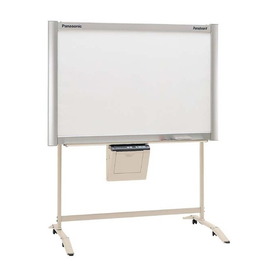
[Stand (option)]
[Wall-mounting (option)]
The unit in the picture is UB-5320.
Stand and Wall-mounting kit are optional.
• To assemble this unit, please refer to the Installation Manual.
• Before operating this unit, please read these instructions completely and keep them carefully for future reference.
Electronic Board
Operating Instructions
With Installation Manual
(for qualified service personnel)
English . . . . . . . . . . . . . . . . . 1–45
中 文 . . . . . . . . . . . . . . . . . 47–91
UB-5320
Model No.
UB-5820
Advertisement
Chapters
Table of Contents

Related Manuals for Panasonic UB-5320


Summary of Contents for Panasonic UB-5320
- Page 1 Operating Instructions With Installation Manual [Stand (option)] [Wall-mounting (option)] (for qualified service personnel) The unit in the picture is UB-5320. Stand and Wall-mounting kit are optional. UB-5320 Model No. UB-5820 English ....1–45 中...
- Page 2 Thank you for purchasing the Panasonic Electronic Board. For optimum performance and safety, please read these instructions carefully. Record these items for future reference Model number: _________________________ Date of purchase: ________________________ Serial number: _________________________ Dealer’s name: __________________________ Dealer’s address: ______________________________________________________________________...
-
Page 3: Table Of Contents
• Removing Panasonic-DMS ........ -
Page 4: For Your Safety
OF MOISTURE. cover is obtained. A replacement fuse cover can be THE SOCKET-OUTLET MUST BE NEAR THIS purchased from your local Panasonic Dealer. EQUIPMENT AND MUST BE EASILY ACCESSIBLE. If the fitted moulded plug is unsuitable for the socket The product should be used only with the power cord outlet in your home then the fuse should be removed that is supplied by the manufacturer. -
Page 5: Precautions
Precautions Precautions Never remove the cover, take apart or modify the Do not position the electronic board in a location where product. This will void the warranty. it is unstable. Do not put drinks, other liquids or heavy items on the After installing or moving the electronic board, lock the tray or screen. -
Page 6: Cd-Rom
Precautions Do not lean against the screen or on the cover (lower), Have the unit installed, removed and even if the electronic board is mounted on the wall. disposed of only by qualified service personnel. CHOKING HAZARD When the unit will no longer be used, in order to prevent it from falling, do not leave the unit Keep the marker’s cap out of reach of installed, but remove it. - Page 7 • Use a shielded USB cable that is certified as logo by USB-IF. • If you connect the electronic board to a USB hub, it is not guaranteed to work. • Do not connect two or more Panasonic electronic boards to a computer. It may cause the computer operation to become unstable.
-
Page 8: Part Names And Functions
Part Names and Functions Part Names and Functions Scanner Screen Printer Tray Stand The stand is optional. Output Port Control Panel (See page 9 for details.) Power Switch USB Connector (ON) (See page 13.) (OFF) AC Inlet Printer Door Open this door to load Power Cord copy paper or to remove jammed paper. -
Page 9: Control Panel
Part Names and Functions ■ Control panel Advance Key Contrast Indicator Copy Key Contrast Key Multi-Copy/Stop Key 2-Screen Copy Key Multi-Copy/Error Indicator Panel Name Description This lamp indicator displays the printing contrast used during copying. Contrast Indicator off: Normal printing contrast Indicator Indicator on: Darker than normal printing contrast Each time this key is pressed, the unit will alternate between... -
Page 10: Loading Copy Paper
Loading Copy Paper Note Loading Copy Paper • Use copy paper roll with a core diameter of 25.4 mm (1 inch) or more. Using a copy Set the power switch to on ( I ). paper roll with a smaller core could cause •... -
Page 11: Making Copies
Making Copies Note Making Copies • While copying, do not touch the paper, otherwise the paper may jam. This section describes how to copy text and • Text or images in shades of yellow will not illustrations drawn on the screen. copy. -
Page 12: Paper Jams
Paper Jams Pass the paper over the paper feed roller and Paper Jams under the cutter cover, then through the output port about 4 cm. (Refer to step 4 on page 10.) In case paper cannot go through, just put the To release jammed paper: paper on the paper feed roller and insert the top of the paper in the cutter cover as shown... -
Page 13: Computer Interfacing
• If you connect the electronic board to a USB hub, it is not guaranteed to work. • Do not connect two or more Panasonic electronic This electronic board does not function with Hi-Speed boards to a computer. It may cause the computer USB 2.0. -
Page 14: Installing Drivers / Board Image Capture
Computer Interfacing ■ Installing Drivers / Board Image Read “End-User License Agreement” carefully Capture and click [Yes]. When the following window appears, check The USB, printer, TWAIN driver and Board Image that the electronic board is not connected to Capture are installed in your computer by following your computer and click [OK]. -
Page 15: Installing Quick Image Navigator / Panasonic-Dms
Windows 7: Quick Image Navigator For Windows 98 / Windows Me: Panasonic-DMS ■ Removing Drivers / Board Image If Panasonic-DMS is already installed, you do not Capture / Quick Image Navigator need to uninstall it. If you need to remove the USB driver, printer driver, Power on your computer and start Windows. -
Page 16: Removing Panasonic-Dms
(2-Screen Scan) button. ■ Removing Panasonic-DMS • When scanning is completed, the Save Scan Image dialog box appears. If you need to remove Panasonic-DMS, perform the following steps. Power on your computer and start Windows. Click [Start], move the pointer to Programs–... -
Page 17: Scanning With The Quick Image Navigator / Panasonic-Dms
Computer Interfacing For Panasonic-DMS: Click the File menu, then Note click Select source..• Board Image Capture cannot be started while the Select Panaboard UB5-7 USB TWAIN Driver Panaboard Operation Panel is displayed using Quick and click [Select]. Image Navigator or Panasonic-DMS. To start Board... -
Page 18: Panaboard Operation Panel
Computer Interfacing ■ Panaboard Operation Panel It is possible to perform the same operations as with the electronic board control panel (page 9) from the following Panaboard Operation buttons. Note • While the Panaboard Operation Panel is displayed, the Copy Key and 2-Screen Copy Key on the electronic board control panel are used for scanning images into the computer. -
Page 19: Printing
Computer Interfacing Panel Name Description The status box displays the status of the TWAIN driver and the electronic board. Stand by: The electronic board is stand by. Both of the Panaboard Operation Panel and the electronic board control panel are operational. Rotating: The electronic board is rotating the screen. -
Page 20: Daily Care And Maintenance
Daily Care and Maintenance ■ Caring for the eraser Daily Care and Maintenance When the erasing surface of the eraser becomes dirty, hold down the sheet under the top sheet with your finger and peel off the dirty sheet (white or gray Always turn off the power switch and unplug the sheet) by pulling in the direction of the arrow. -
Page 21: Cleaning The Printer Head And Paper Feed Roller
Daily Care and Maintenance ■ Cleaning the printer head and Clean the Paper Feed Roller paper feed roller Wipe any dirt or stains off the paper feed roller. If black streaks appear on the copy, clean the printer head and the paper feed roller. Push the door open button and open the printer door. -
Page 22: Help Troubleshooting
Install the new Panasonic-DMS again as follows. menu or cannot be used after 1. Uninstall the current Panasonic-DMS. 15-16 installing the Panasonic- 2. Install the old Panasonic-DMS. DMS. 3. Install the new Panasonic-DMS in the same folder with the old one. -
Page 23: Meanings Of Error Codes
Troubleshooting Symptom Care and Remedy Page The old Panasonic-DMS is not uninstalled if the old version of the Panasonic Document Panasonic-DMS has been installed before installing the new one. Management System menu Uninstall the old Panasonic-DMS from the Add / Remove is remained in the Programs Programs of the Control Panel. -
Page 24: Specifications
Specifications Specifications Model No. UB-5320 UB-5820 General Power supply Refer to the name plate on the printer Power consumption (Operational) Refer to the name plate on the printer 1504 mm × 1550 mm 1504 mm × 1912 mm External dimensions (Height ×... - Page 25 Installation Manual (for qualified service personnel) Table of Contents page Assembling the Electronic Board ..... . . 26 ●Accessories for assembling ....... 26 ●Assembly .
-
Page 26: Assembling The Electronic Board
The package includes the parts for setting up the electronic board shown below. Make sure that all of these parts are included in the package before proceeding. Illustration / Quantity Part Name Remarks UB-5320 / UB-5820 Q’ty Screen fastening bracket Upper frame cover... -
Page 27: Assembly
■ If you are using a wall-mounting kit, refer to page 42. Remove the electronic board from the shipping box. Remove the joints, then remove the electronic board from the shipping box. [UB-5320] Lower frame cover Upper frame cover Screen fastening brackets... - Page 28 Assembling the Electronic Board [UB-5820] Screen fastening brackets Wrench Eraser Wing bolts Hexagonal screws Markers Manuals, CD-ROM Lower frame cover Upper frame cover Copy paper roll Shipping box Power cord Scanner /printer unit Paper holders Screen unit Joints Joints Shipping box Caution •...
- Page 29 Assembling the Electronic Board Collapse the shipping box. Attach the scanner / printer unit to the optional stand or wall-mounting Remove the tape on the unopened side of the kit. shipping box, then collapse the box. ■ If you are using the stand (option): 1) Hang the scanner / printer unit on the stand fixtures using the wing bolts A or B.
- Page 30 Assembling the Electronic Board ■ If you are using the wall-mounting Insert the two supplied screen kit (option): fastening brackets into the screen unit frame. 1) Hang the scanner / printer unit on the wall- mounting fixtures using the wing bolts A or B (➊).
- Page 31 Assembling the Electronic Board Fasten the brackets. Attach the screen unit to the scanner / printer unit. 1) Move the screen fastening brackets toward the center and fasten them with the four 1) Set the two provided hexagonal screws to the hexagonal screws provided.
- Page 32 Assembling the Electronic Board 3) Fasten the two screws (➊), then secure the 5) Fasten the hexagonal screw (➋) while screen unit with the two provided hexagonal pressing the gear fixing bracket in the screws (➋). direction of the arrow (➊). Hexagonal screw Gear fixing bracket Remove the tape fastening the...
- Page 33 Assembling the Electronic Board Remove the roller and paper. 2) Be sure the back of the frame cover (A) is fit to the frame of the screen unit and push down the two rivets. Bend and remove the roller (➊), then remove the paper with tape (➋).
- Page 34 Assembling the Electronic Board Attach the lower frame cover. Attach the paper holders. Install the paper holders to the holes in 1) Align the lower frame cover with the metal numerical order of the arrows (1), (2), (3) and fittings on the left and right ends (➊), then (4).
- Page 35 Assembling the Electronic Board Wipe the screen film surface. Soak a soft cloth with water, wring well, and wipe the screen film surface. Caution • Do not wipe the screen film surface with paint thinner, benzene, or cleaners that contain abrasives.
-
Page 36: Electronic Board Operations Check
Electronic Board Operations Check After assembling the electronic board, perform the procedures presented in the following table to make sure it functions properly. Points to Check Step Symptom Solutions Turn on the power switch. “ ” flashes after “ ” lights (Normal operation) (If not) Check power cord. -
Page 37: Repacking
Repacking Perform Assembly Steps 2 through 16 on pages 27 - 34 in reverse to repack the electronic board and accessories. Use the joints to fasten the shipping box. Caution • When handling the screen unit, grasp the metal frames on both sides of the screen. Do not grasp the screen film surface, as this may scratch it. -
Page 38: Assembling The Optional Stand (Kx-B061)
Assembling the Optional Stand (KX-B061) ■ Accessories The package box for the optional stand includes the parts noted below; please confirm that all parts are present before beginning installation Part name Illustration Q’ty Part name Illustration Q’ty Stand base Wing bolt M5 x 12 mm ( ”) Support... -
Page 39: Assembly
Assembling the Optional Stand (KX-B061) ■ Assembly Assembling the stand ■ Assembling the fall-prevention extension legs The fall-prevention extension legs increase the safety of the electronic board. • Caster locks are attached to Fall-prevention extension legs the back side. Caution •... - Page 40 Assembling the Optional Stand (KX-B061) ■ Assembling the stand Assemble with the holes toward the front. Pull the fall-prevention extension legs Locking down (fall-prevention extension legs casters side will be fixed by the lock pin.) (rear) Locking casters side (rear) Note Do not tighten the screw too much.
- Page 41 Assembling the Optional Stand (KX-B061) Attach the fixtures with the four wing-bolts. Assemble and install the electronic board. Refer to page 27.
-
Page 42: Optional Wall-Mounting Kit (Kx-B063)
UB-5320 is 175 kgf (386 lbs.). UB-5820 is 185 kgf (408 lbs.). 2. The position of the intended installation is of adequate size for the selected Panaboard. UB-5320 is 1,664 mm (H) × 1,550 mm (W) [5' 6 (H) × 5' 2 "... -
Page 43: Wall-Mounting Procedure
Confirm that the wall is strong enough to support the weight of the electronic board. Caution The wall must be capable of supporting at least 1,716 N [175 kgf (386 lbs.)] for UB-5320 1,814 N [185 kgf (408 lbs.)] for UB-5820. Tape the Wall-mounting template on the wall. -
Page 44: Attaching The Wall-Mounting Fixtures
Optional Wall-mounting Kit (KX-B063) ■ Attaching the wall-mounting fixtures The electronic board must be mounted with the method most suited to the material of the wall. Three methods are presented here. (Other options may be available in your area.) ● Attaching to metal or concrete walls Stud plugs (sold in stores) are needed. - Page 45 Optional Wall-mounting Kit (KX-B063) ● Attaching to plasterboard walls Split-wing toggles (sold in stores) are needed. Split-wing toggle Insert each bolt through a hole Wall-mounting in the wall-mounting fixture and Plasterboard fixture into the hole in the wall beneath so that the arms of the split- Bolt wing toggle are horizontal.