Table of Contents
Advertisement
Dolby noise reduction manufactured under license from Dolby
Laboratories Licensing Corporation.
"DOLBY" and the double-D symbol
Laboratories Licensing Corporation.
It is the intent of Sharp that this product be used in full compliance
with the copyright laws of the United States and that prior permission
be obtined from copyright owners whenever necessary.
US and foreign patents licensed from Dolby Laboratories Licensing
Corporation.
IMPOTANT SERVICE NOTES .......................................................................................................................................... 2
SPECIFICATIONS ............................................................................................................................................................. 2
NAMES OF PARTS ........................................................................................................................................................... 3
OPERATION MANUAL ...................................................................................................................................................... 6
QUICK GUIDE ................................................................................................................................................................... 8
DISASSEMBLY .................................................................................................................................................................. 9
REMOVING AND REINSTALLING THE MAIN PARTS ................................................................................................... 13
ADJUSTMENT ................................................................................................................................................................. 16
WIRING DIAGRAM .......................................................................................................................................................... 30
BLOCK DIAGRAM ........................................................................................................................................................... 32
SCHEMATIC DIAGRAM / WIRING SIDE OF P.W.BOARD ............................................................................................. 36
NOTES ON SCHEMATIC DIAGRAM .............................................................................................................................. 62
TYPE OF TRANSISTOR AND LED ................................................................................................................................. 62
WAVEFORMS OF CD CIRCUIT ...................................................................................................................................... 63
WAVEFORMS OF MD CIRCUIT ..................................................................................................................................... 64
TROUBLESHOOTING (CD SECTION) ........................................................................................................................... 66
TROUBLESHOOTING (MD SECTION) ........................................................................................................................... 70
FUNCTION TABLE OF IC ................................................................................................................................................ 75
REPLACEMENT PARTS LIST/EXPLODED VIEW/PACKING OF THE SET
SERVICE MANUAL
are trademarks of Dolby
CONTENTS
SHARP CORPORATION
- 1 -
MD-X60
• In the interests of user-safety the set should be restored to its original
condition and only parts identical to those specified should be used.
This document has been published to be used
for after sales service only.
The contents are subject to change without notice.
MD-X60
No.S6839MDX60///
Page
Advertisement
Table of Contents
Troubleshooting

Related Manuals for Sharp MD-X60


Summary of Contents for Sharp MD-X60
-
Page 1: Table Of Contents
Laboratories Licensing Corporation. • In the interests of user-safety the set should be restored to its original It is the intent of Sharp that this product be used in full compliance condition and only parts identical to those specified should be used. -
Page 2: Impotant Service Notes
MD-X60 FOR A COMPLETE DESCRIPTION OF THE OPERATION OF THIS UNIT, PLEASE REFER TO THE OPERATION MANUAL. IMPORTANT SERVICE NOTES BEFORE RETURNING THE AUDIO PRODUCT (Fire & Shock Hazard) Before returning the audio product to the user, perform the following safety checks. -
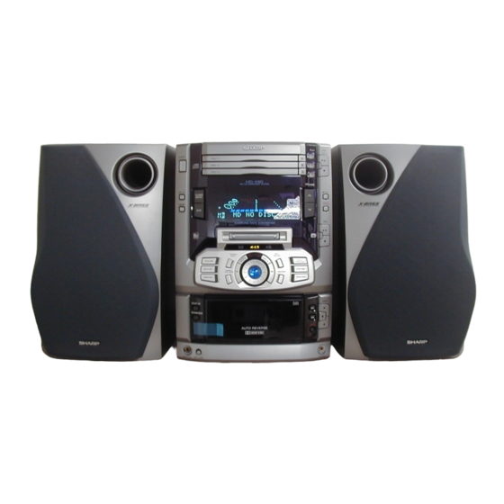
Page 3: Names Of Parts
MD-X60 NAMES OF PARTS Front panel Power Button: POWER Tuner Call (Band Select) Button: TUNER (BAND) Preset Equalizer Button: PRE-EQ Extra Bass Button: X-BASS Auxiliary Input (Digital/Analog) Select Button: AUX MD Compartment Sampling Frequency Indicators (CD) Open/Close Buttons: (CD) Play Buttons: 1... -
Page 4: 12. Level Meters
MD-X60 Display window (CD/MD) Music Schedule Indicators Level Meters (CD/MD) More Tracks Indicator: Character Information Display (TAPE) Direction Indicators: CD Indicator (TAPE) Loading Indicator (TAPE) Recording Indicator (TAPE) Reverse Mode Indicator (TAPE) Dolby NR Indicator: MD Indicator Pole Position Record Indicator... - Page 5 MD-X60 Remote control Remote Control Transmitter LED (MD/CD/TUNER) Direct Key (CD/MD) Program Button: PROGRAM (CD/MD) Program Clear Button: CLEAR (CD/MD) Play Mode Button: P-MODE Tuner control section Tuner Call (Band Select) Button: TUNER/BAND FM Stereo Mode Button: ST MODE MD control section...
-
Page 6: Operation Manual
MD-X60 OPERATION MANUALNAMES OF PARTS – 6 –... - Page 7 MD-X60 – 7 –...
-
Page 8: Quick Guide
MD-X60 QUICK GUIDE – 8 –... -
Page 9: Disassembly
MD-X60 DISASSEMBLY STEP REMOVAL PROCEDURE FIGURE Caution on Disassembly The disassembling the machine or assembling it after CD Mechanism 1. Screw ....(V1) x7 11-1 repair, observe the following instructions so as to ensure 2. Top Bord ... (V2) x1 3. - Page 10 MD-X60 (C2) x2 (J1) x1 ø3 x10mm Front Panel ø3 x10mm Front Panel (C1) x6 (J1) x1 (D3) x1 ø1.7 x3mm CD Chenger Pull Block (H1) x1 Pull ø3 x10mm (D3) x2 MD Holder Pull Pull (D2) x6 (D1) x1 ø3 x10mm...
- Page 11 MD-X60 (V3) x1 Push (V1) x2 (V5) x1 ø2 x7mm ø2.6 x12mm Pawl (V6) x1 (V7) x1 Spring Mechanism (V2) x1 (V8) x4 (V5) x2 ø2.6 x10mm ø2 x6mm (V1) x1 ø3 x10mm PWB-B8 (V1) x2 ø3 x8mm Turn clockwise the...
- Page 12 MD-X60 MD Mechanism (Y1)x4 ø1.7x8.9mm Figure 12-1 SPEAKER STEP REMOVAL PROCEDURE FIGURE Speaker 1. Net ..... (A1) x9 12-2 2. Front Panel ..(A2) x9 3. Screw ....(A3) x9 12-3 SPEAKER Super Tweeter Front Panel ( A2 ) x1...
-
Page 13: Removing And Reinstalling The Main Parts
MD-X60 REMOVING AND REINSTALLING THE MAIN PARTS MD MECHANISM SECTION (A1)x1 ø1.7x5mm Perform steps 1 to 9,21 and 23 of the disassembly method to remove the MD mechanism.(Refering to p.9~12) How to remove the magnetic head (See Fig. 13-1) Magnetic Head 1. - Page 14 MD-X60 How to remove the sled motor/loading motor (D1)x2 (D1)x2 (See Fig. 14-1) Ø1.7x2mm Ø1.7x2mm 1. Remove the screws (D1) x 4 pcs., and remove the sled motor/loading motor. Caution: Be careful so that the gear is not damaged. Gear (The damaged gear emits noise during searching.)
-
Page 15: Cd Mechanism Section
MD-X60 CD MECHANISM SECTION (A1) x2 ø2.6 x5mm For the procedure to remove the CD mechanism from the Stop Washer (A3) x1 main unit, refer to Disassembling Procedure, Steps 1~3, and 20. (p.9~11). Pickup How to Remove the optical pickup (See Fig. -
Page 16: Adjustment
MD-X60 ADJUSTMENT TUNER SECTION fL: Low-range frequency • TEST mode setting method fH: High-renge frequency Holding down the ENTER button and TUNER (BAND) button, • AM adjustment and confirmation turn on the power. Frequency is set in the memory (initial AM signal oscillator Frequency 400 Hz, 30%, AM modulation setting) as shown in Table 16. -
Page 17: Tape Section
MD-X60 TAPE SECTION Adjusting the mechanism Adjusting the deck circuit Driving Force Check Torque Meter Specified Value Position of each swich or control Play:TW-2412 120 g or more VOLUME Reverse Play:TW-2422 120 g or more FUNCTION TAPE TAPE NORMAL DOLBY NR... -
Page 18: Cd Test Mode
MD-X60 CD TEST MODE CD test mode setting Any one of test mode can be set by pressing several buttons as follows. Holding down VOL-UP and CD DISC 3 PLAY, turn on POWER. TEST: CD operation test Test Mode Function - CD TEST mode Setting of Test mode Initialization is not performed. - Page 19 MD-X60 MD SECTION When the combination of mechanism/pickup and PWB was changed , set the TEST mode to perform the AUTO preliminary adjustment and AUTO adjustment, write the adjustment data in EEPROM. When EEPROM was replaced, set the TEST mode,write the EEPROM set data (p28,p29) and then perform the preliminary adjustment and AUTO adjustment, write adjustment data in EEPROM.
- Page 20 MD-X60 2. Test mode Test mode setting method 1. Holding down the POLE POSITION button and MD (PLAY/PAUSE) button, press the POWER button. (State A is changed to state B .) 2. Insert the playback disc 1 (high reflection disc) or recording disc 2 (low reflection disc). (State C is set.) Thus, the test mode state is set.
- Page 21 MD-X60 1. EJECT mode Step No. Setting Method Remarks Display Step 1 Testmode EJECT state [ _ _ E J E C T _ _ _ ] Step 2 Press oncethe CD STOP button. Max. power output state [ x p w _ _ _ _ _ _ _ ] Step 3 Press once the CD STOP button.
- Page 22 MD-X60 4. EEPROM setting mode a) Focus setting Step No. Setting Method Display Step 1 Testmode STOP state [ t s m Step 2 Press the CD PLAY button seventimes. [E E P R O M _ S E T] Step 3 Press once the MD PLAY button.
- Page 23 MD-X60 c) Tracking setting Step No. Setting Method Display Step 15 Press once the CD PLAY button. [ S L C T 0 _ _ _ Step 16 Press once the CD PLAY button. [ S L C T t _ _ _ Step 17 Press once the CD PLAY button.
- Page 24 MD-X60 G) ADJUST setting Step No. Setting Method Display Step 1 Testmode STOP state [ t s m Step 2 Press the CD PLAY button seven times. [E E P R O M _ S E T] Step 3 Press once the MD PLAY button. [ _ _ F o c u s _ _ _ ] Step 4 Press the CD PLAY button six times.
- Page 25 MD-X60 7. INNER mode Setting Method Step No. Remarks Display Step 1 Testmode STOP state [ t s m Step 2 Press the TRACK EDIT button. INNER menu [ _ _ I N N E R _ _ ] Step 3 Press once the MD PLAY button.
-
Page 26: Explanation Of Error Display
MD-X60 EXPLANATION OF ERROR DISPLAY Error display Corrective action Errors Can't REC • Defect occurred successively 10 times during REC-PLAY. • Check that the disc is free from flaw, dust • As a result of occurrence of defect during REC-PLAY the and fingerprint. - Page 27 MD-X60 Error display Corrective action Errors BLANK MD • UTOC was read but total TNO and the number of characters of • Perform recording to check that the disc NAME was 0? is recordable disc. DEFECT • Focusing error was caused by shock during REC-PLAY.
- Page 28 MD-X60 EEPROM DATA LIST EEPROM (IC1402) writing procedure 1. Procedure to replace EEPROM and to write the initial value of microcomputer in EEPROM Focus setting (1) Replace EEPROM. Item indication Setting (2) Refer to the latest EEPROM data list. (3) Hold down the...
- Page 29 MD-X60 Slide setting Control setting Item indication Setting Item indication Setting S L G C O N T R L 1 S L 2 C O N T R L 2 S L D L I M S P K L E V m...
-
Page 30: Wiring Diagram
MD-X60 SO301B MD MECHANISM IC14 SWITCH PWB-E FE302 FLEXIBLE PWB CW1901 CN1901 IC302 M903 CNP303 LOADING MOTOR TUNER PWB-B3 CN1601 CN1604 MD INPUT LEVEL PWB-B4 M901 M902 MD SPINDLE MD SLED COLOR TABLE MOTOR MOTOR JK151 BROWN MD IN/AUX1 CNS630... - Page 31 MD-X60 FUSE PWB-C3 POWER AMP. PWB-C1 TO MD UNIT CNS1904 IC1401 CN1904 CN1601 MD MAIN PWB-D (BOTTOM) CNP261 CNS802A MD FLAT CABLE (42) CNS801A CN1602 CNP820 CNP810 T801 POWER TRANSFOMER CNS620 MAGNET HEAD CNS201 (40) HEAD PHONE PWB-B5 (261) M271...
-
Page 32: Block Diagram
MD-X60 Figure 32 BLOCK DIAGRAM (1/4) – 32 –... - Page 33 MD-X60 OPTICAL PICKUP SW702A M702 SLED MOTOR M701 SPINDLE MOTOR LASER DRIVER M56748FP FOCUS/TRACKING/ SPIN/SLED LA9241M DRIVER SL– SERVO CONTROL 27 26 16.934MHz XOUT LC78625E SERVO SIGNAL CAM SWITCH SWB101 VVDD SWB102 LVDD SWB103 RVDD SWB104 OPTICAL XVDD PICKUP IC1,IC2...
- Page 34 FM FRONT END FE301 IC303 FM IF DET./FM MPX./AM IF, AM OSC LA1832S MUTING FMOSC AM RF TUNER MUTE OSC. IC302 AM RF TC72131 PLL CONTROLLER AM OSC.
- Page 35 MD-X60 Figure 35 BLOCK DIAGRAM (4/4) – 35 –...
-
Page 36: Schematic Diagram / Wiring Side Of P.w.board
MD-X60 R111 R117 1.8K TAPE SIGNAL C121 C123 C117 560P 180P(CH) 1/50 RECORD SIGNAL C119 0.0033 R115 0.5V C128 R123 R113 220/10 2.2M EQ OUT C107 C113 0.22/50 1/50 REC IN C105 C125 0.033 10/16 REC OUT C115 C111 C109 C129 0.001... - Page 37 MD-X60 VR105 Q103 47K(B) 2SC2412 KR R167 L-CH REC. R137 SENS. 5.6K Q113 C163 R169 0.1V R171 C167 2SJ103 GR 10/16 6.8K 10/16 C169 R159 C165 R177 2.2K 4.7/50 0.22/50 REC IN R173 R179 5.6K 100K C153 R161 1/50 R181...
- Page 38 MD-X60 IC912 IC911 BU2092F BU2092F INPUT/OUTPUT C908 INPUT/OUTPUT EXPANDER EXPANDER RA132 100K 5.1V 5.1V RA152 EXP_DATA 5.1V EXP_DATA RA131 5.1V DATA DATA EXP_CLK RA153 5.1V EXP_CLK RA102 100K 5.1V SW12 SW12 RA154 EXP_LCK2 5.1V EXP_LCK1 RA103 100K AUX_1/2 5.1V SW11...
- Page 39 MD-X60 MAIN PWB-A(2/4) IC921 092F 74HC00F OUTPUT NAND GATE L911 NDER 2.2µH C970 4.9V 2.5V 5.1V 4.9V 2.5V SW12 4.9V 2.5V SW11 UNA901 RA163 4.9V SW10 AUX OPT. DIG_B 4.1V DIGI IN 2.5V RA161 4.9V DB_ON/OFF PB_MUTE JPY945 RA160 0.047...
- Page 40 MD-X60 TO MAIN PWB (2/4) TO MAIN PWB (1/4) SYSTEM CONTROL SECTION TAPE DECK SECTION P39 10-H P37 12-C MAIN PWB-A(3/4) L541 LOW PASS TUN_LCH FILTER R541 5.6K L542 C541 L_MUTE C573 0.0056 TUN_RCH 82P (CH) R542 5.6K R569 PASS...
- Page 41 MD-X60 CHASSIS D421 JK401 1SS133 ANALOG IN/OUT Q401 R405 D422 2SC2412 KR 2.2K 1SS133 LEFT 0.7V L421 R403 R401 2.2µH 5.6K RHIGT L423 0.7V R404 2.2µH R402 LEFT R406 5.6K AUX2 2.2K Q403 L422 2.2µH KRA107 S Q402 RHIGT 3.6V 2SC2412 KR 3.6V...
- Page 42 MD-X60 JK401 ANALOG IN/OUT AUX2 BEAT CANCEL RHIGT LEFT RHIGT LEFT SW101 RESET SW951 IC401 CHASSIS SW951 L421 Q401 C508 L423 R405 C402 R402 R421 R410 R407 R411 L422 R408 C507 R404 R406 R413 R412 C534 C403 Q403 C538 C536...
- Page 43 MD-X60 7 10 UNA901 DIGI IN W951 RA183 C516 1 2 3 IC921 W951 R568 C991 R570 L911 C508 R567 C992 C515 R569 C577 JPY945 C507 CNP960 C573 R565 C534 C532 ZD81 C530 CNP550 C528 C526 C550 R462 C524 B C E...
- Page 44 MD-X60 47/16 KTA1266 GR 4.9V 4.9V 1/50 4.2V 0.01 – FIN2 – – 2.5V FIN1 2.5V EFBAL – 2.5V – – 2.5V FOSTA 2.5V DGND – TOSTA 2.5V 2.5V – 2FREQ 0.1/50 2.5V – LASER – 0.033 2.5V FSTA –...
- Page 45 MD-X60 100P (CH) 100P (CH) R45 1K 100P R78 1K (CH) R48 1K 16.934MHz 0.01 4.9V 100P (CH) 100P X-TAL 0.7V GENERATOR (CH) DEF1 SBCK 2.0V SFSY SUB-CODE 0.7V 3.3M VCO CLOCK OSC CONTROL EFLG 2.5V ERROR COERECT SBSY FLAG CONTROL...
- Page 46 MD-X60 MD SLED MOTOR MD SPINDLE MOTOR M902 M901 MD MECHANISM SWITCH PWB-E LOADING MOTOR SW1953 M903 LEAD IN R1904 SW1954 R1903 PLAY SW1955 RECORD R1902 R1901 SW1956 LOADING SW1952 DERECT MD PICKUP MAGNET HEAD FLEXIBLE PWB (40) COLOR TABLE...
- Page 47 MD-X60 TRAY SWITCH PWB-I CD SET CD IN SWB108 SWB107 CD EJECT SWB105 SWB106 CD TRAY CLOSE SPINDLE MOTOR M701 CD MOTOR PWB-H SW702A PICKUP IN RECORF/PLAY BACK/ ERACE HEAD(217-1) SLED MOTOR M702 PICK UP UNIT FLEXIBLE PWB 7 6 5 4 3 2 1...
- Page 48 MD-X60 C781-C789:220P (CH) 128 127 126 124 123 122 121 120 119 118 117 116 115 114 113 112 111 110 109 108 107 106 105 104 103 102 101 100 99 98 97 96 95 94 93 92 91 90 89 88 87 86 85 84 3 82 81 80 79 78 77 76 75 74 73 72 71 70 69...
- Page 49 MD-X60 P_VF2 TO POWER PWB P_–31V CNP801 P_VF1 P53 8-G CNS704 SW701 SW711 VOLUME SW721 STOP SW702 SW712 VOLUME SW722 -DOWN PLAY X-BASS CD EJECT SW713 SW723 SWITCH PWB-B7 SW703 TUNER DISC1 MD REC BAND PLAY SW718 SW714 DISC1 SW704...
- Page 50 MD-X60 CFW705 R641 VR630 INPUT LEVEL VOLUME C632 R633 R735 R718 L631 C706 RX701 R733 R636 R734 R637 SW735 TAPE>MD EDIT R719 SW734 R630 CNS630 MD>MD SW733 EDIT C633 CD>MD R709 EDIT CHASSIS CASSETTE MACHANISM CHASSIS GROUND R707 MD-INPUT LEVEL PWB-B4...
- Page 51 MD-X60 SW724 SW722 SW725 PRE-EQ X-BASS POWER CFW701 R724 R722 C712 C711 SW721 SW723 DISPLAY PWB-B1 TUNER BAND DECK SWITCH PWB-B6 C781 R799 C782 R793 CNS706-B Q718 R795 C785 C786 C787 R797 SW736 C788 DOLBY NR Q720 C789 R798 R781...
- Page 52 MD-X60 POWER AMP IC201 PWB-C1 STK40705 – – POWER AMP. D203 1SS1 FM SIGNAL R261 Q251 8.2K KTC3199 GR 4.5V D201 R205 C221 R263 1SS133 Q252 1/50 FR202 KTC3199 GR C205 C207 470P 4.5V D202 R209 R245 1SS133 R265 FR201...
- Page 53 MD-X60 C272 RELAY 220/10 M271 RL201 R276 FAN MOTOR R271 OUL_L D271 D203 OUL_R 1SS133 1SS133 8.1V R272 D270 1SS133 4.5V R240 D272 7.6V 1SS133 Q297 4.5V KTC3199 GR Q298 R239 KTC3199 GR Q274 KRC107 M Q201 KRC107 M R270...
- Page 54 MD-X60 POWER PWB-C2 Q805 D819 ZD803 D818 R805 C813 D817 FR801 D816 C808 R803 C812 R802 ZD802 11 12 CNS802A 12 13 CNS801A T801 POWER TRANSFORMER T.F801 FUSE PWB-C3 F805 2.5A 250V F804 2A 250V AC POWER CORD AC 120V 60Hz...
- Page 55 MD-X60 TO MD UNIT POWER AMP. PWB-C1 RP841 CHASSIS R861 R863 Q880 C867 B C E B C E C821 Q863 Q823 ZD861 C832 R206 R881 R252 C831 R830 B C E R831 R862 R205 C243 C210 C833 C261 R254...
- Page 56 MD-X60 TP1141 TP1131 C1107 C1110 0.0047 0.47 TP1142 C1106 0.47 C1119 330P 0.7V EFMAGI EFMAGC ADIPI 0.7V 1.6V TP1140 R1155 ADIPO EFMO-I EFMO-I 0.7V 1.6V TP1139 & DIFF AOUT-IN AOUT-IN 0.7V EOUT-IN EOUT-IN 0.7V ADLPFO 1.6V DIFF BOUT-IN BOUT-IN C1102 TP1138 1.6V...
- Page 57 MD-X60 MD MAIN PWB-D R1211 C1208 0.047 Waveforms should be measured by inserting the circuit, as shown in the figure. 100K Connect an oscilloscope. TP1275 TP1210 270P 99 98 97 96 95 94 93 92 91 90 89 88 87 86 85 84 83 82 81 80 79 78 77 76 1.48V...
- Page 58 MD-X60 CN1902 CN1252 Q1820 C1251 C1252 C1724 R1251 R1827 R1459 R1939 R1463 Q1253 Q1254 C1425 R1461 R1734 C1460 R1807 R1223 R1806 IC1251 C1704 J1720 Q1804 J1921 C1716 R1964 R1968 IC1916 IC1701 R1717 IC1907 Q1701 C1717 C1700 R1714 C1952 C1955 R1715...
- Page 59 MD-X60 • Through-hole where the top, bottom and +B patterns are connected. • Through-hole where the top, bottom and ground patterns are connected. • Through-hole where the top, and bottom patterns are connected. TP1518 TP1516 JC121 TP1504 TP1519 TP1520 TP1524...
- Page 60 MD-X60 • NOTES ON SCHEMATIC DIAGRAM can be found on page 62. Figure 60 SCHEMATIC DIAGRAM (15/15) – 60 –...
- Page 61 MD-X60 R366 Q354 R377 CHASSIS CHASSIS R361 CNP303 C371 C374 C373 X351 C376 C368 R357 R356 C356 C354 R352 C365 ZD351 C396 CF352 R351 C395 R392 C351 C350 L352 C364 C361 C342 C363 R391 R395 C362 C343 R358 L353 R385...
-
Page 62: Notes On Schematic Diagram
MD-X60 NOTES ON SCHEMATIC DIAGRAM • Resistor: • The indicated voltage in each section is the one measured by Digital To differentiate the units of resistors, such symbol as K and M are Multimeter between such a section and the chassis with no signal used: the symbol K means 1000 ohm and the symbol M means 1000 given. -
Page 63: Waveforms Of Cd Circuit
MD-X60 WAVEFORMS OF CD CIRCUIT STOP PLAY FOCUS SERCH 0.5ms 0.50 V 10.0 V IC1 20 F.E 0.5ms 10.0 V 0.5ms 5.0 V 0.50 V IC1 54 DRF 0.5ms 1.00 V NORMAL DISC 0.5ms TN0=01 1.00 V 20ms PLAY 1.00 V 0.5ms... -
Page 64: Waveforms Of Md Circuit
MD-X60 WAVEFORMS OF MD CIRCUIT EFM (PLAYBACK DISC) PLAY Stopped MODISC (NORMAL PLAY) NORM 100M S/s Stopped CH1 500mV 500ns/div CH1 =500mV CH2 =500mV CH4 =2V DC 10:1 500µs/div Filter SMOOTH ON BW FULL Offset 0.0000V 0.000V TP1112 TP1104 0.000V (EFM) 0.000V... - Page 65 MD-X60 PLAY PLAY (MO DISC) Stopped Stopped CH1 = 2V CH2 = 2V CH1 = 2V CH2 = 2V 5µs/div 5µs/div LRCK SYSCLK DADATA DABCK PLAY (PLAYBACK MD) Stopped Stopped CH1 = 2V CH2 = 2V CH1 = 2V CH2 = 2V 1µs/div...
-
Page 66: Troubleshooting (Cd Section)
MD-X60 TROUBLESHOOTING (CD SECTION) When the CD does not function When the CD section does not operate When the objective lens of the optical pickup is dirty,this section may not operate.Clean the objective lens,and check the playback operation.When this section does not operate even after the above step is taken,check the following items. - Page 67 MD-X60 • The CD operation keys work. Check the FOCUS-HF system. Playback can be performed without a disc. Focus search OK Does the pickup move up and down two twice? Check the area around IC5 to CNP2. Does the output waveform of IC1 pin 16 (FD) match that...
- Page 68 MD-X60 • Check the tracking system. Check the waveform of IC1 pin 7 (TE). Check the periphery of IC1 pin 8 to pin The waveform shown in Figure 68-1 Tracking servo is inoperative. 15, and IC5 to CNP2. appears, and no disc state appears soon.
- Page 69 MD-X60 • Although HF waveform is normal and time indication is normal, no sound is not output. Check the IC2 pin 58 (EFLG). Usually, the number of pulses of flawless disc is 100 pulses/sec or less. Check the IC2 pin 56.
-
Page 70: Troubleshooting (Md Section)
MD-X60 TROUBLE SHOOTING (MD SECTION) When MD fails to operate If the objective lens of optical pickup is contaminated, MD may fail to operate. At first, clean the objective lens to check playback operation. If MD fails persistently to operate, perform checks as follows. - Page 71 MD-X60 • Disc loading is not normal. Is disc loaded when it is inserted? Check CN1601 and SW1956. Is the pin 4 of CN1601 set to L state? Is change observed on the pin 23 or 24 of IC1601? Check IC1401.
- Page 72 MD-X60 • Normal playback When it has been confirmed that EEPROM value is normal in the TEST mode Is initialization performed normally when high reflection disc is Does the playback time display advance? played back? Check IC1201 Does disc rotate normally?
- Page 73 MD-X60 • Record and playback operation Insert the low reflection disc, and after verifying the audio output in the normal mode playback set the record/playback TEST mode Recording from start address cannot be performed. Check whether the disc is record-prohibited.
- Page 74 MD-X60 • Disc motor fails to run Check soldering joint and parts of pins 24 and 25 of IC1201, and Does waveform appear on the pins 24 and 25 of IC1201 in the peripheral circuit. TEST mode focus gain coarse adjustment step?
-
Page 75: Function Table Of Ic
MD-X60 FUNCTION TABLE OF IC IC901 RH-iX2757AFZZ:System Control Micon (1/4) Active Setting Input/Output Terminal Name Port Name Function Pin No. Level in Reset P60/A16 Output TAPE mechanism solenoid control. "H" state: Solenoid ON MOTOR P61/A17 Output TAPE mechanism motor control. "H" state: Motor drive... - Page 76 MD-X60 IC901 RH-iX2757AFZZ:System Control Micon (2/4) Setting Active Port Name Input/Output Function Pin No. Terminal Name in Reset Level TRAY MOTOR Output TA7291S IN1 control. Refer to the true value table. For Nch open drain, the external pull-up is required...
- Page 77 MD-X60 IC901 RH-iX2757AFZZ:System Control Micon (3/4) Setting Active Input/Output Terminal Name Port Name Function Pin No. Level in Reset SPEANA-Lch P10/AN10 Input – – AOUT input of Lch side BA3835S. A/D input SPEANA-Lch P11/ANI1 Input – – AUTO input of Rch side BA3835S. A/D input...
- Page 78 MD-X60 IC901 RH-iX2757AFZZ:System Control Micon (4/4) Setting Active Input/Output Terminal Name Port Name Function Pin No. in Reset Level APSS Detection P51/A9 Input Detection of APSS signal. Detection by switching L to H only in APSS operation mode. RUN PULSE...
- Page 79 MD-X60 IC951,952 VHiBA3835F/-1 (BA3835F):Speana,Band Pass Filter BIAS BIASC AOUT VREFC VREF TEST REFFERENCE CURRENT RREF N.C. N.C. 105Hz PEAK HOLD DIFOUT 340Hz PEAK HOLD 1kHz PEAK N.C. N.C. HOLD 3.4kHz PEAK HOLD 10.5kHz PEAK HOLD Figure 79-1 BLOCK DIAGRAM OF IC...
- Page 80 MD-X60 MEMO – 80 –...
-
Page 81: Parts Guide
“HOW TO ORDER REPLACEMENT PARTS” To have your order filled promptly and correctly, please furnish the For U.S.A. only following information. Contact your nearest SHARP Parts Distributor to order. 1. MODEL NUMBER 2. REF. No. 3. PART NO. 4. DESCRIPTION For location of SHARP Parts Distributor, Please call Toll-Free;... - Page 82 MD-X60 PRICE PRICE PART CODE DESCRIPTION PARTS CODE DESCRIPTION RANK RANK INTEGRATED CIRCUITS Q403 VSKRA107S//-1 AB Digital,NPN,KRA107 S Q404 VSKRC107S//-1 AB Digital,NPN,KRC107 S VHILA9241M/-1 AS Servo Amp.,LA9241M Q405 VSKRA107S//-1 AB Digital,NPN,KRA107 S VHILC78625E-1 BA Servo/Signal Control,LC78625E Q501,502 VS2SC2878A/-1 AE Silicon,NPN,2SC2878 A...
- Page 83 MD-X60 PRICE PRICE DESCRIPTION DESCRIPTION PART CODE PARTS CODE RANK RANK ZD881 VHEMTZJ6R8B-1 AC Zener,6.8V,MTZJ6.8B RP101 RH-QX0003AWZZ AK Posistor,2.2 ohms ZD882 VHEMTZJ8R2A-1 AA Zener,8.2V,MTZJ8.2A RP811 RH-QX0008AWZZ AF Posistor,0.9 ohms RP821 RH-QX0002AWZZ AK Posistor,0.7 ohms FILTERS RP841 RH-QX0003AWZZ AK Posistor,2.2 ohms...
- Page 84 MD-X60 PRICE PRICE PART CODE DESCRIPTION PARTS CODE DESCRIPTION RANK RANK C137 VCEAZA1CW476M J AB 47 µF,16V,Electrolytic C387 VCKYTQ1HB223K AB 0.022 µF,50V C138 RC-QZA473AFYJ AB 0.047 µF,50V,Mylar C391 VCEAZA1CW476M J AB 47 µF,16V,Electrolytic C139 VCTYPA1EX393K AA 0.039 µF,25V C392 VCKYTQ1HB102K...
- Page 85 MD-X60 PRICE PRICE DESCRIPTION DESCRIPTION PART CODE PARTS CODE RANK RANK C840 VCEAZA1CW107M J AC 100 µF,16V,Electrolytic C1610 RC-KZ0002AWZZ AE 10 µF,10V C841 VCEAZA1EW476M J AB 47 µF,25V,Electrolytic C1631 VCKYTV1CF105Z AB 1 µF,16V C842,843 VCKYPA1HF223Z AB 0.022 µF,50V C1650~1653 VCCSCY1HL821J...
- Page 86 MD-X60 PRICE PRICE PART CODE DESCRIPTION PARTS CODE DESCRIPTION RANK RANK VRD-ST2CD335J AA 3.3 Mohms,1/6W R154 VRS-TV2AB223J AA 22 kohms,1/10W VRS-TV2AB393J AA 39 kohms,1/10W R155 VRD-ST2CD4R7J AA 4.7 ohms,1/6W VRS-TV2AB103J AA 10 kohm,1/10W R156 VRS-TV2AB473J AA 47 kohms,1/10W VRS-TV2AB563J AA 56 kohms,1/10W...
- Page 87 MD-X60 PRICE PRICE PART CODE DESCRIPTION PARTS CODE DESCRIPTION RANK RANK R361,362 VRS-TQ2BB332J AA 3.3 kohms,1/8W R722 VRS-TV2AB182J AA 1.8 kohms,1/10W R363,364 VRS-TQ2BB122J AA 1.2 kohms,1/8W R723 VRS-TV2AB222J AA 2.2 kohms,1/10W R365,366 VRS-TQ2BB103J AA 10 kohm,1/8W R724 VRS-TV2AB272J AA 2.7 kohms,1/10W...
- Page 88 MD-X60 PRICE PRICE PART CODE DESCRIPTION PARTS CODE DESCRIPTION RANK RANK R1044,1045 VRS-TV2AB223J AA 22 kohms,1/10W R1663 VRS-CY1JB623J AA 62 kohms,1/16W R1046 VRS-TV2AB123J AA 12 kohms,1/10W R1664 VRS-CY1JB103J AA 10 kohm,1/16W R1665 VRS-CY1JB623J AA 62 kohms,1/16W R1047 VRS-TV2AB474J AA 470 kohms,1/10W...
- Page 89 MD-X60 PRICE PRICE PART CODE DESCRIPTION PARTS CODE DESCRIPTION RANK RANK RA251,252 VRS-TV2AB472J AA 4.7 kohms,1/10W M271 92LMTR1810A AK Motor,Air Cooling Fan RA253 VRS-TV2AB333J AA 33 kohms,1/10W M701 92LMTR1854CASY J AS CD Spindle Motor with Chassis RA254 VRD-ST2CD333J AA 33 kohms,1/6W Ass’y.
- Page 90 MD-X60 PRICE PRICE PART CODE DESCRIPTION PARTS CODE DESCRIPTION RANK RANK SW751 QSW-K0006AWZZ AC Switch,Key Type XBPSD20P04K00 AA Screw,ø2×4mm with Washer [POLE POSITION] XSPSN17P03K00 AB Screw,ø1.7×3mm SW752 QSW-K0006AWZZ AC Switch,Key Type M901 RMOTV0012AWZZ J AV MD Spindle Motor Ass’y [TAPE FORWARD]...
- Page 91 MD-X60 PRICE PRICE PART CODE DESCRIPTION PARTS CODE DESCRIPTION RANK RANK SWB105 QSW-P0920AFZZ AC Switch,Push Type [CD EJECT] LANGZ0021AWFW J AF Bracket,MD Mechanism,Back SWB106 QSW-P0920AFZZ AC Switch,Push Type LBSHC0002AWZZ AD Bushing,AC Power Supply Cord [CD Tray CLOSE] LCHSM0069AWFW J AS Main Chassis...
- Page 92 MD-X60 PRICE PRICE PART CODE DESCRIPTION PARTS CODE DESCRIPTION RANK RANK TINSE0226AWZZ Operation Manual TINSZ0338AWZZ Quick Guide TLABR0986AWZZ AB Label,Bar Code(Canada Only) TLABZ0485AWZZ Label,Feature(Canada Only) ––––––––––––––– AE Battery,SUM-3 (Not Replacement Item) 92LBAG1460C1 AB Polyethylene Bag,Accessories 92LF-ANT1533A AD FM Antenna 92LL-ANT1676A...
- Page 93 MD-X60 SW1956 PWB-E SW1953 1952 SW1955 SW1954 603x2 CW1901 603x2 PWB-D 612x4 M902 M903 M901 606x3 Figure 12 MD MECHANISM EXPLODED VIEW – 12 –...
- Page 94 MD-X60 306-2 306-1 306-3 703x2 M701 M702 305x2 SW702A PWB-H Figure 13 CD MECHANISM EXPLODED VIEW – 13 –...
- Page 95 MD-X60 CD Mechanism 805x4 803x2 804x3 104 105 801x2 111x2 110x2 108x3 108x3 SWB101 PWB-F ~104 MOB1 108x3 123x4 MOB2 80mm Figure 14 CHANGER MECHANISM EXPLODED VIEW – 14 –...
- Page 96 MD-X60 PWB-B8 613x2 606x3 615x5 CD Chenger Block 606x11 615x2 601x2 M271 615x2 610x2 613x2 613x2 MD Unit PWB-B3 614x2 604x2 613x2 613x3 610x9 615x2 PWB-C1 604x2 604x2 PWB-A 610x2 610x2 PWB-B7 609x2 615x2 PWB-B2 201-23 201-19 201-5 201-16 201-13...
- Page 97 MD-X60 TWEETER SUPER SP3 (L-CH) TWEETER SP4 (R-CH) SP5 (L-CH) SP6 (R-CH) CAPACITOR (SP5,6) 1.8µF 911x3 WOOFER SP1 (L-CH) SP2 (R-CH) 905x2 SP3,4 905x2 910x4 912x4 SUPER TWEETER SP5 (L-CH) SP6 (R-CH) TWEETER SP3 (L-CH) SP1,2 CAPACITOR SP4 (R-CH) 1.8µF...
- Page 98 MD-X60 PACKING OF THE SET (For U.S.A. Only) Unit AM Loop Antenna FM Antenna SPAKA0199AWZZ SSAKH0029AWZZ Packing Add.,(Left/Right) Polyethylene Bag Operation Manual Quik Guide Front Batteries Label,Serial 92LBAG1460C1 Polyethylene Bag, Remote Control Accessories Bottan Side TLABZ0469AWZZ Pop Label Front Speaker(L/R)
- Page 99 MD-X60 MEMO...
- Page 100 MD-X60 © COPYRIGHT 1998 BY SHARP COPORATION ALL RIGHTS RESERVED. No part of this publication may be reproduced, stored in a retrieval system, or transmitted in any from or by any means, electronic, mechanical, photocopying, recording, or otherwise, without prior written permission of the publisher.