Table of Contents
Advertisement
IMPORTANT SERVICE NOTES (FOR U.S.A. ONLY) ....................................................................................................... 2
SPECIFICATIONS ............................................................................................................................................................. 2
NAMES OF PARTS ........................................................................................................................................................... 3
OPERATION MANUAL ...................................................................................................................................................... 5
QUICK GUIDE ................................................................................................................................................................... 6
DISASSEMBLY .................................................................................................................................................................. 7
REMOVING AND REINSTALLING THE MAIN PARTS ................................................................................................... 10
ADJUSTMENT ................................................................................................................................................................. 11
NOTES ON SCHEMATIC DIAGRAM .............................................................................................................................. 13
WAVEFORMS OF CD CIRCUIT ...................................................................................................................................... 14
BLOCK DIAGRAM ........................................................................................................................................................... 15
SCHEMATIC DIAGRAM / WIRING SIDE OF P.W.BOARD .............................................................................................. 18
VOLTAGE ........................................................................................................................................................................ 34
TROUBLESHOOTING (CD SECTION) ........................................................................................................................... 35
FUNCTION TABLE OF IC ................................................................................................................................................ 39
FL DISPLAY ...................................................................................................................................................................... 45
REPLACEMENT PARTS LIST/EXPLODED VIEW
SERVICE MANUAL
CONTENTS
SHARP CORPORATION
CD-BA150
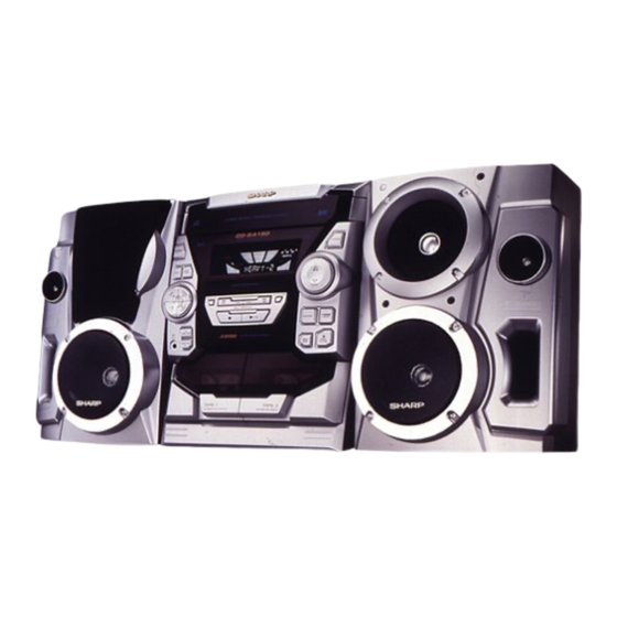
CD-BA150 Mini Component System consisting of CD-BA150
(mini unit) and CP-BA150 (speaker system).
• In the interests of user-safety the set should be restored to its
original condition and only parts identical to those specified be
used.
This document has been published to be used
for after sales service only.
The contents are subject to change without notice.
CD-BA150
No. S1003CDBA150/
Page
Advertisement
Table of Contents

Related Manuals for Sharp CD-BA150


Summary of Contents for Sharp CD-BA150
-
Page 1: Table Of Contents
SERVICE MANUAL No. S1003CDBA150/ CD-BA150 CD-BA150 Mini Component System consisting of CD-BA150 (mini unit) and CP-BA150 (speaker system). • In the interests of user-safety the set should be restored to its original condition and only parts identical to those specified be used. -
Page 2: Important Service Notes (For U.s.a. Only)
CD-BA150 FOR A COMPLETE DESCRIPTION OF THE OPERATION OF THIS UNIT, PLEASE REFER TO THE OPERATION MANUAL. IMPORTANT SERVICE NOTES (FOR U.S.A. ONLY) BEFORE RETURNING THE AUDIO PRODUCT (Fire & Shock Hazard) Before returning the audio product to the user, perform the following safety checks. -
Page 3: Names Of Parts
CD-BA150 NAMES OF PARTS CD-BA150 Front panel (CD) Disc Tray Spectrum Analyzer/Volume Level Indicator Extra Bass Indicator FM Stereo Indicator FM Stereo Mode Indicator (CD) Repeat Indicator Sleep Indicator (CD/TUNER) Memory Indicator (TAPE 2) Record Indicator (CD) Disc Number Indicators... - Page 4 CD-BA150 Rear panel AC Power Input Socket FM/AM Loop Aerial Socket Video/Auxiliary (Audio Signal) Input Sockets Speaker Terminals CP-BA150 Front speaker Tweeter Bass Reflex Duct Woofers Speaker Wire Remote control Remote Control Transmitter LED CD control section Disc Number Select Buttons...
-
Page 5: Operation Manual
CD-BA150 OPERATION MANUAL – 5 –... -
Page 6: Quick Guide
CD-BA150 – 6 –... -
Page 7: Disassembly
CD-BA150 DISASSEMBLY CD-BA150 Caution on Disassembly Follow the below-mentioned notes when disassembling (A1)x2 Top Cabinet the unit and reassembling it, to keep it safe and ensure ø3x12mm excellent performance: 1. Take cassette tape and compact disc out of the unit. - Page 8 CD-BA150 (J2) x1 CLAMP LEVER Turntable CAM GEAR RIB Disc Tray (J1) x2 Figure 8-1 (D1)x2 CD Player Unit ø3x10mm Figure 8-4 (D5)x1 (D2)x2 (D3)x1 Headphones (K1) x3 (D4)x1 (D2)x1 Main PWB (E1)x2 ø3x10mm (K1) x3 Figure 8-2 Figure 8-5...
- Page 9 CD-BA150 Cam Gear (M2) x3 Mechanism Loading Motor (M1) x1 (M1) x1 (N1) x5 Figure 9-1 CP-BA150 STEP REMOVAL PROCEDURE FIGURE Woofer 1. Screw ..... (B1) x8 Tweeter 1. Screw ....(D1) x2 CP-BA150 (D1)x4 ø4x16mm (D1)x4 ø4x16mm Screw Driver...
-
Page 10: Removing And Reinstalling The Main Parts
CD-BA150 REMOVING AND REINSTALLING THE MAIN PARTS TAPE MECHANISM SECTION TAPE2 Perform steps 1 to 5 and 7 of the disassembly method to Record/Playback Head remove the tape mechanism. How to remove the record/playback and erase heads (TAPE 2) (See Fig. 10-1) 1. -
Page 11: Adjustment
CD-BA150 CD MECHANISM SECTION Perform steps 1, 2, 3, 9, 12 and 13 of the disassembly method to remove the CD mechanism. How to remove the loading motor Loading Motor (See Fig. 11-1) 1. Bend the hooks (A1) x 5 pcs., to remove the loading motor. -
Page 12: Tuner Section
CD-BA150 • FM RF TUNER SECTION Signal generator: 1 kHz, 22.5 kHz dev., FM modulated fL: Low-range frequency fH: High-renge frequency Test Stage Frequency Frequency Serring/ Instrument Display Adjusting Connection • AM IF/RF Point Signal generator: 400 Hz, 30%, AM modulated FM Band —... -
Page 13: Notes On Schematic Diagram
CD-BA150 NOTES ON SCHEMATIC DIAGRAM • The indicated voltage in each section is the one measured • Resistor: by Digital Multimeter between such a section and the chas- To differentiate the units of resistors, such symbol as K and sis with no signal given. -
Page 14: Waveforms Of Cd Circuit
CD-BA150 WAVEFORMS OF CD CIRCUIT Stopped Stopped 1999/04/05 17:33:17 CH1=500mV CH3=500mV 500ms/div CH1=500mV CH3=1V CH4=1V 500ms/div DC 10:1 DC 10:1 (500ms/div) DC 10:1 DC 10:1 DC 10:1 (500ms/div) NORM:20kS/s NORM:20kS/s PDO1 IC2 1 IC2 24 PDO2 IC2 2 IC2 23... -
Page 15: Block Diagram
CD-BA150 CLAMP DISC OPEN/ NUMBER CLOSE UP/DOWN MOTOR TO MAIN SECTION TO DISPLAY SECTION (TO IC401) 9 10 75 76 45 46 47 48 32 31 30 LC78641E SERVO/SIGNAL CONTROL CONT5 SLD0 XOUT SPD0 16.9344MHz VDD5V 5 18 36 44 49 50... - Page 16 CD-BA150 FM IF IC301 T302 CF303 TA7358AP BF301 CF351 X351 FM FRONT END 456KHz CF352 T351 AM IF CNP301 AM MIX AM IF MO/ST L312 FM RF T301 IC303 LA1832S FM/AM FM/AM IF MPX. MPXIN FM/AM OSC BUFF FM OSC...
- Page 17 CD-BA150 FL701 FL DISPLAY 29 44 Q601~ Q603 4948 47 59 58 57 55 54 53 52 51 44 43 42 44 SW601~SW603 SW609~SW623 VLOAD IC701 SW625~SW628 SYS. STOP IX0328AW AVDD SYSTEM MICROCOMPUTER JK951 15 16 17 20 21 22...
-
Page 18: Schematic Diagram / Wiring Side Of P.w.board
CD-BA150 CD SERVO PWB-B Vref TIN1 FIN1 0.047 FIN2 TIN2 1.5M LA9235M SERVO AMP. 0.47/6.3 2.2/50 FIN1 100P ODRV FIN2 RFSW 120K 6.8K AGCON TIN1 (CH) 0.01 47/10 TIN2 100/10 REF1 0.01 0.0047 10/16 VREF 0.33 ODRV RFEV PH/BH 100K... - Page 19 CD-BA150 CD SIGNAL 100P 0.01 100P 100P 100P 100P 100P 100P DEFECT 2.2µH EFMO VDD5V 80 79 78 77 76 75 74 72 71 70 69 68 67 66 65 0.047 PD01 COMMAND GENERAL INTERFACE 1.5M 100/10 PD02 SBCK 2.2/50...
- Page 20 CD-BA150 C405 0.022 CNS402 R-CH C404 100/16 A_GND P19 12 - F L-CH C407 CNP11 CD_GND C406 22/50 10/50 VREF TO CD SERVO C408 10/50 INTERFACE C409 R415 LOUT ROUT C410 0.1(ML) 0.1(ML) 3.9K C411 0.1(ML) C412 0.1(ML) LBASS RBASS...
- Page 21 CD-BA150 MAIN PWB-A1(1/3) SO401 22/50 VIDEO/AUX 10/50 R419 C429 R421 R416 L-ch 5.6K 390P (ML) 3.9K 0.1(ML) C430 R420 5.6K 390P R422 0.0027 R-ch 1/50 1/50 1/50 1/50 TUN_R 1/50 R418 TUNER 3.3K TUN_L SECTION 1/50 P25 11 - H...
- Page 22 CD-BA150 IC901 STK40204(2Ch) POWER AMP. –B C901 C902 220P 220P C903 –B R919 R918 R901 R903 C910 100/50 C906 R906 C905 R931 47/50 47/50 –B C916 0.047 R934 (ML) R933 C935 10/50 R907 C915 0.1(1W) R908 D901 0.047(ML 0.1(1W) DS1SS133...
- Page 23 CD-BA150 R975 CNS971 CNP971 4.7(1/2W) C971 47/50 FM SIGNAL D971 4.9V R971 M901 DS1SS133 FAN MOTOR Q971 KTC3203 Y R973 C972 R972 10/50 RL951 RELAY R953 R954 4.7K 4.7K FW951 CNS951 R952 330(1/2W) R951 JK951 330(1/2W) HEADPHONES D951 Q951 HEADPHONES PWB-A3...
- Page 24 CD-BA150 C302 0.001 C330 AM TRACKING 15P(UJ) C331 0.047 C323 0.022 C338 0.001 T303 C332 D301 DS1SS133 0.022 R365 D302 DS1SS133 VD301 AM BAND C335 SVC348S COVERAGE R358 560P T306 3.9K C334 R336 R323 AM OSC (UJ) BF301 B.P.F IC301...
- Page 25 CD-BA150 R363 C373 R364 0.015 C371 R361 1/50 R350 2.7K C367 R362 C372 1/50 1/50 C369 (UJ) 20 19 18 17 16 15 14 13 IC303 LA1832S FM IF DET./FM MPX./AM IF C358 1/50 R352 R353 C357 R355 2.2/50 3.3K C356 0.001...
-
Page 26: Notes On Schematic Diagram
CD-BA150 DISPLAY PWB-A2 FL701 FL DISPLAY 49 48 47 44 43 42 41 39 38 37 36 35 34 33 32 31 30 29 28 27 26 25 24 23 16 15 14 13 12 11 10 9 8 7 6 3 2 1... - Page 27 CD-BA150 24 23 16 15 14 13 12 11 10 9 8 7 6 3 2 1 CD INT WRQ(DSP) P19 12 - F CD CE CD SERVO PWB CD DO CD DI CNP12 CD CLK RES OUT CLAMP SW...
- Page 28 CD-BA150 DISPLAY PWB P30 4 - H CNP702 CNS402 P32 4 - A TO CD SERVO FC701 CNP11 R423 Q110 R142 C138 C423 R132 R136 R139 C134 C425 R124 R140 R141 C132 C144 C427 C131 C136 IC401 R134 R135 R418...
- Page 29 CD-BA150 MAIN PWB-A1 R378 R374 X352 R372 R388 R373 C382 R409 C395 IC302 C381 R376 C387 R379 12 1314 1516 17 1819 20 21 22 R377 L351 C392 C394 Q360 C380 R375 HEADPHONES R381 R382 C393 PWB-A3 ZD351 C404 T301...
- Page 30 CD-BA150 P32 4 - A TO CD SERVO PWB CNP12 CNS701 FL701 BI701 D609 D608 D607 C616 SW601 POWER IC701 R634 R696 R647 R635 R700 R633 SW602 R629 CLOCK R632 SW603 R669 R661 TIMER/ SLEEP R670 R673 IC704 R653 L601...
- Page 31 CD-BA150 DISPLAY PWB-A2 RX701 C609 C631 R601 C632 R621 R611 R606 Q601 R616 SW611 DIMMER Q602 SW614 IC701 VOLUME R679 R680 D604 Q603 DZ601 C614 C622 R612 C611 C623 C603 R609 R620 IC703 C608 R619 R625 R605 R615 D601 R610...
- Page 32 CD-BA150 P28 5 - A P30 2 - A TO MAIN PWB TO DISPLAY PWB CNS402 CNS701 CD SERVO PWB-B 9 10 CNP11 CNP12 E C B ZD61 B C E CNP1 40 41 1 2 3 CNP4 CNP3 CNS3A...
- Page 33 CD-BA150 P31 9 - H TAPE MECHANISM TO DISPLAY PWB ASSEMBLY CNP702 FC702 TAPE MECHANISM PWB-D SOLENOIDE SOLENOIDE TAPE 2 TAPE MOTOR TAPE 1 ERASE HEAD RECORD/PLAYBACK PLAYBACK HEAD HEAD TO MAIN PWB P28 2 - E CNS802 PT801 1 2 3 4 5 6 7 8...
-
Page 34: Voltage
CD-BA150 VOLTAGE IC101 IC901 IC701 IC303 PIN VOLTAGE NO. VOLTAGE NO. VOLTAGE NO. VOLTAGE NO. VOLTAGE VOLTAGE NO. VOLTAGE 1.6V 0.7V 5.0V 4.29V 0V (0V) 2.1V (2.4V) 1.6V 0V (0V) 4.29V 4.5V (4.8V) 1.6V 5.0V 4.29V 0.5V (0.5V) 2.1V (2.1V) 1.6V... -
Page 35: Troubleshooting (Cd Section)
CD-BA150 TROUBLE SHOOTING When the CD does not function When the CD section does not operate when the objective lens of the optical pickup is dirty, this section may not operate. Clean the objective lens, and check the playback operation. When this section does not operate even after the above step is taken, check the following items. - Page 36 CD-BA150 (1) Focus-HF system check Stopped CH1=500mV CH3=500mV 500ms/div Although a CD is inserted and the cover is closed, "NO DC 10:1 DC 10:1 (500ms/div) NORM:20kS/s DISC" is displayed. Press the OPEN/CLOSE switch (SW1) without inserting a disc, and try starting the playback operation.
- Page 37 CD-BA150 (2) Tracking system check Check the TE waveform at pin 18 on IC1. The tracking servo is not activated. If the waveform shown in Figure 37-1 appears and soon after Check the peripheral circuits at pins 18 and 19 on IC1, pin 23 on NO DISC appears.
- Page 38 CD-BA150 (4) PLL system check Stopped 1999/04/05 17:33:17 CH1=500mV CH3=1V CH4=1V 500ms/div DC 10:1 DC 10:1 DC 10:1 (500ms/div) NORM:20kS/s When a disc is loaded, start play operation. PDO1 The HF waveform is normal, but the TOC data cannot be PDO2 read.
-
Page 39: Function Table Of Ic
CD-BA150 FUNCTION TABLE OF IC IC1 VHiLA9235M/-1: Servo Amp. (LA9235M) ODRV FIN1 LA9235M RFSW FIN2 AGCON 28 RF- FIN3 FIN4 26 N/C 25 PH 24 BH REF1 ODRV 23 N/C PH/BH 22 RFEV VREF 21 FE- 20 FE LDOF 19 TE-... - Page 40 CD-BA150 IC2 VHiLC78641E-1: Servo/Signal Control (LC78641E) (1/2) Terminal Name Input/Output Setting in Reset Function Pin No. PDO1 Output – For PULL Phase-comparison output terminal for built-in VOC control. PDO2 Output – Phase-comparison output terminal for built-in VOC control. Rough servo : OFF, phase servo : ON.
- Page 41 CD-BA150 IC2 VHiLC78641E-1: Servo/Signal Control (LC78641E) (2/2) Terminal Name Input/Output Setting in Reset Function Pin No. LVDD – – L channel Power terminal for L channel. LCHO Output 1/2VDD D/A converter L channel output terminal. LVSS – – Ground terminal for L channel. Surely connected to 0V.
- Page 42 CD-BA150 IC701 RH-iX0328AWZZ: System Microcomputer (IX0328AW) (1/2) Pin No. Port Name Terminal Name Input/Output Function — (+) POWER SUPPLY — — S-BUSY Output COMMIJNTCATE TO MPEG U–COM T–BTAS Output TAPE RECORD BIAS T–T1/T2 Output TAPE T1/T2 CHANGE REC/PLAY Output TAPE REC/PLAY CHANGE...
- Page 43 CD-BA150 IC701 RH-iX0328AWZZ: System Microcomputer (IX0328AW) (2/2) Pin No. Port Name Terminal Name Input/Output Function P120 PLAY SW_B Input PLAY SWITCH FOR T2 P119 Input TAPE2 A–SIDE FULL PROOF P118 Input TAPE2 B_SIDE FULL PROOF P117 MIC SW Input MIC SWITCH...
- Page 44 CD-BA150 IC401 VHiLC75341/-1: Audio Processor (LC75341) ROUT LOUT LBASS RBASS 0.1uF 0.1uF LTRE RTRE LSEL0 RSEL0 R1 R2 24 23 22 21 20 19 18 17 16 15 14 13 LC75341 10 11 12 Figure 44 BLOCK DIAGRAM OF IC...
-
Page 45: Fl Display
CD-BA150 FL701 VVKBJ749GNK-1: FL Display B7 B6 B5 B4 B3 B4 B5 B6 B7 Figure 45 FL DISPLAY – 45 –... - Page 46 CD-BA150 — M E M O — – 46 –...
-
Page 47: Parts Guide
CD-BA150 PARTS GUIDE CD-BA150 MODEL CD-BA150 Mini Component System consisting of CD-BA150 (mini unit) and CP-BA150 (speaker system). “HOW TO ORDER REPLACEMENT PARTS” To have your order filled promptly and correctly, please furnish the For U.S.A. only following information. Contact your nearest SHARP Parts Distributor to order. - Page 48 CD-BA150 PRICE PRICE PARTS CODE DESCRIPTION PARTS CODE DESCRIPTION RANK RANK FILTERS CD-BA150 INTEGRATED CIRCUITS BF301 RFILR0008AWZZ AE Band Pass Filter CF303 RFILF0124AFZZ AD FM IF,10.7 MHz CF351 RFILF0003AWZZ AK FM IF VHILA9235M/-1 AQ Servo Amp.,LA9235M CF352 RFILA0009AWZZ AE AM IF...
- Page 49 CD-BA150 PRICE PRICE DESCRIPTION PARTS CODE DESCRIPTION PARTS CODE RANK RANK AA 0.047 µF,50V AB 100 µF,10V,Electrolytic C101 VCKZPA1HF473Z C396 VCEAZA1AW107M J AA 0.001 µF,50V AA 0.022 µF,25V C102,103 VCKYMN1HB102K J C397 VCTYMN1EF223Z AB 100 µF,10V,Electrolytic C104,105 VCKYMN1HB181K J AA 180 pF,50V...
- Page 50 CD-BA150 PRICE PRICE PARTS CODE DESCRIPTION PARTS CODE DESCRIPTION RANK RANK R12,13 VRS-TV2AB681J AA 680 ohms,1/10W R357 VRD-ST2CD474J AA 470 kohms,1/6W VRS-TV2AB122J AA 1.2 kohms,1/10W R358 VRD-ST2CD392J AA 3.9 kohms,1/6W VRS-TV2AB103J AA 10 kohm,1/10W R359 VRD-MN2BD182J AA 1.8 kohms,1/8W VRD-ST2CD103J...
- Page 51 CD-BA150 PRICE PRICE DESCRIPTION PARTS CODE DESCRIPTION PARTS CODE RANK RANK R662 VRD-MN2BD103J AA 10 kohm,1/8W CNP971 92LCONE2P53253 J AB Plug,2Pin R663~665 VRD-ST2CD222J AA 2.2 kohms,1/6W CNS1A/B QCNWN1537AWZZ J AG Connector Ass’y,7/7Pin R666 VRD-MN2BD102J AA 1 kohm,1/8W CNS2A/B QCNWN1538AWZZ J AG Connector Ass’y,8/8Pin...
- Page 52 CD-BA150 PRICE PRICE PARTS CODE DESCRIPTION PARTS CODE DESCRIPTION RANK RANK 92LPT0311101 AB Lever,Clamp CABINET PARTS 92LPT0311102 AC Lever,Disc 92LPT0312005 Gear,Cam 92LCAB3283AASY J Front Cabinet Ass’y 92LPT0320201 AE Support,Stabilizer 201- 1 ———— –– Front Panel 92LPT0330301 AU Chassis,Loading (Not Replacement Item)
- Page 53 CD-BA150 PRICE DESCRIPTION PARTS CODE RANK OTHER SERVICE PARTS UDSKA0004AFZZ AZ CD Pickup Lens Cleaner CP-BA150 SPEAKER BOX PARTS 92L126-0009 BA Front Panel Ass’y,Left 92L126-0010 BA Front Panel Ass’y,Right 92L121-0178 AP Net Frame Ass’y 92L051-0079 Speaker Box Ass’y,Left 92L051-0085 Speaker Box Ass’y,Right...
- Page 54 CD-BA150 CD-BA150 306-2 306-1 306-3 703x4 305x2 PWB-C Figure 7 CD MECHANISM EXPLODED VIEW – 7 –...
- Page 55 CD-BA150 CD-BA150 PWB-A1 202-1 610x2 609x2 610x2 617x9 614x3 IC901 614x2 607x3 Q831 Silicon 202-2 IC901 231x6 grease 615x15 PWB-A2 BELT CONNECTION FF/REW FF/REW IC841 ROLLER ROLLER ASS'Y ASS'Y 201-13 201-14 201-15 FLYWHEEL FLYWHEEL 201-12 201-21 ASS'Y ASS'Y MAIN BELT...
- Page 56 CD-BA150 CD-BA150 604x2 604x2 MECHANISM 250x4 PWB-E 239x3 204-2 204-1 204-3 PWB-B Figure 9 CABINET EXPLODED VIEW (2/2) – 9 –...
- Page 57 CD-BA150 CP-BA150 (with Capacitor C1,2) 904,905 914x4 914x4 913x2 912x4 901,902 907x4 C1,2 Capacitor TWEETER 3.3µF,100V C1,2 Capacitor 3.3µF,100V Electrolytic WOOFER WOOFER Figure 10 SPEAKER EXPLODED VIEW – 10 –...
-
Page 58: Packing Of The Set (For U.s.a. Only)
CD-BA150 PACKING OF THE SET (FOR U.S.A. ONLY) Setting position of switches and knobs Tape Mechanism STOP UNIT FRONT SPEAKER CP-BA150 92L411-0075 SPAKP0013AWZZ1 Polyethylene Bag Polyethylene Bag, Unit SPAKA0235AWZZ Packing Add., Left/Right Bottom 92L412-0133 Packing Add. TLABZ0670AWZZ Label, Feature Tape2... - Page 59 CD-BA150 –– MEMO –– – 12 –...
- Page 60 CD-BA150 © COPYRIGHT 2000 BY SHARP CORPORATION ALL RIGHTS RESERVED. No part of this publication may be reproduced, stored in a retrieval system, or transmitted in any from or by any means, electronic, mechanical, photocopying, recording, or otherwise, without prior written permission of the publisher.