
Related Manuals for Philips Dica 220


Summary of Contents for Philips Dica 220
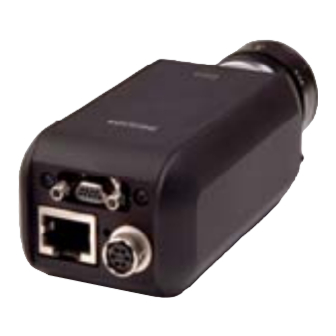
- Page 1 Industrial Vision Dica 220 Digital Camera 12NC : 8122 410 5904.0 Hardware Manual Philips Applied Technologies...
- Page 2 The information in this publication is furnished for guidance, and with no guarantee as to its accuracy or completeness. Philips Applied Technologies does not assume liability for any consequences of its use; specifications and availability of goods mentioned in it are subject to change without notice.
-
Page 3: Table Of Contents
CONTENTS INTRODUCTION............................1 ABOUT THIS MANUAL .............................. 1 SUPPLIED PARTS..............................1 ABOUT THE INSTALLATION ............................ 1 HARDWARE .............................. 2 10BaseT/100BaseT..............................2 TRIGGER AND FLASH .............................. 3 I/O CONNECTOR ..............................4 2.3.1 Power supply ................................4 2.3.2 External Reset ................................4 2.3.3 RS232.................................. - Page 4 KNOWN PROBLEMS USING THE DICA......................... 13 SUPPORT CHANNELS............................13 TECHNICAL SPECIFICATION ........................14...
-
Page 5: Introduction
• Rhapsody device for embedded programming. • Clicks device. The Dica 220 is a digital camera that is able to capture and • Promise device. transfer images via a Ethernet connection to a PC. This can be done with an installed Rhapsody (v3.0 or newer), ABOUT THIS MANUAL Promise ( v3.6 or newer ) or Clicks (v1.9 or newer) -
Page 6: Hardware
• equipped with an Ethernet Controller. Trigger input and flash outputs • To connect one single Dica 220 directly to a PC, only a I/O connector UTP cross cable is required. In order to be able to control • CMOS sensor multiple Dica 220 cameras adequate knowledge of how an •... -
Page 7: Trigger And Flash
TRIGGER AND FLASH The Dica 220 has one optically isolated trigger input and Function two optically isolated flash outputs. See chapter 6 for the Trigger Ground electrical details. Trigger input The trigger input enables the feature that an image capture Flash 1 output is started by a hardware signal (the trigger input). -
Page 8: I/O Connector
Power supply power supply • system reset function The Dica 220 is powered by connecting the external power • RS232 pin 1 to the + pole and pin 6 to the ground of a power supply. The voltage must be in the range 10..24 volts, but Check our website for available accessories that can be is typically 24 Volt. -
Page 9: Cmos Sensor
During the production • 10 bit 40 MHz sample ADC resolution of the Dica 220 special account is taken with respect to the • 2/3” sensor cleanness of the sensor. However when you remove the •... -
Page 10: Powering Up
IP number that needs to be set results in a conflict on the network. Factory default a for this). After completion the downloaded program Dica 220 has device ID 1, resulting in the IP address starts execution. 192.168.10.1. - Page 11 illuminate green. If after this test the System LED is blinking red, check chapter 5 for possible causes. For a more detailed description of the System LED, check the User Manual of the supporting software packages. 2005-06-27 Page 7...
-
Page 12: Software Installation
To start using the Dica 220 you can select one of the camera. If the camera is configured to run a Clicks- following software products that can be obtained... -
Page 13: Ethernet Configuration
The second option allows you to fill in the IP address when camera and other Dica 220 cameras to a PC or it can be DHCP is not used. part of a much larger existing network with multiple PCs... - Page 14 The format of this file is as follows: Devices Sometimes a camera cannot be automatically detected by [HOST] a host PC e.g. when the camera is outside of the LAN or Domain = dddd when broadcasting is disabled. In these cases, the detection of a camera can be forced by specifying the [DEVICES] device ID, the camera type and its IP address.
-
Page 15: Firewall
The password for a given camera can also be globally set in the RapEthernet.ini file. It is a 32 bit number which is Broadcasting Enabled specified in 8 hexadecimal digits (leading zeros can be DHCP enabled discarded). The default password is 0, which implies using Auto IP disabled no password at all. -
Page 16: Mechanical Interface
(the two M3x5 screw holes). 47.0mm. Ø28 mm H7 2/3" CMOS sensor 21.0 C-mount M 23.2 M3 x 5mm 28.0mm. 2x M3 x 5 Figure 4-2: Dica 220 bottom view 21.0mm. Figure 4-1: Dica 220 front view Page 12 2005-06-27... -
Page 17: Trouble Shooting
When the sensor protection cap is removed from the Dica 220 front end prior to the mounting of the lens, the sensor can attract some dust or dirt. This can affect the quality of the image captured with the Dica 220. - Page 18 Maximum Baudrate: 115200 Regions of interest Exposure time programmable up to 65535 µs. Environmental Frame rate Grabber-Mode: 4 frames per Dica 220 complies to: second (at 100Mbs) EFT immunity: IEC1000-4-4 Embedded: 27 frames per ESD immunity: IEC1000-4-2 / EN50082-2 second...