Motorola StarTAC 3000 Service Manual
Hide thumbs
Also See for StarTAC 3000:
- Owner's manual (96 pages) ,
- User manual (108 pages) ,
- Manual (10 pages)

Related Manuals for Motorola StarTAC 3000


Summary of Contents for Motorola StarTAC 3000
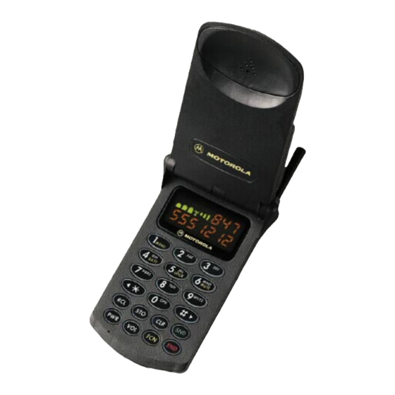
- Page 1 StarTAC 3000 Cellular Subscriber Sector The World’s Leading Cellular Telephone Manufacturer Service Manual Level III...
- Page 2 Motorola products shall not be deemed to grant either directly or by implication, estoppel, or otherwise, any license under the copyrights, patents or patent applica- tions of Motorola, except for the normal non-exclusive, royalty free license to use that arises by operation of law in the sale of a product.
-
Page 3: Preface
+ 2.9 kHz deviation (nom.) @ 97 dB SPL input @ 1 kHz NAMPS: +1.5 kHz deviation (nom.) @ 97 db SPL input @ 1 kHz Receive Sensitivity -116 dBm for 12 dB SINAD (C-MSG weighted) © 1998 Motorola, Inc. - Page 4 StarTAC 3000 Table 1: General Function Specification Alternate Channel De-sense Protection -60 db @ +60 kHz Table 2: Environmental Function Specification Temperature Range Operational C to +60 C (-22 F to +140 Storage C to +85 C (-67 F to +185...
-
Page 5: Forward
Support Centers offer some of the finest types of equipment. It is intended primarily repair capabilities available to Motorola to support basic servicing, which consists Subscriber equipment users. The Cellular primarily of mechanical repairs and circuit Subscriber Support Centers are able to board replacement. -
Page 6: General Safety Information
StarTAC 3000 General Safety Information DO NOT operate this equipment near elec- trical blasting caps or in an explosive atmo- sphere. Mobile telephones are under certain conditions capable of interfering with Portable Operation blasting operations. When in the vicinity of... -
Page 7: Table Of Contents
TX Power Out Test ..... 24 TX VCO ......B-8 © 1998 Motorola, Inc. - Page 8 StarTAC 3000 PA Circuit ......B-9 RF Detect Circuit ..... B-10 Pacer IC U601 .
-
Page 9: Theory Of Operation
MHz first IF signal. The IF signal passes is employed in both AMPS and NAMPS through a crystal filter and then enters the modes. Low Voltage ZIF IC. The LVZIF IC contains a 219.3MHz second This circuit achieves better than 1.0 ppm © 1998 Motorola, Inc. -
Page 10: Transmitter Circuits
StarTAC 3000 frequency error, using the received signal as The SNAP IC compares the Power Detect the frequency reference. The logic section voltage to a reference voltage and sends a monitors the Frequency Error signal and Power Control signal back to the PA. The... -
Page 11: Special Logic Circuits
• PAC IC —A triple 8 bit DAC that controls the PA bias and internal charger • Internal Charger —The microprocessor is capable of reading a Motorola Li Ion battery with internal ROM to determine optimum charging conditions. If no ROM is detected, then the battery is charged as if it were a NiCd or NiMH battery. - Page 12 StarTAC 3000 6/29/98...
-
Page 13: Manual Test Mode
first digit of the • Tx audio state phone number is entered. The telephone number is displayed in the normal manner as entered. When the Snd button (or End or Clr ) is pressed, the status information display resumes. © 1998 Motorola, Inc. -
Page 14: Servicing Level
StarTAC 3000 Figure 2: Status Display Indicator Blank Channel Number RSSI Reading Transmit Audio Path SAT Frequency (voice channel) (Voice Channel) 0=5970 Hz, 1=6000 Hz, 2=6030 Hz Busy/Idle Digital Color Code (data channel) (data channel) 0-3=Valid codes, 4=invalid code 0 = enabled/busy... -
Page 15: Test Commands
Manual Test Mode Test Commands Each command consists of at least two digits entered from the telephone keypad with the entry terminated using the # key. If the command relates to a test function with multiple data displays, the * key is used to pause scanning data or to step through sequential test functions. - Page 16 StarTAC 3000 Table 3: Test Commands For Manual Test Mode Keypad Command Status Result Entry Description Display INIT Initialize the radio as follows: 1. Carrier = OFF 2. Power Level = 0 3. Receive Audio = MUTED 4. Transmit Audio = MUTED 5.
- Page 17 Manual Test Mode Table 3: Test Commands For Manual Test Mode Keypad Command Status Result Entry Description Display NOTE: Entering commands 20# through 23# or 27# causes the transceiver to begin a counting sequence or continuous transmission as described below. The # key must be depressed to exit the command;...
- Page 18 StarTAC 3000 Table 3: Test Commands For Manual Test Mode Keypad Command Status Result Entry Description Display 25A# SAT/DSAT ON Enable the transmission of SAT when A = SAT frequency or DSAT code. Wide call processing mode: SAT Freq. 5970 Hz...
- Page 19 Manual Test Mode Table 3: Test Commands For Manual Test Mode Keypad Command Status Result Entry Description Display DTMFOFF De-activate DTMF tone. 35A# AUDIO-PATH Change the audio path to A, where A =: 0 = Hands free (selects input signal AUDIO IN @ J3- pin 8 and outputs audio signal AUDIO OUT/ON- OFF @ J3-pin 7;...
- Page 20 StarTAC 3000 Table 3: Test Commands For Manual Test Mode Keypad Command Status Result Entry Description Display RCVVC Receive one voice channel word (wide mode only). When the word is received it is displayed in hex. This command will be complete when a voice channel word is received or when the # key is entered to abort the command.
- Page 21 Manual Test Mode Table 3: Test Commands For Manual Test Mode Keypad Command Status Result Entry Description Display MODEL TYPE Read model type. Display three radio model bytes: hardware (model), flex (type), and factory. ID TRANSFER Reserved for Identity Transfer Procedure. 70# &...
- Page 22 StarTAC 3000 6/29/98...
-
Page 23: Nam Programming
NAM. In most cases, the number Table 4, “Minimum Required Test Mode of digits displayed and the default value NAM Programming Steps” below, shows displayed identify the current programming the minimum required Test Mode NAM step number. programming steps. © 1998 Motorola, Inc. -
Page 24: User Mode Programming
StarTAC 3000 If a second phone number is to be Some models may be available with a User programmed, step 11 bit 6 must be set to 1. Mode Programming manual which This bit enables dual-NAM operation and describes the entry key sequences and the... -
Page 25: Test Mode Nam Programming Sequence
NAM Programming Test Mode NAM Programming Sequence Advances to the next programming step; also programs the NAM after the last programming step is entered. Clears the entered information and displays previously entered data for the current programming step. Exits the programming mode without programming the NAM. Table 5: Test Mode NAM Programming Sequence Factory Step... - Page 26 StarTAC 3000 Table 5: Test Mode NAM Programming Sequence Factory Step Description Default Systems group ID mark. Specifies how many bits of the system ID are compared during call processing. Assigned by system operator. 000000 Security code. A 6 digit number supplied by the user. This number is used by the user to access or change “security”...
- Page 27 NAM Programming Table 5: Test Mode NAM Programming Sequence Factory Step Description Default 00000000 C OPTION BYTE The display for step 11 represents the status of eight options, C7 through C0. C7 (msb) is programmed first followed by C6-C0. Bits enter display on the right and scroll left. User Mode NAM Programming Disable (Bit C7).
- Page 28 StarTAC 3000 6/29/98...
-
Page 29: Testing And Adjustments
Turn on compandor 356# Select external RX audio path 474# Set volume control to level 4 Refer to the RX troubleshooting section for 356# Set RX audio path to Ext. Audio- Path radios not within specifications. © 1998 Motorola, Inc. -
Page 30: Tx Power Out Test
StarTAC 3000 TX Power Out Test Check the FM deviation for the reading. Refer to the TX troubleshooting section for radios not within the pass specifications. Communications Analyzer Setup: HP8920 Screen: TX with dBm selected TX Audio Distortion Test TX Frequency: 834.99 MHz (ch. 333) -
Page 31: Tx Sat Deviation Test
Testing and Adjustments Turn on transmit carrier TX DSAT Deviation Test 356# Select External TX Audio path Unmute TX Audio path Communications Analyzer Setup: Turn on compandor HP 8920 Screen: TX Pass Specifications: .630 kHz -.770 kHz TX SAT Deviation Test Test Mode Commands: Communications Analyzer Setup: 571#... -
Page 32: Tx Output Power Adjust
The 73# command is normally disabled. a. Depress the CLR button and Adjustment of Transmit Output Power is not recommended. Consult Motorola for enter another 2-digit number information about enabling the 73# Transmit Power Adjustment Procedure. -
Page 33: Maximum Deviation Adjust
Testing and Adjustments 46#061010# Turns the display and backlight on. NOTE In order to enter hex digits A thru F, Maximum Deviation Adjust depress the SND button followed by: hex A NOTE hex B Before SAT, DSAT, DTMF, data, or micro- hex C phone deviations can be adjusted, the hex D... -
Page 34: Microphone Deviation Adjust
StarTAC 3000 Step 13. Repeatedly depress the] key until Step 23. Enter 11816# to place the telephone the display shows the ’ prompt. on channel 816. Enter 72# and press the ] key four times to advance to Step 14. Enter 11211# to place the telephone step 04. -
Page 35: Dtmf Deviation Adjust
Testing and Adjustments Step 29. Enter 72# , use the ] button to toggle Step 34. Read the average deviation on the down to step 06 (left side of communications analyzer. display), and enter the step 05 hex value noted in step 26. If the reading is 1.4 kHz + 10% (corresponds to 2.0 kHz peak), Exit... -
Page 36: Dsat Deviation Adjust
StarTAC 3000 DSAT Deviation Adjust Step 48. Enter 72# , use the ] button to toggle down to step 0A (left side of display), and use the volume Step 39. Enter 571# to place the phone in control or enter numbers from 00 to narrow channel test mode. -
Page 37: Disassembly
• Anti-Static Mat Kit (RPX-4307A); includes: damaging or stressing the housing and internal components. Motorola recommends — Anti-Static Mat 66-80387A959 the use of a properly grounded high imped- — Ground Cord 66-80387A989... - Page 38 StarTAC 3000 Antenna Removal Step 1. Turn off the telephone. Step 2. Press down on the battery’s tab and remove the battery from the housing. Step 3. Use the antenna tool to remove the antenna. Place the wide tip of the...
- Page 39 Disassembly Opening Housing Step 1. With flat surface of tool facing up, insert housing opener at a 45º angle. Make sure you can see top of tool in seam. Step 2. Press push corner outwards with left thumb while right hand twists phone like a rag.
- Page 40 StarTAC 3000 Step 4. Using plastic disassembly tool, slide the tool under the housing all the way to corner and lift housing off corner. Step 5. With flat surface of tool facing up, insert housing opener at a 45º angle. Make sure you can see top of tool in seam.
- Page 41 Disassembly Board Removal Step 1. Open the flex connector and pull out the flex. Step 2. With your thumbs, pry the side tabs away from the board assembly to allow it to be easily removed. Starting at the top of the board, lift board...
- Page 42 StarTAC 3000 Step 4. Lift and separate the display audio-logic board assembly from transceiver board. To disconnect display board from audio-logic board, open flex connector and remove flex. The keypad easily lifts out of the front housing. 6/29/98...
- Page 43 Disassembly Flip Removal Step 1. Using the the pointed end of the plastic dissassembly tool, pry off the left side of the cover. Step 2. Using the point end of the plastic prying tool insert it on the right side of the locking tab.
- Page 44 StarTAC 3000 Speaker/Vibrator Removal Step 1. Rest flip housing on a flat surface. Slip a dental pick between front housing and battery contacts. Pry up to unsnap front housing battery contacts. The speaker, vibrator, and flex should be exposed. 6/29/98...
-
Page 46: Section A
Section A StarTAC 3000 Mechanical Parts List Description Part# SWF3006H SWF3165H FRONT HOUSING 1509418J11 BACK HOUSING 1509403T02 FLIP FRONT HOUSING 1509076K17 FLIP REAR HOUSING 1509214B02 DISPLAY 7209375K05 LENS 6109126K01 KEYPAD 3809127K02 FLEX BARREL 1509077K02 SPEAKER DISH 1509101C02 FLEX LABEL 5409354E01 HINGE ASSY. - Page 47 StarTAC 3000 MAIN BOARD SIDE 2 Reference Reference Reference Part# Designator Designator Designator Part# Part# R00996 0609591M25 C00655 2309121D30 R01004 0609591M37 C00671 2311049A07 R00608 0611079A02 C00610 2311049A63 R00674 0660076N45 C00607 2311049A89 R00634 0660076N55 C00871 2311049A89 R00999 0660076S01 C00622 2311049A89 R00609...
- Page 48 StarTAC 3000 MAIN BOARD SIDE 1 Reference Reference Reference Part# Part# Designator Designator Part# Designator RV0667 0609118R01 R00519 0662057M98 C00202 2113741F49 RV0668 0609118R01 R00520 0662057M98 C00204 2113741F49 R00574 0609591M37 R00551 0662057M98 C00205 2113741F49 R00560 0660076A11 R00532 0662057M98 C00214 2113741F49 R00502...
- Page 49 StarTAC 3000 MAIN BOARD SIDE 1 Reference Reference Reference Part# Designator Designator Designator Part# Part# C00514 2113743N07 C00576 2113743N40 L00108 2462587N62 C00313 2113743N08 C00058 2113743N40 L00202 2462587P13 C00518 2113743N09 C00059 2113743N40 L00052 2462587V24 C00511 2113743N10 C00641 2113743N40 L00050 2462587V25 C00513...
- Page 50 StarTAC 3000 MAIN BOARD SIDE 1 Reference Reference Reference Part# Part# Designator Designator Part# Designator FL0102 9109617M01 FL0100 9109808M10 FL0201 9109833L01...
- Page 51 StarTAC 3000 AUDIO LOGIC BOARD SIDE 1 Reference Reference Reference Part# Designator Designator Designator Part# Part# R00811 0609591M37 R01042 0662057N23 Q00821 4809579E02 R00801 0609591M49 R01052 0662057N23 Q00680 4809579E24 R00922 0660076A01 R01053 0662057N23 Q00901 4809579E28 R01061 0660076N01 R01054 0662057N23 Q00902 4809579E28...
- Page 52 StarTAC 3000 AUDIO LOGIC BOARD SIDE 2 Reference Reference Reference Part# Part# Designator Designator Part# Designator S00970 4082635T14 DS0970 4809496B11 DS0971 4809496B11 DS0972 4809496B11 DS0973 4809496B11 DS0974 4809496B11 DS0975 4809496B11...
-
Page 53: Service Diagrams
Service Diagrams - Section B StarTAC 3000 Cellular Subscriber Group Service Diagrams service diagrams were carefully prepared to allow a Motorola certified tech- nician to easily troubleshoot cellular phone failures. Our professional staff provided directional labels, color coded traces, measurement values and other guidelines to help a technician troubleshoot a cellular phone with speed and accuracy. - Page 54 StarTAC 3000 6/29/98...
-
Page 55: Rf Switch
RF Switch This manual is Motorola property. Copying or Channel: 385 distribution strictly prohibited without prior written TX Freq: 836.55MHz consent from Motorola and must be returned upon TX Power Level 2 Motorola's request. RX Input Freq: 881.55MHz RX Input: -20dBm... -
Page 56: Rf Amp- Mixer-If
FL102 881.55MHz -26.5dBm RX VCO L312 page B-5 This manual is Motorola property. Copying or distribution strictly prohibited without prior written consent from Motorola and must be returned upon 991.20MHz 881.55MHz Motorola's request. 991.20MHz -12.7dBm -26.5dBm -17.2dBm Motorola Confidential Proprietary... -
Page 57: Rx Vco
StarTAC 3000: RX VCO This manual is Motorola property. Copying or distribution strictly prohibited without prior written consent from Motorola and must be returned upon Motorola's request. Channel: 385 VCO Freq: 991.2MHz Motorola Confidential Proprietary VCO SIGNAL VOLTAGE SUPPLIES Colored boxes represent the area in which the components are placed. - Page 58 StarTAC 3000 : U201 LVZIF IC This manual is Motorola property. Copying or distribution strictly prohibited without prior written consent from Motorola and must be returned upon C231 Motorola's request. Motorola Confidential Proprietary 4.2MHz page B-7 REF 2.75 page B-12...
-
Page 59: U401 Anguss Ic
B-12 RX VCO FEEDBACK This manual is Motorola property. Copying or C313 distribution strictly prohibited without prior written C404 page B-5 consent from Motorola and must be returned upon Motorola's request. RX VCO STEER Motorola Confidential Proprietary R403 page B-5... -
Page 60: Tx Vco
L505 4dBm U502 C514 C512 C526 C507 L503 TX VCO FEEDBACK U401-27 page B-7 This manual is Motorola property. Copying or distribution strictly prohibited without prior written consent from Motorola and must be returned upon Motorola's request. Motorola Confidential Proprietary... -
Page 61: Pa Circuit
StarTAC 3000 : PA Circuit This manual is Motorola property. Copying or distribution strictly prohibited without prior written Power Level consent from Motorola and must be returned upon Motorola's request. 1.38V 1.3V 1.21V 1.2V 1.07V .924V 836.55MHz 3.11V 3.23V 3.34V 3.43V 3.49V 3.55V... -
Page 62: Rf Detect Circuit
RF Detect Circuit FL504 This manual is Motorola property. Copying or Power Level distribution strictly prohibited without prior written consent from Motorola and must be returned upon Motorola's request. .954V .637V .435V .241V .159V .11V Motorola Confidential Proprietary J800 RFDET... -
Page 63: Pacer Ic U601
This manual is Motorola property. Copying or page B-15 J800 distribution strictly prohibited without prior written VOLTAGE SUPPLIES ON OFF consent from Motorola and must be returned upon R990 Motorola's request. Colored boxes represent the area in page B-15 which the components are placed. -
Page 64: Voltage Regulators
NEG_BIAS U601-32 page B-11 U610 L601 This manual is Motorola property. Copying or distribution strictly prohibited without prior written consent from Motorola and must be returned upon Motorola's request. VOLTAGE SUPPLIES Colored boxes represent the area in Motorola Confidential Proprietary... -
Page 65: B+ Supply
Colored boxes represent the area in which the components are placed. BATT+ This manual is Motorola property. Copying or distribution strictly prohibited without prior written page B-24 consent from Motorola and must be returned upon Motorola's request. Motorola Confidential Proprietary... -
Page 66: Charger/Thermistor/Bat Ser Dat
StarTAC 3000: Charger/Thermistor Bat Ser Dat VR691 VOLTAGE SUPPLIES Colored boxes represent the area in which the components are placed. U601-46 page B-11 CR670 VR692 P800 AUDIO OUT/ON OFF R990 page B-22 J3-9 J800 page B-24 THERMISTER SENSE U800-28 R642... -
Page 67: Keypad Matrix
Keypad Matrix This manual is Motorola property. Copying or distribution strictly prohibited without prior written Colored boxes represent the area in consent from Motorola and must be returned upon which the components are placed. Motorola's request. Motorola Confidential Proprietary KEYPAD7... -
Page 68: Alert/Headset/Back Light Control
B-11 This manual is Motorola property. Copying or VOLTAGE SUPPLIES distribution strictly prohibited without prior written consent from Motorola and must be returned upon Colored boxes represent the area in Motorola's request. which the components are placed. Motorola Confidential Proprietary... -
Page 69: Bi Color Led/Ram Back Up Supply
VSTDBY U800-34 page B-19 This manual is Motorola property. Copying or distribution strictly prohibited without prior written consent from Motorola and must be returned upon VOLTAGE SUPPLIES Motorola's request. Colored boxes represent the area in Motorola Confidential Proprietary which the components are placed. -
Page 70: Snap U700
SNAP(U700) This manual is Motorola property. Copying or Power Level Backlight Backlight distribution strictly prohibited without prior written consent from Motorola and must be returned upon 1.38V 1.3V 1.21V 1.2V 1.07V .924V Motorola's request. 2.75V .954V .637V .435V .241V .159V .11V... - Page 71 Headset headset Supply Supply 2.7V 2.7V This manual is Motorola property. Copying or distribution strictly prohibited without prior written consent from Motorola and must be returned upon U840, U700 ADDRESS Motorola's request. Motorola Confidential Proprietary R843 DISPLAY CS 2.7Vpp U900-42...
- Page 72 U900 Display Processor This manual is Motorola property. Copying or distribution strictly prohibited without prior written VOLTAGE SUPPLIES consent from Motorola and must be returned upon Motorola's request. Colored boxes represent the area in which the components are placed. Motorola Confidential Proprietary 3.84MHz...
- Page 73 SEG D page B-20 This manual is Motorola property. Copying or J970-14 DIG 6 distribution strictly prohibited without prior written J970-6 consent from Motorola and must be returned upon page B-24 page B-24 SEG C DRV Motorola's request. R904 U900-23...
-
Page 74: Wirebus / Eeprom U850
RTN SENSE U800-41 page B-19 P800 This manual is Motorola property. Copying or BATT SDATA distribution strictly prohibited without prior written R697 consent from Motorola and must be returned upon page B-14 Motorola's request. Motorola Confidential Proprietary U800-77 page B-19... -
Page 75: J800
57 - Silent LED Ground No Connect - 58 59 - Display B+ Negative Voltage - 60 This manual is Motorola property. Copying or distribution strictly prohibited without prior written consent from Motorola and must be returned upon Motorola's request. Motorola Confidential Proprietary B-23... -
Page 76: Connectors
StarTAC 3000: Connectors This manual is Motorola property. Copying or distribution strictly prohibited without prior written consent from Motorola and must be returned upon Motorola's request. Motorola Confidential Proprietary BATT B+ RF GND BATT B+ SEG ICONS BATT B+ SEG G... -
Page 77: Audio Logic Daughter Board
StarTAC 3000: Audio Logic Daughter Board CR920 C762 R920 R904 R936 U760 Q913 Q917 Q916 C765 R903 R906 U900 U800 Q760 Q912 Q915 Q918 R902 R905 R927 R923 R801 CR924 R933 R811 R1042 U950 Q821 R1048 Q1018 R901 P800 P800... -
Page 78: Main Board Layout Side 1
StarTAC 3000: Main Board Layout Side 1 C412 C566 C420 L599 CR900 C519 R501 C501 R520 C421 CR502 R514 C517 R511 C581 R405 C516 C416 C521 R540 U530 C419 Q531 R506 Q533 C415 Q505 C518 C414 C520 C502 CR550 R512... -
Page 79: Main Board Layout Side 2
StarTAC 3000: Main Board Layout Side 2 R664 R652 C605 R662 C607 C660 C652 C645 L600 Q650 C616 R651 R607 XFMR600 C620 R605 Q635 R608 U601 R606 R609 R621 C635 C610 C636 Q630 C651 CR632 C630 Q652 R653 FL504 C611... -
Page 80: Rf Block Diagram
RX 879.99 MHz ( Channel 333 ) IF 109.65 MHz ( Channel 333 ) This manual is Motorola property. Copying or distribution strictly prohibited without prior written consent from Motorola RX VCO 989.64 MHz ( Channel 333 ) Motorola Confidential Proprietary and must be returned upon Motorola's request. - Page 81 800 MV. P.P. 4.2 MHZ (3.84 mhz BRM) U760 RING_OUT Motorola Confidential Proprietary ANALOG GND This manual is Motorola property. Copying or distribution strictly prohibited without prior written consent from Motorola Q760 2.7V P.P. and must be returned upon Motorola's request. ALERT-EN...
-
Page 82: Service Tools
SERVICE TOOLS StarTAC 3000 Image Item/Part# Description Supplier Used for dissassembly of housings without damaging the Plastic Prying Tool Motorola, Inc. SLN7223A plastics This antenna removal tool Aftermarket offers the ability to attach a Accessories Antenna Removal Tool TORX handle for easier re-...