Sign In
Upload
Manuals
Brands
Siemens Manuals
Power distribution unit
SIPROTEC 7ST6
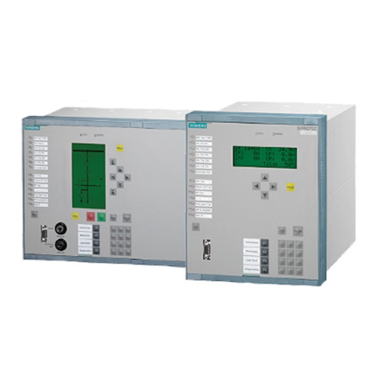
Siemens SIPROTEC 7ST6 Manuals
Manuals and User Guides for Siemens SIPROTEC 7ST6. We have
1
Siemens SIPROTEC 7ST6 manual available for free PDF download: Manual
Siemens SIPROTEC 7ST6 Manual (356 pages)
Numerical Overhead Contact Line Protection for AC Traction Power Supply
Brand:
Siemens
| Category:
Power distribution unit
| Size: 7.09 MB
Table of Contents
Functions 3
3
Table of Contents
7
1 Introduction
15
Overall Operation
16
Application Scope
19
Characteristics
21
2 Functions
25
General
26
Functional Scope
26
Configuration of the Functional Scope
26
Setting Notes
27
Settings
29
Device
30
Trip Dependent Indications
30
Spontaneous Indications on the Display
30
Setting Notes
30
Settings
31
Information List
31
Power System Data 1
33
Setting Notes
33
Settings
36
Information List
37
Change Group
38
Purpose of the Setting Groups
38
Setting Notes
38
Settings
39
Information List
39
Power System Data 2
40
Setting Notes
40
Settings
41
Information List
43
Oscillographic Fault Records
44
Functional Description
44
Setting Notes
45
Settings
46
Information List
46
Distance Protection
47
Enabling the Distance Protection
47
Distance Protection with Combined Tripping Characteristic
48
Distance Protection with Polygonal Tripping Characteristic
50
Short-Circuit Detection by Current and Voltage Angle Changes
52
Tripping Logic of the Distance Protection
54
Tripping Characteristic for Manual Reclose
57
Tripping Characteristic for Manual Close
58
Zone Changeover (Only for 16.7 Hz)
59
Setting Notes
60
Settings
69
Information List
74
Overcurrent Protection
76
Functional Description
76
Setting Notes
79
Settings
82
Information List
83
High-Speed Overcurrent Protection
84
Functional Description
84
Setting Notes
85
Settings
86
Information List
86
Emergency Overcurrent Protection
87
General
87
Functional Description
87
Setting Notes
88
Settings
89
Information List
89
Overvoltage and Undervoltage Protection
90
Overvoltage Protection
90
Undervoltage Protection
91
Setting Notes
92
Settings
93
Information List
93
Thermal Overload Protection
94
Ambient Temperature Sensing
95
Catenary Changeover
97
Setting Notes
99
Settings
101
Information List
101
Circuit Breaker Failure Protection
103
Functional Description
103
Setting Notes
106
Settings
108
Information List
108
Trip Supervision
109
Functional Description
109
Setting Notes
110
Settings
110
Information List
110
Defrosting Protection
111
Functional Description
111
Setting Notes
117
Settings
119
Information List
119
Inrush Restraint
120
Functional Description
120
Setting Notes
122
Settings
123
Information List
123
Automatic Reclosure Function
124
Functional Description
124
Setting Notes
131
Settings
139
Information List
140
Synchronism and Voltage Check
142
Functional Description
142
Setting Notes
145
Settings
150
Information List
151
Fault Locator
152
Functional Description
152
Setting Notes
154
Settings
155
Information List
155
It Function (Current-Time Integral)
156
Function Description It Procedure
156
Function Description 2P-Procedure
159
Setting Notes
163
Settings
165
Information List
165
Monitoring Function
166
Hardware Monitoring
166
Software Monitoring
167
Fuse Failure Monitor
167
Setting Notes
169
Settings
169
Information List
169
Trip Circuit Supervision
170
Functional Description
170
Setting Notes
173
Settings
173
Information List
173
Protection Function Control
174
General
174
Line Energization Recognition
174
Detection of the Circuit Breaker Position
176
Pickup Logic for the Entire Device
177
Tripping Logic of the Entire Device
178
Pickup of the Automatic Test Unit for the Overhead Contact Line (Only for 16.7 Hz)
182
Setting Notes
183
Testing
184
Functional Description
184
Setting Notes
185
Information List
185
Auxiliary Functions
186
Message Processing
186
Functional Description
186
Measurement
190
Functional Description
190
Information List
191
Statistics
192
Functional Description
192
Setting Notes
193
Information List
193
Command Processing
194
Control Authorization
194
Command Types
194
Sequence in the Command Path
195
Interlocking
196
Information List
199
Control Device
200
Information List
200
Process Data
201
Method of Operation
201
Protocol
202
Functional Description
202
Measured Value Overview
203
Information List
204
Use in Auto-Transformer Systems
205
Functional Description
205
Setting Notes
206
3 Mounting and Commissioning
207
Mounting and Connections
208
Configuration Information
208
Hardware Modifications
212
General
212
Disassembly
213
Switching Elements on Printed Circuit Boards
216
Interface Modules
228
Reassembly
231
Mounting
232
Panel Flush Mounting
232
Rack and Cubicle Mounting
233
Checking Connections
236
Checking Data Connections of Serial Interfaces
236
Checking System Connections
238
Commissioning
240
Test Mode and Transmission Block
241
Checking Time Synchronization
241
Testing System Interfaces
242
Checking the Binary Inputs and Outputs
244
Tests for Circuit Breaker Failure Protection
247
Current and Voltage Test
248
Direction Check with Load Current
249
Measuring the Operating Time of the Circuit Breaker
250
Testing User-Defined Functions
250
Trip and Close Test with the Circuit Breaker
251
Switching Test of the Configured Operating Equipment
251
Creating Oscillographic Recordings for Test
251
Final Preparation of the Device
253
4 Technical Data
255
General
256
Analog Inputs and Outputs
256
Auxiliary Voltage
257
Binary Inputs and Outputs
257
Communication Interfaces
258
Electrical Tests
262
Mechanical Stress Tests
263
Climatic Stress Tests
264
Service Conditions
265
Design
265
Distance Protection
266
Time Overcurrent Protection
268
Voltage Protection (Optional)
274
Thermal Overload Protection
275
Circuit Breaker Failure Protection (Optional)
276
Defrosting Protection (Depending on Device Version)
277
Inrush Restraint (Optional)
277
Automatic Reclosure Function (Optional)
278
Synchronism and Voltage Check (Optional and Depending on Device Version)
279
Fault Locator (Optional)
280
It Function (Optional)
280
Trip Supervision
280
Trip Circuit Supervision
280
User Defined Functions (CFC) (Optional)
281
Auxiliary Functions
284
Dimensions
286
Housing for Panel Flush Mounting or Cubicle Mounting (Size 1 / 2 )
286
Housing for Panel Flush Mounting or Cubicle Mounting (Size 1 / 1 )
287
Appendix
289
Ordering Information and Accessories
290
Ordering Information
290
Accessories
290
Terminal Assignments
293
Panel Flush Mounting or Cubicle Mounting
293
A.2 Terminal Assignments
293
Connection Examples
297
Connection of Measured Values
297
A.3 Connection Examples
297
Current Transformer Requirements
299
Overcurrent Factors
299
Operational and Nominal Overcurrent Factor
299
Calculation Example According to IEC 60044-1
299
Default Settings
300
Leds
300
A.5 Default Settings
300
Binary Input
301
A.5.2 Binary Input
301
Binary Output
302
A.5.3 Binary Output
302
Function Keys
303
A.5.4 Function Keys
303
Default Display
304
A.5.5 Default Display
304
Pre-Defined CFC Charts
306
Protocol-Dependent Functions
309
Functional Scope
310
A.7 Functional Scope
310
Settings
311
A.8 Settings
311
Information List
321
A.9 Information List
321
Group Alarms
337
A.10 Group Alarms
337
Measured Values
338
A.11 Measured Values
338
Literature
341
Glossary
343
Index
351
Advertisement
Advertisement
Related Products
Siemens SIPROTEC 7SC805
Siemens SIPROTEC 7SJ46
Siemens SIPROTEC 7SS522 V4.6
Siemens SIPROTEC 7SS523 V3.3
Siemens SIPROTEC 7SS525 V3.3
Siemens 7SG14 Duobias-M-200
Siemens SIPROTEC 7SS523 V3.2
Siemens SIPROTEC 7SS525 V3.2
Siemens SIPROTEC 7RW600
Siemens SIPROTEC 7XR81
Siemens Categories
Industrial Equipment
Controller
Control Unit
Oven
Washer
More Siemens Manuals
Login
Sign In
OR
Sign in with Facebook
Sign in with Google
Upload manual
Upload from disk
Upload from URL