Sign In
Upload
Manuals
Brands
Siemens Manuals
Control Unit
Sinamics CU240D-2 DP
Siemens Sinamics CU240D-2 DP Manuals
Manuals and User Guides for Siemens Sinamics CU240D-2 DP. We have
7
Siemens Sinamics CU240D-2 DP manuals available for free PDF download: List Manual, Operating Instructions Manual, Getting Started Manual, Getting Started
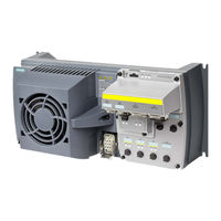
Siemens Sinamics CU240D-2 DP List Manual (910 pages)
Brand:
Siemens
| Category:
Industrial Equipment
| Size: 4.56 MB
Table of Contents
Table of Contents
3
Cu240D-2_Dp
23
Cu240D-2_Dp_F Cu240D-2_Pn
23
Cu240D-2_Pn_F
24
Cu250D-2_Dp_F
25
Cu250D-2_Pn_F
25
Advertisement
Siemens Sinamics CU240D-2 DP Operating Instructions Manual (356 pages)
Sinamics G120D Distributed Inverter Control Unit with Encoder Evaluation
Brand:
Siemens
| Category:
Inverter
| Size: 15.33 MB
Table of Contents
Changes in the Current Edition
5
Table of Contents
7
1 Fundamental Safety Instructions
13
General Safety Instructions
13
Equipment Damage Due to Electric Fields or Electrostatic Discharge
19
Warranty and Liability for Application Examples
19
Industrial Security
20
Residual Risks of Power Drive Systems
22
2 Introduction
25
About the Manual
25
Guide through the Manual
26
6 Operating Instructions, 04/2018, FW V4.9 SP10, A5E34262100B AF
28
3 Description
29
SINAMICS G120D CU240D-2 Inverter
30
Directives and Standards
31
Motors and Multi-Motor Drives that Can be Operated
34
4 Installation
35
Mechanical Installation
35
Electrical Installation
38
Overview of the Interfaces
38
Permissible Line Supplies
39
Protective Conductor
40
Grounding Converter and Motor
42
Basic EMC Rules
44
Connections and Interference Suppression
45
Equipotential Bonding
45
Branch Circuit Protection of Individual Inverters
47
Branch Circuit Protection of Multiple Inverters
50
24-V Power Supply with Multiple Inverters
52
Connections and Cables
53
Fieldbus Interfaces
61
Connecting the Motor to the Inverter in a Star or Delta Connection
61
Connecting the Motor Holding Brake
63
Factory Settings of the Inputs and Outputs
64
Default Settings of Inputs and Outputs
65
Fail-Safe Digital Input
73
Connecting the Inverter to PROFINET
74
Connecting the PROFINET Interface
76
What Do You Have to Set for Communication Via PROFINET
76
Installing GSDML
78
Connecting the Inverter to PROFIBUS
78
What Do You Have to Set for Communication Via PROFIBUS
79
Integrating the Inverter in PROFIBUS
79
Installing the GSD
80
Setting the Address
80
5 Commissioning
83
Commissioning Tools
83
Commissioning Guidelines
85
Preparing for Commissioning
86
Inverter Factory Setting
86
Selecting the Control Mode
89
Quick Commissioning with the IOP-2
90
Quick Commissioning with a PC
93
Creating a Project
94
Transfer Inverters Connected Via USB into the Project
94
Carrying out Quick Commissioning
95
Adapting the Encoder Data
97
Identify Motor Data
97
Restoring the Factory Setting
99
Resetting the Safety Functions to the Factory Setting
100
Restore the Settings to the Factory Settings (Without Safety Functions)
101
6 Advanced Commissioning
103
Overview of the Converter Functions
103
Sequence Control When Switching the Motor on and off
106
Function Description
107
Adapt the Default Setting of the Terminal Strip
108
Digital Inputs
110
Fail-Safe Digital Input
111
Digital Outputs
112
Analog Inputs
113
Drive Control Via PROFIBUS or PROFINET
115
Receive Data and Send Data
115
Telegrams
116
Control and Status Word 1
119
Control and Status Word 3
122
NAMUR Message Word
124
Parameter Channel
125
Examples for Using the Parameter Channel
129
Extending the Telegram
131
Slave-To-Slave Communication
133
Acyclically Reading and Writing Inverter Parameters
133
Jogging
134
Limit Position Control
136
Switching over the Drive Control (Command Data Set)
140
Motor Holding Brake
143
Free Function Blocks
147
Overview
147
Further Information
148
Selecting Physical Units
148
Motor Standard
148
System of Units
148
Technological Unit of the Technology Controller
150
Setting the System of Units and Technology Unit
150
Safe Torque off (STO) Safety Function
151
Function Description
152
Precondition for Using STO
154
Commissioning STO
154
Commissioning Tools
154
Safety Functions Password
154
Configuring a Safety Function
156
Interconnecting the "STO Active" Signal
157
Setting the Filter for Fail-Safe Digital Inputs
158
Setting the Forced Checking Procedure (Test Stop)
160
Acceptance - Completion of Commissioning
164
Reduced Acceptance Test after Function Expansions
165
Setpoints
165
Overview
165
Analog Input as Setpoint Source
167
Specifying the Setpoint Via the Fieldbus
169
Motorized Potentiometer as Setpoint Source
171
Fixed Speed Setpoint as Setpoint Source
174
Setpoint Calculation
177
Overview
177
Invert Setpoint
179
Inhibit Direction of Rotation
180
Skip Frequency Bands and Minimum Speed
181
Speed Limitation
183
Ramp-Function Generator
184
PID Technology Controller
188
Motor Control
192
V/F Control
193
Characteristics of U/F Control
194
Selecting the U/F Characteristic
195
Optimizing Motor Starting
197
Vector Control with Speed Controller
199
Structure of the Vector Control
199
Checking the Encoder Signal
201
Optimizing the Speed Controller
201
Advanced Settings
204
Friction Characteristic
207
Moment of Inertia Estimator
209
Pole Position Identification
215
Torque Control
216
Electrically Braking the Motor
217
DC Braking
218
Braking with Regenerative Feedback to the Line
221
Overcurrent Protection
222
Inverter Protection Using Temperature Monitoring
223
Motor Temperature Monitoring Using a Temperature Sensor
226
Motor Protection by Calculating the Temperature
230
Monitoring the Driven Load
232
Breakdown Protection
234
No-Load Monitoring
234
Blocking Protection
235
Load Monitoring
236
Torque Monitoring
237
Rotation Monitoring
238
Speed Deviation Monitoring
239
Efficiency Optimization
241
Switchover between Different Settings
245
7 Backing up Data and Series Commissioning
247
Saving Settings on a Memory Card
248
Memory Cards
248
Saving Settings to the Memory Card
249
Transferring the Settings from the Memory Card
250
Activate Message for a Memory Card that Is Not Inserted
251
Backup the Settings to a PC
252
Saving Settings and Transferring Them Using an Operator Panel
254
Other Ways to Back up Settings
255
Write Protection
255
Know-How Protection
256
Extending the Exception List for Know-How Protection
259
Activating and Deactivating Know-How Protection
260
8 Alarms, Faults and System Messages
265
Operating States Indicated on LED
265
System Runtime
269
Identification & Maintenance Data (I&M)
269
Alarms, Alarm Buffer, and Alarm History
270
Faults, Alarm Buffer and Alarm History
274
List of Alarms and Faults
278
9 Corrective Maintenance
287
Spare Parts Compatibility
287
Replacing Inverter Components
287
Spare Parts
288
Overview of Replacing Converter Components
289
Replacing a Control Unit with Enabled Safety Function
290
Replacing the Control Unit Without the Safety Functions Enabled
293
Replacing the Control Unit Without Data Backup
295
Replacing a Control Unit with Active Know-How Protection
296
Replacing a Power Module with Enabled Safety Function
299
Replacing a Power Module Without the Safety Function Being Enabled
300
Firmware Upgrade and Downgrade
301
Upgrading Firmware
303
Firmware Downgrade
305
Correcting a Failed Firmware Upgrade or Downgrade
308
Reduced Acceptance after Component Replacement and Firmware Change
309
If the Converter no Longer Responds
309
10 Technical Data
313
Performance Ratings Control Unit
313
Performance Ratings Power Module
314
SINAMICS G120D Specifications
316
Data Regarding the Power Loss in Partial Load Operation
316
Ambient Operating Conditions
317
Current Derating as a Function of the Installation Altitude
318
Pulse Frequency and Current Reduction
318
Electromagnetic Compatibility
319
Appendix
323
New and Extended Functions
323
Firmware Version 4.7 SP10
323
A.1 New and Extended Functions
323
Firmware Version 4.7 SP9
325
Firmware Version 4.7 SP6
327
Firmware Version 4.7 SP3
328
Firmware Version 4.7
331
A.1.5 Firmware Version 4.7
331
Firmware Version 4.6 SP6
332
Firmware Version 4.6
333
A.1.7 Firmware Version 4.6
333
Interconnecting Signals in the Inverter
334
Fundamentals
334
Application Example
336
A.2.2 Application Example
336
Connecting a Fail-Safe Digital Input
337
Setting a Non Standard HTL Encoder
338
Acceptance Tests for the Safety Functions
340
Recommended Acceptance Test
340
Acceptance Test STO (Basic Functions)
341
Machine Documentation
342
A.5.3 Machine Documentation
342
Documenting the Settings for the Basic Functions, Firmware V4.4
344
Manuals and Technical Support
345
Overview of the Manuals
345
Configuring Support
347
A.6.2 Configuring Support
347
Product Support
348
A.6.3 Product Support
348
Index
349
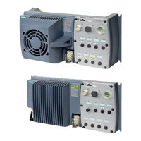
Siemens Sinamics CU240D-2 DP Operating Instructions Manual (358 pages)
Distributed converter, Control Units with encoder evaluation
Brand:
Siemens
| Category:
Media Converter
| Size: 17.08 MB
Table of Contents
Changes in this Manual
5
Table of Contents
7
Fundamental Safety Instructions
13
General Safety Instructions
13
Safety Instructions for Electromagnetic Fields (EMF)
17
Handling Electrostatic Sensitive Devices (ESD)
18
Industrial Security
18
Residual Risks of Power Drive Systems
20
Introduction
21
About the Manual
21
Guide through the Manual
22
Description
25
SINAMICS G120D CU240D-2 Inverter
25
Commissioning Tools
27
Motor Series that Are Supported
29
Installation
31
Mechanical Installation
31
Electrical Installation
34
Overview of the Interfaces
34
Permissible Line Supplies
35
Protective Conductor
36
Grounding Converter and Motor
38
Basic EMC Rules
40
Connections and Interference Suppression
41
Equipotential Bonding
41
Branch Circuit Protection of Individual Inverters
43
Branch Circuit Protection of Multiple Inverters
46
24-V Power Supply with Multiple Inverters
48
Connections and Cables
49
Star-Delta Motor Connection
57
Connecting the Motor Holding Brake
58
Factory Settings of the Inputs and Outputs
59
Default Settings of Inputs and Outputs
60
Safety Input
69
Connecting the Inverter to the Fieldbus
71
Fieldbus Versions of the Control Unit
71
Profinet
72
Connecting the PROFINET Interface
73
What Do You Need for Communication Via PROFINET
74
Integrating Inverters into PROFINET
74
Configuring Communication to the Control
74
Installing GSDML
76
Profibus
77
What Do You Need for Communication Via PROFIBUS
77
Integrating the Inverter in PROFIBUS
77
Configuring the Communication Using SIMATIC S7 Control
77
Installing the GSD
78
Setting the Address
78
Commissioning
81
Commissioning Guidelines
81
Preparing for Commissioning
82
Inverter Factory Setting
83
Selecting the Control Mode
85
Quick Commissioning with the IOP
86
Quick Commissioning with a PC
90
Creating a Project
90
Transfer Inverters Connected Via USB into the Project
91
Go Online and Start the Configuration Wizards
94
Carrying out Quick Commissioning
95
Adapting the Encoder Data
97
Identifying Motor Data
98
Restoring the Factory Setting
101
Resetting the Safety Functions to the Factory Setting
102
Restore the Settings to the Factory Settings (Without Safety Functions)
105
Advanced Commissioning
107
Overview of the Converter Functions
107
Inverter Control
109
Switching the Motor on and off
109
Adapt Inputs and Outputs
111
Digital Inputs
112
Fail-Safe Digital Input
113
Digital Outputs
114
Analog Inputs
115
Running the Motor in Jog Mode (JOG Function)
118
Control Via PROFIBUS and PROFINET with the Profidrive Profile
120
Control and Status Word 1
123
Control and Status Word 3
125
Data Structure of the Parameter Channel
127
Examples of the Parameter Channel
130
Extend Telegrams and Change Signal Interconnection
132
Slave-To-Slave Communication
134
Acyclically Reading and Writing Inverter Parameters
134
Switching over the Inverter Control (Command Data Set)
135
Setpoints
137
Overview
137
Analog Input as Setpoint Source
138
Specifying the Setpoint Via the Fieldbus
139
Motorized Potentiometer as Setpoint Source
140
Fixed Speed as Setpoint Source
142
Setpoint Calculation
145
Overview of Setpoint Processing
145
Invert Setpoint
146
Inhibit Direction of Rotation
147
Skip Frequency Bands and Minimum Speed
148
Speed Limitation
149
Ramp-Function Generator
150
Motor Control
155
V/F Control
155
Characteristics of U/F Control
156
Selecting the U/F Characteristic
157
Optimizing Motor Starting
158
Vector Control with Speed Controller
160
Checking the Encoder Signal
161
Select Motor Control
162
Optimizing the Speed Controller
163
Advanced Settings
165
Friction Characteristic
166
Moment of Inertia Estimator
168
Pole Position Identification
173
Torque Control
174
Protection Functions
176
Inverter Temperature Monitoring
176
Motor Temperature Monitoring Using a Temperature Sensor
179
Protecting the Motor by Calculating the Motor Temperature
183
Overcurrent Protection
187
Application-Specific Functions
188
Functions that Match the Application
188
Selecting Physical Units
189
Select the Motor Standard
189
Selecting the System of Units
190
Selecting the Technological Unit of the Technology Controller
191
Setting the Motor Standard, System of Units and Technology Unit Using STARTER
192
Electrically Braking the Motor
194
DC Braking
194
Braking with Regenerative Feedback to the Line
197
Motor Holding Brake
198
PID Technology Controller
203
Overview
203
Setting the Controller
204
Optimizing the Controller
207
System Protection
208
No-Load Monitoring, Blocking Protection, Stall Protection
209
Load Monitoring
211
Free Function Blocks
216
Overview
216
Further Information
216
Safe Torque off (STO) Safety Function
217
Function Description
217
Prerequisite for STO Use
219
Commissioning STO
220
Commissioning Tools
220
Safety Functions Password
220
Configuring Safety Functions
221
Interconnecting the "STO Active" Signal
222
Setting the Filter for Safety-Related Inputs
223
Setting the Forced Checking Procedure (Test Stop)
226
Activate Settings and Check Digital Inputs
228
Acceptance - Completion of Commissioning
232
Switchover between Different Settings
236
Backing up Data and Series Commissioning
239
Saving Settings on a Memory Card
240
Saving Settings to the Memory Card
241
Transferring the Settings from the Memory Card
242
Safely Remove the Memory Card
243
Backing up and Transferring Settings Using STARTER
246
Saving Settings and Transferring Them Using an Operator Panel
250
Other Ways to Back up Settings
251
Write and Know-How Protection
252
Write Protection
252
Know-How Protection
253
Settings for Know-How Protection
255
Generating an Exception List for Know-How Protection
257
Corrective Maintenance
259
Replacing Inverter Components
259
Spare Parts
259
Overview of Replacing Converter Components
260
Replacing a Control Unit with Enabled Safety Function
262
Replacing the Control Unit Without the Safety Functions Enabled
267
Replacing the Control Unit Without Data Backup
270
Replacing a Control Unit with Active Know-How Protection
271
Replacing a Power Module with Enabled Safety Function
273
Replacing a Power Module Without the Safety Function Being Enabled
274
Firmware Upgrade and Downgrade
275
Upgrading Firmware
276
Firmware Downgrade
279
Correcting a Failed Firmware Upgrade or Downgrade
282
Reduced Acceptance after Component Replacement and Firmware Change
283
If the Converter no Longer Responds
284
Alarms, Faults and System Messages
287
Alarms
287
Faults
291
Status LED Overview
296
Identification & Maintenance Data (I&M)
298
System Runtime
299
List of Alarms and Faults
300
Technical Data
309
Performance Ratings Control Unit
309
Performance Ratings Power Module
311
SINAMICS G120D Specifications
312
Data Regarding the Power Loss in Partial Load Operation
312
Ambient Operating Conditions
313
Current Derating - Depending on the Installation Altitude
314
Pulse Frequency and Current Reduction
315
Standards (PM250D)
316
Electromagnetic Compatibility
317
Appendix
321
New and Extended Functions
321
Parameter
328
The Device Trace in STARTER
331
Interconnecting Signals in the Inverter
334
Fundamentals
334
Example
336
Connecting the Safety-Related Input
338
Setting a Non Standard HTL Encoder
339
Acceptance Tests for the Safety Functions
341
Recommended Acceptance Test
341
Machine Documentation
344
Documenting the Settings for the Basic Functions, Firmware V4.4
346
Manuals and Technical Support
347
Overview of the Manuals
347
Configuring Support
349
Product Support
350
Mistakes and Improvements
350
Index
351
Advertisement
Siemens Sinamics CU240D-2 DP Operating Instructions Manual (302 pages)
Control Units, distrubuted converter
Brand:
Siemens
| Category:
Control Unit
| Size: 12.75 MB
Table of Contents
Changes in this Manual
5
Table of Contents
7
1 Fundamental Safety Instructions
13
General Safety Instructions
13
Safety Instructions for Electromagnetic Fields (EMF)
17
Handling Electrostatic Sensitive Devices (ESD)
17
Industrial Security
18
Residual Risks of Power Drive Systems
19
2 Introduction
21
About this Manual
21
Guide through this Manual
22
3 Description
23
SINAMICS G120D CU240D-2 Inverter
23
Commissioning Tools
25
Motors
27
4 Installation
29
Mechanical Installation
29
Electrical Installation
32
Permissible Line Supplies
32
Electrical Data
33
Basic EMC Rules
34
Overview of the Interfaces
36
Connections and Cables
37
8 Operating Instructions, 04/2014, FW V4.7, A5E34262100B AA
38
Connecting the Motor Holding Brake
45
Factory Settings of the Inputs and Outputs
46
Default Settings of Inputs and Outputs
47
Connecting the PROFINET Interface
49
Grounding Converter and Motor
50
Cable Protection and Cascading of the 400 V Supply
51
Cascading of the 24 V Supply
53
Connections and Interference Suppression
54
Equipotential Bonding
54
5 Commissioning
57
Commissioning Guidelines
57
Preparing for Commissioning
58
Inverter Factory Setting
59
Selecting the Control Mode
60
Defining Additional Requirements for the Application
61
Restoring the Factory Setting
62
Basic Commissioning with IOP
64
Basic Commissioning with STARTER
68
Generating a STARTER Project
68
Transfer Inverters Connected Via USB into the Project
69
Go Online and Start Wizard for Basic Commissioning
70
Carry-Out Basic Commissioning
71
Adapting the Encoder Data
72
Identifying Motor Data
73
6 Adapt Inputs and Outputs
75
Digital Inputs
76
Fail-Safe Digital Input
78
Digital Outputs
80
Analog Inputs
81
7 Configuring the Fieldbus
83
Fieldbus Versions of the Control Unit
83
Communication Via PROFINET
84
What Do You Need for Communication Via PROFINET
85
Integrating Inverters into PROFINET
85
Configuring Communication to the Control
86
Select Telegram
87
Activating Diagnostics Via the Control
87
Communication Via PROFIBUS
88
What Do You Need for Communication Via PROFIBUS
88
Integrating the Inverter in PROFIBUS
88
Configuring the Communication Using SIMATIC S7 Control
89
Setting the Address
89
Profidrive Profile for PROFIBUS and PROFINET
91
Cyclic Communication
91
Control and Status Word 1
93
Control and Status Word 3
96
Extend Telegrams and Change Signal Interconnection
98
Data Structure of the Parameter Channel
100
Slave-To-Slave Communication
105
Acyclic Communication
105
8 Setting Functions
107
Overview of the Converter Functions
107
Inverter Control
109
Switching the Motor on and off
109
Running the Motor in Jog Mode (JOG Function)
110
Switching over the Inverter Control (Command Data Set)
112
Setpoints
114
Overview
114
Analog Input as Setpoint Source
115
Specifying the Setpoint Via the Fieldbus
115
Motorized Potentiometer as Setpoint Source
116
Fixed Speed as Setpoint Source
118
Setpoint Calculation
121
Overview of Setpoint Processing
121
Invert Setpoint
122
Inhibit Direction of Rotation
122
Skip Frequency Bands and Minimum Speed
123
Speed Limitation
124
Ramp-Function Generator
125
Motor Control
130
V/F Control
130
Characteristics of U/F Control
131
Selecting the U/F Characteristic
133
Optimizing with a High Break Loose Torque and Brief Overload
134
Vector Control
135
Checking the Encoder Signal
136
Select Motor Control
136
Pole Position Identification
137
Optimizing the Speed Controller
138
Moment of Inertia Estimator
139
Advanced Settings
143
Torque Control
144
Protection and Monitoring Functions
145
Inverter Temperature Monitoring
145
Motor Temperature Monitoring Using a Temperature Sensor
148
Protecting the Motor by Calculating the Motor Temperature
151
Overcurrent Protection
153
Application-Specific Functions
154
Functions that Match the Application
154
Unit Changeover
155
Changing over the Motor Standard
156
Changing over the Unit System
156
Changing over Process Variables for the Technology Controller
157
Switching Units with STARTER
158
Electrically Braking the Motor
159
DC Braking
159
Braking with Regenerative Feedback to the Line
162
Motor Holding Brake
163
PID Technology Controller
167
Overview
167
Setting the Controller
168
Optimizing the Controller
170
Monitoring the Load Torque (System Protection)
171
Load Failure Monitoring
173
Speed Deviation Monitoring
174
Free Function Blocks
176
Overview
176
Further Information
176
Safe Torque off (STO) Safety Function
177
Function Description
177
Prerequisite for STO Use
179
Commissioning STO
179
Commissioning Tools
179
Protection of the Settings from Unauthorized Changes
180
Resetting the Safety Function Parameters to the Factory Setting
180
Changing Settings
181
Interconnecting the "STO Active" Signal
182
Setting the Filter for Safety-Related Inputs
183
Setting the Forced Checking Procedure (Test Stop)
186
Activate Settings
187
Checking the Assignment of the Digital Inputs
187
Acceptance - Completion of Commissioning
189
Switchover between Different Settings
192
9 Backing up Data and Series Commissioning
195
Saving Settings on a Memory Card
196
Saving Settings to the Memory Card
197
Transferring the Settings from the Memory Card
198
Safely Remove the Memory Card
198
Backing up and Transferring Settings Using STARTER
200
Saving Settings and Transferring Them Using an Operator Panel
202
Other Ways to Back up Settings
203
Write and Know-How Protection
204
Write Protection
204
Know-How Protection
206
Settings for the Know-How Protection
208
Creating an Exception List for the Know-How Protection
210
10 Corrective Maintenance
211
Spare Parts - External Fan
211
Overview of Replacing Converter Components
212
Replacing a Control Unit with Enabled Safety Function
214
Replacing the Control Unit Without the Safety Functions Enabled
218
Replacing the Control Unit Without Data Backup
220
Replacing a Control Unit with Active Know-How Protection
221
Replacing a Power Module with Enabled Safety Function
223
Replacing a Power Module Without the Safety Function Being Enabled
224
Upgrading Firmware
225
Firmware Downgrade
227
Correcting a Failed Firmware Upgrade or Downgrade
229
Reduced Acceptance Test after Component Replacement
230
If the Converter no Longer Responds
231
11 Alarms, Faults and System Messages
233
Alarms
233
Faults
237
Status LED Overview
241
Identification & Maintenance Data (I&M)
243
System Runtime
244
List of Alarms and Faults
245
12 Technical Data
253
Performance Ratings Control Unit
253
Performance Ratings Power Module
255
SINAMICS G120D Specifications
256
Ambient Operating Conditions
257
Derating as a Function of the Installation Altitude
258
Pulse Frequency and Current Reduction
259
Standards (PM250D)
260
Electromagnetic Compatibility
261
Appendix
265
New and Extended Functions
265
A.1 New and Extended Functions
265
Star-Delta Motor Connection and Application Examples
268
Parameter
269
A.3 Parameter
269
Handling STARTER
272
Change Settings
272
A.4 Handling STARTER
272
Optimize the Drive Using the Trace Function
273
Interconnecting Signals in the Inverter
276
Fundamentals
276
Example
278
A.5.2 Example
278
Application Examples
280
Setting an Absolute Encoder
280
A.6 Application Examples
280
Connecting the Safety-Related Input
284
Connecting Fail-Safe Digital Inputs
284
Setting a Non Standard HTL Encoder
285
Acceptance Tests for the Safety Functions
286
Recommended Acceptance Test
286
Machine Documentation
289
A.8.2 Machine Documentation
289
Log the Settings for the Basic Functions, Firmware V4.4
291
Manuals and Technical Support
292
Manuals for Your Converter
292
Configuring Support
293
Index
295
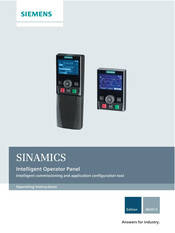
Siemens Sinamics CU240D-2 DP Operating Instructions Manual (118 pages)
Intelligent Commissioning and Application Configuration Tool
Brand:
Siemens
| Category:
Control Panel
| Size: 8.7 MB
Table of Contents
Table of Contents
5
1 Safety Notes
9
2 Overview
11
Introduction
11
Layout and Functions
12
Screen Icons
15
Menu Structure
16
3 Installation
17
Fitting the IOP
17
Initial Set-Up
18
User Definable Labels for the Status Screen
22
Firmware and Language Upgrade
23
4 Wizards
25
Example Wizard
31
Basic Commissioning with IOP
33
Wiring Diagrams
36
5 Control
45
Custom Hand Mode
49
Startup in Hand Mode
53
Hand/Auto Disable
54
6 Menu
57
Overview
57
Diagnostics
58
Parameters
62
Up/Download
68
Custom Parameter Sets
69
Extras
73
I/O Editor
85
Write Protection
87
Know-How Protection
89
7 Options
105
Door Mounting Kit
105
Hand-Held Device
107
Siemens Sinamics CU240D-2 DP Getting Started (66 pages)
Distributed Converter, Control Units with encoder evaluation
Brand:
Siemens
| Category:
Media Converter
| Size: 5.35 MB
Table of Contents
Table of Contents
5
1 Fundamental Safety Instructions
7
General Safety Instructions
7
Safety Instructions for Electromagnetic Fields (EMF)
11
Handling Electrostatic Sensitive Devices (ESD)
11
Industrial Security
12
Residual Risks of Power Drive Systems
13
2 Introduction
15
SINAMICS G120D Converter
15
Commissioning Tools
17
3 Installation
19
Fitting the CU to the PM
19
Drill Pattern SINAMICS G120D
20
Overview of the Interfaces
22
Electrical Data
23
Basic EMC Rules
24
Connections and Cables
25
Default Settings of Inputs and Outputs
39
Settings PROFIBUS DP Address with DIP Switches
41
Connecting the PROFINET Interface
42
Grounding Converter and Motor
42
Connections and Interference Suppression
44
Equipotential Bonding
44
4 Commissioning
47
Default Settings for the SINAMICS G120D
47
Commissioning with the IOP
48
Commissioning the Application
53
Reset Parameters to Factory Settings
54
5 Troubleshooting
55
List of Alarms and Faults
55
Status LED Overview
61
Further Information
63
Siemens Sinamics CU240D-2 DP Getting Started Manual (68 pages)
Power Modules
Brand:
Siemens
| Category:
Control Unit
| Size: 7.52 MB
Table of Contents
Table of Contents
5
1 Safety Notes
7
2 Introduction
11
SINAMICS G120D Inverter
11
Commissioning Tools
13
3 Installation
15
General Layout SINAMICS G120D
15
Fitting the CU to the PM
17
Drill Pattern SINAMICS G120D
19
SINAMICS G120D Electrical Data
21
EMC Installation Guidelines
23
Connections and Interference Suppression
23
Basic EMC Rules
23
Equipotential Bonding G120D-2
25
Grounding Details
27
Connections and Cable for the SINAMICS G120D
29
Settings PROFIBUS DP Address with DIP Switches
42
Connecting the PROFINET Interface
43
Selecting the Interface Assignments
44
4 Commissioning
49
Default Settings for the SINAMICS G120D
49
Commissioning with the IOP
49
Basic Commissioning with IOP and P0015 Macros
50
Commissioning the Application
55
Reset Parameters to Factory Settings
55
5 Troubleshooting
57
List of Alarms and Faults
57
Status LED Overview
62
Further Information
64
Advertisement
Related Products
Siemens CU240S DP-F
Siemens SINAMICS CU240S DP
Siemens SINAMICS CU240S PN
Siemens CU240S PN-F
Siemens CU230P-2 CAN
Siemens CU230P-2 DP
Siemens CU240E
Siemens CU230B-2
Siemens CU230E-2
Siemens CM 1542-5
Siemens Categories
Industrial Equipment
Controller
Control Unit
Oven
Washer
More Siemens Manuals
Login
Sign In
OR
Sign in with Facebook
Sign in with Google
Upload manual
Upload from disk
Upload from URL