Sign In
Upload
Manuals
Brands
Siemens Manuals
Power Tool
6SR41 series
Siemens 6SR41 series Manuals
Manuals and User Guides for Siemens 6SR41 series. We have
2
Siemens 6SR41 series manuals available for free PDF download: Operating Instructions Manual, Product User Manual
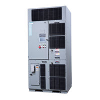
Siemens 6SR41 series Product User Manual (202 pages)
Medium-Voltage AC-Converter ROBICON Perfect Harmony GenIV
Brand:
Siemens
| Category:
DC Drives
| Size: 7.7 MB
Table of Contents
Preface
5
Version AE
5
Version AE
6
Table of Contents
7
Product User Manual Operating Instructions, Version AE 12/2009, A5E01454341C
13
Safety Precautions and Warnings
15
Overview
19
Purpose
20
Figure 2-1 Harmony Topology
21
Introduction
21
Clean Power
22
Figure 2-2 Harmonic Distortion Wave Form Comparisons (6-Pulse, 12-Pulse, and Perfect Harmony)
22
High Power Factor
22
Figure 2-3 Comparison of Perfect Harmony and a Typical Phase-Controlled SCR Drive
23
Harmony VFD Family Features
24
Perfect Harmony Features
24
VFD Output Ratings
26
VFD Scalability
26
Power Cell Bypass Option
27
Rectifier Configuration
27
Control Overview
28
Transformer Winding Configuration
28
Applications
30
Evolution
30
Intellectual Property
30
CE Marking and Directives for Perfect Harmony ™ Products
31
Figure 2-4 Power Drive System
32
Introduction
35
Theory
35
The Power Circuitry
36
Figure 3-1 Topology of Perfect Harmony VFD (3 Cells)
38
Figure 3-2 Schematic of a Typical Power Cell
39
Figure 3-3 Waveforms for Phase a
39
Figure 3-4 Waveforms for Phase B
40
Figure 3-5 Waveforms for Line-To-Line Voltage
40
Figure 3-6 Harmony Output Waveforms, 2400 Volt Drive at Full Load
41
Figure 3-7 Motor A-B Voltage and Current in Phase C at Full Load for a Harmony Drive
42
Figure 3-8 Input A-B Voltage and Current in Phase C at Full Load for a Harmony Drive
42
Figure 3-9 Block Diagram of Harmony Control Structure
45
Geniv Specifications
47
System Specifications
47
General Ambient Conditions for Storage, Transport and Operation
48
Table 4- 1 General Ambient Conditions
48
Power Cell Specifications
49
Drive Family Description
51
Product Description
51
Cabinet Outlines
54
Table 5- 1 Geniv Core Configurations
54
Cell, 4160 V Output, 200-1100 Hp
55
Figure 5-1 Geniv 4160 V Output 200-1100 Hp General Arrangement
55
Figure 5-2 Geniv 4160 V Output 200-1100 Hp Sectional View
56
Table 5- 2 Table "Nine Cell 4160 V Output Geniv, 200 - Hp
57
Cabinet Details
63
Figure 5-3 Geniv Enclosure (4160 V Output, 200-1100 Hp)
63
Input/Output Section
64
Figure 5-4 I/O Section
65
Figure 5-5 Medium Voltage Terminations (L1, L2, L3, or T1, T2, T3)
66
Transformer Section
67
Nearly Perfect Sinusoidal Output Voltages
23
Figure 5-6 Output Hall Effect Current Transducers (HEB1, HEC1)
67
Table 5- 3 Transformer Section Components
67
Table 5- 4 Transformer Section Components 4160 V, 200-260 a
67
Table 5- 5 Transformer Section Components 4160 V, 40-260 a
67
Figure 5-7 Typical Geniv 4160 V 40-140 Amp Transformer
69
Figure 5-8 Typical Geniv 4160V, 200-260 a Transformer
70
Table 5- 6 Geniv Transformer Sizing and Derating Factors1*,2
70
Figure 5-9 Cut-Out View of Fuse Assembly
71
Cell Section
72
The Control System
44
Table 5- 7 Cell Section Components 4160 V, 40-140 Amp
72
Table 5- 8 Cell Section Components 4160 V, 200 - 260 Amp
72
Table 5- 10 Cell Section Components 10000 V, 40-260 Amp
73
Table 5- 9 Cell Section Components 6600 V, 40-260 Amp
73
Figure 5-10 Geniv 40-140 a Power Cell Frame
74
Figure 5-11 Cell Installation and Latching System
75
Figure 5-17 Indicators and Labels
80
Table 5- 11 Geniv Cell Current De-Rate Factors 1*, 2
80
Control Section
82
Table 5- 12 Control Section Components
82
Table 5- 13 Analog and Digital Input/Output
85
Table 5- 21 Nine Cell Output Filter, Capacitance
99
Table 5- 22 Nine Cell Output Filter, Inductance
100
Table 5- 23 Fifteen Cell Output Filter, Capacitance
100
Table 5- 24 Fifteen Cell Output Filter, Inductance
100
Table 5- 26 Fifteen Cell Output Filter, Inductance
101
Synchronous Transfer Reactors
102
Motor Compatibility
103
IEEE 519 Conformance
104
Ride through
105
Application and Operation
107
Frame of Reference
108
Signal Frame of Reference for Motor Control
108
Signal Polarities
109
The Control Modes
110
Table 6- 2 List of Symbols Used in Figure "Block Diagram of Vectors Control Algorithmus for Induction and Synchronous Motor Control
111
Open Loop Test Mode (OLTM)
112
Open Loop Vector Control (OLVC)
112
Synchronous Motor Control (SMC)
112
Induction and Synchronous Motor Control
113
Volts/Hertz Control (V/Hz)
114
Closed Loop Control (CLVC or CSMC)
115
Slip Cpmpensation
115
Frequency Regulator
116
Flux Regulator
117
Magnetizing Current Regulator
117
Phase Lock Loop
117
Torque Current Regulator
117
High Performance Control
118
High Starting Torque
118
Low Speed Operation
118
Figure 6-4 Drive Operation in High Starting Torque Mode
119
System Program (SOP)
120
Command Generator
121
Raw Speed Reference
121
Critical Speed Avoidance
122
Polarity Control
122
Speed Profile
122
Speed Ramp
122
Speed Limit
123
Energy Saver
124
Drive Output Torque Limiting
126
Torque/Regeneration Limit
126
Input Under-Voltage Rollback
127
Field-Weakening Limit
128
Input Single-Phase Rollback
128
Transformer Thermal Rollback
128
Cell Current Overload
129
Auto Tuning
130
Drive Tuning
130
Spinning Load
131
User IO
133
Data Logs
134
Event Log
134
Fault Log
134
Historic Log
134
Faults and Alarms
135
Motor Overload
136
Input Side Monitoring and Protection
138
One Cycle Protection
139
Excessive Drive Losses
140
Figure 6-15 Inverse Time-To-Trip Curves Left - Idle State, Right - Run State
141
Cell Bypass
143
Fast Bypass
143
Fast Bypass Process
143
Figure 6-16 Typical Power Cell with Bypass Contactor
145
Neutral Point Shift During Bypass
146
Drive Host
151
Tool Suite
151
NXG Debug Utility
152
Dual Frequency Braking
153
Introduction to Dual Frequency Braking
153
Operation
153
Limitations
155
Debug Functionality
157
Application Specific Features
159
Control Mode Summary
159
Control Loops
160
Current Loop
160
Flux Loop
160
Speed Loop
160
System Program
161
Speed Droop
162
Long Cable Applications
163
Output Filters
164
Introduction
165
Synchronous Transfer
165
VFD Synchronous Transfer Implementation
165
Input/Output Signals for Sync Transfer
167
Up Transfer Implementation
167
Down Transfer Implementation
169
Parallel Control
171
Available Networks
172
Communication Interfaces
172
Multiple Networks
172
How Does Protopstm Work
173
Process Availability - the Perfect Harmony Advantage
173
What Is Protopstm
173
Protopstm Implementation
174
The Protopstm Advantage
174
Abbreviations
175
Table A- 1 Commonly Used Abbreviations
175
Appendix
181
B.1 Reader Comments Form
181
Reader Comments Form
181
B.2 Notes
183
Notes
183
Startup/Warranty Registration and Service Solutions
185
Glossary
187
Index
199
Table 5- 14 Nine Cell, Geniv, Core Hardwired I/O Assignments
85
Table 5- 15 15 Cell, Geniv, Core Hardwired I/O Assignments
86
Table 5- 16 Twenty-Four Cell, Geniv, Core Hardwired I/O Assignments (Subject to Change. Always Refer to the Project "A" and "B" for I/O Assignments)
87
Figure 5-22 Input Protection Interface for Trip Contacts
89
Upstream Device Ratings
91
Control Wire Way Section
92
Figure 5-26 Control Wire Way Section (with All Options)
93
Cooling
94
Table 5- 17 Blower Components (4160 V Drives)
94
Table 5- 18 Blower Components (6600 V Drives)
95
Table 5- 19 Blower Components (10000 V Drives)
95
Table 5- 20 Blower Speed Settings
95
Long Cable Filters
99
Reactors and Capacitors
99
Advertisement
Siemens 6SR41 series Operating Instructions Manual (224 pages)
Medium-voltage Drive SINAMICS PERFECT HARMONY
Brand:
Siemens
| Category:
Power Tool
| Size: 13.55 MB
Table of Contents
Table of Contents
5
Edition
4
Table of Contents
12
1 Introduction
17
About These Instructions
17
Text Format Features
18
Warning Symbols on the Device
19
Introduction
20
2 Safety Notes
21
General Safety Information
21
Safety Concept
22
Observing the Five Safety Rules
23
Safety Information and Warnings
24
ESD-Sensitive Components
26
Figure 2-1 ESD Protective Measures
27
Electromagnetic Fields in Electrical Power Engineering Installations
28
Information for Nominated Persons in Control of an Electrical Installation
29
Security Information
29
3 Description
31
Cabinet Details
31
Supply Scope
31
Input / Output Section
31
Cell Section
32
Control Section
32
Control Door Cabinet Components
34
Figure 3-1 Multi-Language Keypad and Display Interface
35
Figure 3-2 Operator Panel KTP700
36
Fault Reset
37
Cooling Section
39
Maintenance
41
Description of the Option Codes
42
Modbus Interface (Software Activation) (Option G22)
42
Modbus Interface (Software Activation) (Option G32)
42
Devicenet Profile 12 Interface (Option G23)
42
Devicenet Profile 12 Interface (Option G43)
42
Control Net Interface (Option G26)
42
Control Net Interface (Option G46)
42
Modbus Ethernet Interface (Software Activation) (Option G28)
42
Modbus Ethernet Interface (Software Activation) (Option G38)
43
PROFIBUS DP (Option G91)
43
PROFIBUS DP (Option G93)
43
Connection for Control Voltage Provided by Customer AC 220/230 V (Option K68)
43
Control Voltage AC 12 V Internal (Option K69)
43
Connection for Control Voltage Provided by Customer AC 120 V (Option K79)
43
Output Reactor (Option L09)
43
Bidirectional Synchronized Bypass Operation (Option L29)
44
Cabinet Illumination and Service Socket in Trigger and Control Section (Option L50)
45
Cabinet Anti-Condensation Heating, Temperature-Monitored (Option L55)
46
X 2 Thermistor Protection Relays for Alarms and Faults (Option L81)
46
X 2 Thermistor Protection Relays for Alarms and Faults (Option L82)
46
Figure 3-3 Cabinet Anti-Condensation Heating
46
Pt100 Evaluation Units with 3 Inputs each (Option L91)
47
Pt100 Evaluation Unit with 6 Inputs and 2 Analog Outputs (Option L93)
47
Pt100 Evaluation Unit with 6 Inputs for Ex-Proof Motors And6 Analog Outputs(Option L95)
47
Mechanical Safety Locking System - Castell (Option M10)
48
Gland Plates (Option M35)
48
Figure 3-4 Principle of the Mechanical Safety Locking System - Castell
48
Gland Plates (Option M36)
49
Gland Plates (Option M37)
49
IP42 Degree of Protection (Option M42)
49
Redundant Fan (Option M61)
49
Drive Prepared for Duct Flange Connection in Front (M64)
49
Harsh Environment Conditions (M67)
50
Drive Prepared for Duct Flange Connection in Rear (M68)
50
Extended Space for Bottom Cable Entry (Option M69)
51
Controlled Outgoing Circuit for Auxiliary Equipment 400 V 3 AC or 460/480 V 3 AC (Option N30)
51
Controlled Outgoing Circuit for Auxiliary Equipment 400 V 3 AC or 460/480 V 3 AC (Option N31)
52
Table 3-1 Outgoing Circuit for Auxiliary Equipment (Option N30)
52
Table 3-2 T-X30 Terminal Strip for Connecting Auxiliary Equipment
52
Table 3-3 Outgoing Circuit for Auxiliary Equipment (Option N31)
52
Controlled Outgoing Circuit for Auxiliary Equipment 400 V 3 AC or 460/480 V 3 AC (Option N32)
53
Table 3-4 T-X30 Terminal Strip for Connecting Auxiliary Equipment
53
Table 3-5 Outgoing Circuit for Auxiliary Equipment (Option N32)
53
Table 3-6 T-X30 Terminal Strip for Connecting Auxiliary Equipment
53
Controlled Outgoing Circuit for Auxiliary Equipment 400 V 3 AC or 460/480 V 3 AC (Option N33)
54
Controlled Outgoing Circuit for Auxiliary Equipment 230 V 1 AC or 120 V 1 AC (Option N35)
54
Table 3-7 Outgoing Circuit for Auxiliary Equipment (Option N33)
54
Table 3-8 T-X30 Terminal Strip for Connecting Auxiliary Equipment
54
Table 3-9 Outgoing Circuit for Auxiliary Equipment (Option N35)
54
Controlled Outgoing Circuit for Auxiliary Equipment 230 V 1 AC or 120 V 1 AC (Option N36)
55
Table 3-10 T-X30 Terminal Strip for Connecting Auxiliary Equipment
55
Table 3-11 Outgoing Circuit for Auxiliary Equipment (Option N33)
55
Table 3-12 T-X30 Terminal Strip for Connecting Auxiliary Equipment
55
Controlled Outgoing Circuit for Auxiliary Equipment 230 V 1 AC or 120 V 1 AC (Option N37)
56
Controlled Outgoing Circuit for Auxiliary Equipment 230 V 1 AC or 120 V 1 AC (Option N38)
56
Table 3-13 Outgoing Circuit for Auxiliary Equipment (Option N33)
56
Table 3-14 T-X30 Terminal Strip for Connecting Auxiliary Equipment
56
Table 3-15 Outgoing Circuit for Auxiliary Equipment (Option N33)
56
Motor-Side Grounding Switch (Option N45)
57
Power Supply for Auxiliaries 24 V DC/2.5 a (Option N75)
57
Cell Bypass (Option U11)
57
Individual Redundant Cell (Option U12)
57
Table 3-16 T-X30 Terminal Strip for Connecting Auxiliary Equipment
57
Redundant Cell Rank (Option U13)
58
Sinusodial Filter (Option Y15)
58
4 Preparing for Use
59
Requirements for Installation Location
59
Checking on Delivery
60
The Purpose of Shock and Tilt Indicators
61
Monitoring the Transport
62
Figure 4-1 Transport Indicators
62
Transportation
65
Transporting the Cabinet Units
65
Transporting the Cabinet Units
66
Transport Using a Crane
67
Figure 4-2 Back View
68
Operating Instructions Rev
68
Transport Using a Fork Lift Truck
69
Definition of a Packed and Unpacked Device
70
Transport Markings
70
Transport Requirements
70
Figure 4-3 Proper Fork Lift Handling and Dimensions
70
Take the Center of Gravity into Account
71
Figure 4-4 Example Illustration of Centers of Gravity
71
Transport with a Fork-Lift Truck
72
Transport with a Crane
72
Using Lifting Rods
73
Force Absorption
73
Figure 4-5 Sticker
74
Figure 4-6 Securing the Lifting Rods
74
Receiving and Unpacking
75
Receiving
75
Unpacking
75
Off-Loading
77
Transportation and Handling
78
Transporting the Cabinet Units
78
Transporting the Cabinet Units
79
Transport Using a Crane
80
Figure 4-7 Back View
81
Transport Using a Fork Lift Truck
82
Figure 4-8 Proper Fork Lift Handling and Dimensions
83
5 Assembly
85
Protective Earthing Bars Connection
85
Assembly Instructions
86
Requirements for the Installation Location
86
Required Tools
86
Combining Two Transport Units: Output Reactor (L09)And Sine-Wave Filter (Y15)
87
Combining Several Transport Units
88
Figure 5-1 Installing the Transport Units
88
Unlocking the Power Section Doors Manually
89
Figure 5-2 Combining Power Cell Cabinet and Transformer Cabinet (Back View)
89
Unlocking the Power Section Doors Manually
90
Figure 5-3 Orifice for Opening the Doors Manually
90
Connecting the Transport Units and Power Section Cables
91
Figure 5-4 Orifice for Opening the Doors Manually
91
Connecting the Transport Units
93
Figure 5-5 Connecting the Transport Units
93
Overview of Connection Points in the Converter
94
Figure 5-6 Connection Points in the Converter
94
Connecting the Power Section Cables (M69)
95
Figure 5-7 Lugs for Power Section Cables
95
Connecting the Power Section
96
Figure 5-8 Lugs in an Additional Cabinet (Option L09 or Y15)
96
Connecting the Power Section Cables between Transformer Cabinet and Filter Cabinet
97
Figure 5-10 Installing the Fans
100
Grounding, Cabling, and Shielding Recommendations
108
Cable Gland Plates Removal and Installation Guidelines
114
Closing the Make-Proof Grounding Switch
115
Advertisement
Related Products
Siemens SIMOTRAS 6SG7065
Siemens 6SE7021-0EP60
Siemens 6SN1123-1AA00-0JA1
Siemens 6SN1123-1AA00-0LA1
Siemens 6SE7028-8FC85-1AA0
Siemens 6SE7033-1EE85-1AA0
Siemens 6SE7037-7HH85-1AA0
Siemens 6SL3210-1KE11-8AF2
Siemens 6SL3210-1KE22-6AP1
Siemens 6SL3210-1KE23-2AF1
Siemens Categories
Industrial Equipment
Controller
Control Unit
Oven
Washer
More Siemens Manuals
Login
Sign In
OR
Sign in with Facebook
Sign in with Google
Upload manual
Upload from disk
Upload from URL